EP1564353A2 - Verriegelungsmulde - Google Patents
Verriegelungsmulde Download PDFInfo
- Publication number
- EP1564353A2 EP1564353A2 EP05405056A EP05405056A EP1564353A2 EP 1564353 A2 EP1564353 A2 EP 1564353A2 EP 05405056 A EP05405056 A EP 05405056A EP 05405056 A EP05405056 A EP 05405056A EP 1564353 A2 EP1564353 A2 EP 1564353A2
- Authority
- EP
- European Patent Office
- Prior art keywords
- trough
- locking
- opening
- anchoring
- anchoring element
- Prior art date
- Legal status (The legal status is an assumption and is not a legal conclusion. Google has not performed a legal analysis and makes no representation as to the accuracy of the status listed.)
- Withdrawn
Links
Images


Classifications
-
- E—FIXED CONSTRUCTIONS
- E05—LOCKS; KEYS; WINDOW OR DOOR FITTINGS; SAFES
- E05B—LOCKS; ACCESSORIES THEREFOR; HANDCUFFS
- E05B15/00—Other details of locks; Parts for engagement by bolts of fastening devices
- E05B15/02—Striking-plates; Keepers; Bolt staples; Escutcheons
- E05B15/0205—Striking-plates, keepers, staples
- E05B15/024—Striking-plates, keepers, staples adjustable
Definitions
- the invention relates to a locking recess according to the preamble of the claim 1.
- Locking recesses are especially for withmaschineriegelstangen or Kantriegel provided doors to the end of the rod or the bolt in a bag or to receive trough opening and thus to keep the door in its closed position.
- the trough opening is closed with the door closed by the rod or behind the latch against the opening direction of the door. Is the trough opening positioned sufficiently accurately, it can exert a pulling force on the door leaf, so that the closing effect is increased.
- a locking recess is known, which is a subsequent Positioning of the trough opening allowed.
- This locking recess is constructed in two parts, it consists of a cup-shaped locking device and a crown-shaped Floor anchoring device consists.
- the locking device or the depression element has an eccentrically arranged, round pocket for receiving the end of Floating bolt on. It is within the ground anchoring device in any Rotatable position and fixable in this position by means of a screw.
- a disadvantage of this locking recess is that the desired position is not set very precisely. To maximize flexibility in positioning to allow the bag must be made relatively large. This indicates the floating bolt bar in the bag, however, a lot of game on. She rattles and the train on the Door is insufficient. This is especially the case with flat drive bar rods of the case, as the round bag is too big. However, if the bag is made smaller, the position can the bag can only be adjusted over a small area.
- the inventive locking recess has at least two nested one another Parts, wherein an outer part of an anchoring element for fixed anchoring the trough and an inner part of a trough element with a trough opening for receiving one end of a locking bar of a door leaf. At least one of these parts, which is an outer part in relation to the depression element, is asymmetrical along a horizontally extending central axis of the well opening educated.
- the trough opening can be centric or eccentric in the trough element be arranged. This means that even the trough element itself can be eccentric be.
- the individual parts are preferably interlocked with one another in a form-fitting manner. Thereby can achieve a precise positioning and a preset position can be fix in a simple manner, without the risk that this position during the Fixation is postponed again.
- At least the anchoring element asymmetrically formed.
- An advantage of this embodiment is that two parts are sufficient to position the trough opening in any position. This is special then the case when two of the parts, for example, the anchoring element and the trough element are formed eccentrically. This will be a double eccentric educated.
- the trough opening can thus be made relatively small and narrow.
- the trough opening may have any shape. It can be round, but also oblong, e.g. be oval or rectangular, since they are always with their longitudinal axis can be positioned parallel to the door.
- Such locking recesses with elongated Muldenöfnungen are particularly suitable for use with flat bottomed fuel rods Ends suitable because the width and length of the trough opening according to the Adjust the dimensions of the flat end and make the opening optimally small can be. This adjustment ensures that the driving bolt level or the Can be kept virtually free of play in the trough.
- the opening at an angle to the vertical, so the trough opening can be slightly oblique be arranged in the trough element. This increases the pulling force on the door. This arrangement also ensures that the bar is lifted when the door is opened can. This is especially important in panic doors.
- At least three parts which are nested in each other.
- at least one compensation element is between arranged the anchoring element and the trough element.
- all nested parts are circular-cylindrical, wherein their cylinder walls have thicknesses which increase steadily along the circumference, i.e. their receiving openings are arranged eccentrically. In this case let the nested parts rotate relative to each other until the desired position is reached.
- the individual nested parts rectangular shaped, each with two opposite side walls different Have thicknesses.
- the side walls of the anchoring element have outer Surfaces on which define a common arc.
- the individual parts with each other or with respect to the anchoring element in Nutenrlochitch displaceable.
- FIG. 1 shows an inventive locking recess V is shown.
- This locking recess V is stationary in a hole or a bore B in use fixed.
- the spaces between hole B and ⁇ usserem Sheath of the trough V potted or glued.
- Such holes B mounted under the door, so that with the door closed one end of a Espagnolette bar or a Kantriegels be introduced into the locking recess can.
- the hole B can be arranged in the ground, but also in the ceiling.
- This text refers to an arrangement of the device in Ground. In the case of an arrangement in the ceiling, the directions and locations are corresponding to read inversely.
- the locking recess V has an anchoring element 1, at least one compensating element 2, 3 and a trough element 4.
- the single ones Elements are arranged one inside the other in the above order, with the Anchoring element 1 forms the outermost element.
- the individual elements can all made of metal. However, it is also possible to have individual parts or all parts made of plastic or other suitable material. It is also possible, to provide the trough element 4 with a plastic insert. This embodiment has the advantage that rattling noises are damped.
- Each element has two opposite side walls 11, 12, 21, 22, 41, 42, which have different thicknesses from each other. It is also possible that only one or more of the compensating elements, the trough element, the anchoring element or only a part of these elements is formed and the rest Elements are designed symmetrically.
- the anchoring element 1 is shown. It preferably has one round bottom 10, from which side walls 11, 12 at least approximately raise vertically.
- the side walls 11, 12 are diametrically opposed to each other arranged and define a circumferential circle K or are two circle segments S.
- the two circle segments S are preferably different sizes.
- the outer surface of the side walls 11, 12 has attachment notches or ribs 13, which allow a better fixation of the anchoring element 1 in the hole B.
- the anchoring element 1 has a U-shaped receiving opening 14, which is bounded by the side walls 11, 12 and at the other two opposite Ends is open.
- the first compensation element 2 has a substantially U-shaped cross-section and consists essentially from a bottom 20 and two mutually parallel side walls 21, 22. It is open on the other two opposite sides. Preferably, it is made of a bar profile. Its outer mass are such that they are at least approximately exactly in the receiving opening 14 of the anchoring element 1 fits. This applies to the first compensation element shown in FIG. 4a Second
- the second compensating element 3 has outer dimensions, which in the corresponding Receiving opening 25 of the first compensating element 2 fits.
- the side walls 21, 22 of the compensating element 2 each have a first outer groove 23, in which thus the first inner sliding blocks 15 are guided. Further, on the inner sides of these side walls 21, 22 each have a second inner sliding block 24, which in this example is spaced below the first slot guide are located. These second inner sliding blocks 24 are in corresponding second out outer grooves of the second compensating element 3, as shown in Figure 1 is.
- the trough element 4 which is shown in FIGS. 5a to 5c, has a cuboidal shape Main body 45 and arranged thereon, this projecting support flange 44 on.
- the support flange 44 is, as shown in Figure 1, on the surface the floor or ceiling and covers the rest, in the hole B located elements.
- the trough element 4 is closed to the anchoring element 1 through a bottom 40 and has in the main body 45 an outwardly open pocket or Trough opening 43 for receiving the end of the drive bolt bar or the channel latch on.
- the trough opening 43 is a slot, with others Shapes are possible.
- the slot extends at least approximately parallel to the above-described Nuten Installationen.
- the trough element 4 each have an outer groove, the third outer grooves 46, which in two opposite, parallel to each other side walls 41, 42 of the body 45 run. These third outer grooves 46 in turn take the third inner Sliding blocks of the second compensating element 3.
- the grooves 23, 46 and sliding blocks 15, 24 all run in the same direction and in parallel to the respective soil. Furthermore, opposite groove guides are each on same height arranged. This allows the compensation elements 2, 3 and the Remove dump element 4 in a simple manner, turn 180 ° and again put together. Only when the optimal position of the trough opening 43 relative to the anchoring element 1 is fixed, the anchoring element in the bore B shed and fixed.
- Figure 2 is shown how the mass of the individual elements 1, 2, 3, 4 to each other are coordinated. Preferably, their length is such that they on one side of the Circle circumference K. This is also before the final fixation of the anchoring element 1 ensures stabilization of its position in the hole.
- the compensation elements 2, 3 and the trough element 4 in a longitudinal direction relative to the anchoring element 1 slidably. It is but also possible that only one or a part of the elements is displaceable, these elements have different thickness sidewalls. It is also possible the trough element without the use of intermediate compensation elements to be positioned in the anchoring element.
- the trough element can also be formed with a symmetrically arranged trough opening.
- all elements have different thickness sidewalls and are all compensating elements and also the trough element variable in position, the adjustability is increased in the smallest space. This is further increased by the eccentric arrangement of the depression opening in the depression element.
- the individual insert elements 2, 3, 4 need not necessarily be designed to be open, but may, for example, be designed as pots with round or cuboidal basic body with a closed jacket.
- it is possible to fix the individual elements with a common fixing means, for example a screw.
- the individual are nested Parts formed circular cylindrical.
- the trough opening can also be any In particular, it may have a rectangular or round cross-section have.
- the trough element 4 is direct, i. without using a compensating element, in the anchoring element 1 inserted.
- the trough element 4 has in this example, in particular can be seen with reference to Figures 6e and 6g, a trough opening 43 in the form a long hole. Again, however, any other shape is possible. In particular, can the trough opening 43 may also be arranged eccentrically.
- At least the anchoring element 1 has a cylinder wall 11 ', whose thickness along its circumference steadily increasing or decreasing.
- the trough element can also be a steadily thickening Side wall 41 'have.
- the trough element 4 is in its relative position fixed to the anchoring element 1.
- a screw 5 is preferably used, which passes through a passage opening 16 into a threaded bore 47 of the trough element 4 engages.
- the head of the screw 5 is in a downwardly open, also eccentrically arranged and preferably round recess 17 of the Anchoring element 1 sunk.
- the trough element has in this case preferably a recess into which the screw head is retractable. Other types of attachment are possible.
- the outer bottom of the trough element 4 and the lower inner surface of the anchoring element 1 preferably have interlocking teeth 18, 48, which prevent unwanted rotation of the elements against each other.
- These Serrations 18, 48 are shown in broken lines in FIG. 6b or in FIGS. 6d and 6f recognizable.
- the gears 18, 48 allow a certain number of twisting positions, for example 12.
- a fixation by means of the screw 5 is not mandatory, since the teeth 18, 48 usually already sufficient Ensure against rotation.
- the anchoring element 1 is potted or glued in the hole B.
- FIGS. 7a to 7d show a further embodiment of an anchoring element 1 and an associated depression element.
- the rotation is not done via gears but by means of a laterally insertable pin 19 which fixes the tray element 4 in position.
- the trough element 4 has on its underside corresponding receiving openings 48 ', in particular milled cuts, in which the pin 19 engages.
- the depression element 4 can also be fixed in predetermined rotational positions, in this case a total of 12, in this embodiment.
- FIGS. 8a and 8b show a third exemplary embodiment of a trough according to the invention.
- at least one compensation element 2 available This is also sleeve-shaped or circular cylindrical and has a steadily increasing sidewall 21 'on.
- the compensating element 2 further has an eccentrically arranged passage opening 28, which can be enforced in each rotational position of the screw 5.
- the trough opening 43 is round and rectangular in Figure 8c.
- FIGS. 9a and 9b show a fourth exemplary embodiment.
- Muldenelement 4 a support flange 44 points Muldenelement 4 a support flange 44.
- he can of a hollow flat rail Covered 7, which extends over the entire door width and at sillless doors is used.
- This hollow rail 7 has in the region of Bodenmulde an opening 70 which is sufficiently large, around the trough opening 43 in all rotational positions release. Indicates the underlying depression element 4 a flange 44, as well as the existing recess 71 is the Hollow flat rail 7 big enough.
- This hollow rail 7 can also be with others Combine locking recesses.
- a sliding plate 6 is present, which covers the trough element 4 and in the position of use rests on the surrounding edge of the hole B.
- the sliding plate 6 welded on its underside Bolt 60, which can be inserted into corresponding holes of the trough element 4 are.
- the sliding plate 6 can then be glued to the floor. This sliding plate 6 protects the flooring adjacent to the trough so that it does not escape from any in the wrong position lowered shoot bolt can be damaged.
- FIG. 11a and 11b differs from that in Figures 10a and 10b, characterized in that the sliding plate 6 is not adhered is, but is screwed by means of screws 61 on the floor covering. Furthermore it is firmly connected to the trough element 4 by adhering to this, with him welded or bolted to it.
- the inventive device allows a large adjustment and is especially suitable for use with flat ends of locking bars.
Landscapes
- Securing Of Glass Panes Or The Like (AREA)
- Joining Of Building Structures In Genera (AREA)
Abstract
Description
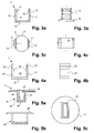
- Figur 1
- einen Querschnitt durch eine ortsfest montierte Verriegelungsmulde gemäss einer ersten Ausführungsform der Erfindung;
- Figur 2
- eine Ansicht der Verriegelungsmulde gemäss Figur 1 von oben mit schematisch dargestelltem Auflageflansch;
- Figur 3a
- ein Verankerungselement der Verriegelungsmulde gemäss Figur 1 im Querschnitt;
- Figur 3b
- eine Seitenansicht des Verankerungselements gemäss Figur 3a;
- Figur 3c
- eine Ansicht des Verankerungselements von oben;
- Figur 4a
- ein Ausgleichselement der Verriegelungsmulde gemäss Figur 1 im Querschnitt;
- Figur 4b
- eine Seitenansicht des Ausgleichselements gemäss Figur 4a;
- Figur 4c
- eine Ansicht des Ausgleichselements von oben;
- Figur 5a
- ein Muldenelement der Verriegelungsmulde gemäss Figur 1 im Querschnitt;
- Figur 5b
- eine Seitenansicht des Muldenelement gemäss Figur 5a;
- Figur 5c
- eine Ansicht des Muldenelements von oben;
- Figur 6a
- einen Querschnitt durch eine Verriegelungsmulde gemäss einer zweiten Ausführungsform der Erfindung;
- Figur 6b
- eine Ansicht der Verriegelungsmulde gemäss Figur 6a von oben;
- Figur 6c
- einen Querschnitt durch ein Verankerungselement gemäss Figur 6a;
- Figur 6d
- eine Ansicht des Verankerungselements gemäss Figur 6c von oben;
- Figur 6e
- einen Querschnitt durch ein Muldenelement gemäss Figur 6a;
- Figur 6f
- eine Ansicht des Muldenelements gemäss Figur 6e von unten;
- Figur 6g
- einen Längsschnitt durch das Muldenelement gemäss Figur 6a;
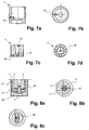
- Figur 7a
- einen Querschnitt durch eine Variante eines Verankerungselements;
- Figur 7b
- eine Ansicht des Verankerungselements gemäss Figur 7a von oben;
- Figur 7c
- einen Querschnitt durch ein in das Verankerungselement gemäss Figur 7a einsetzbares Muldenelement;
- Figur 7d
- eine Ansicht des Muldenelements gemäss Figur 7c von unten;
- Figur 8a
- einen Querschnitt durch eine Verriegelungsmulde gemäss einer dritten Ausführungsform der Erfindung;
- Figur 8b
- eine Ansicht der Verriegelungsmulde gemäss Figur 10a von oben;
- Figur 8c
- eine Ansicht der Verriegelungsmulde gemäss Figur 10b in einer weiteren Variante von oben;
- Figur 9a
- einen Querschnitt durch eine Verriegelungsmulde gemäss einer vierten Ausführungsform der Erfindung;
- Figur 9b
- eine Ansicht der Verriegelungsmulde gemäss Figur 9a von oben;
- Figur 10a
- einen Querschnitt durch eine Verriegelungsmulde gemäss einer fünften Ausführungsform der Erfindung;
- Figur 10b
- eine Ansicht der Verriegelungsmulde gemäss Figur 10a von oben;
- Figur 11a
- einen Querschnitt durch eine Verriegelungsmulde gemäss einer sechsten Ausführungsform der Erfindung und
- Figur 11b
- eine Ansicht der Verriegelungsmulde gemäss Figur 11 a von oben.
Des weiteren ist es möglich, anstelle von Nutenführungen andere Führungen zu verwenden. In diesem Fall müssen die einzelnen Einsatzelemente 2, 3, 4 auch nicht zwingend offen ausgebildet sein, sondern können, beispielsweise als Töpfe mit runden oder quaderförmigen Grundkörper mit einem geschlossenen Mantel ausgebildet sein.
Ferner ist es möglich, die einzelnen Elemente mit einem gemeinsamen Fixierungsmittel, beispielsweise einer Schraube, zu fixieren.
In den Figuren 8a und 8b ist ein drittes Ausführungsbeispiel einer erfindungsgemässen Mulde dargestellt. Hier ist nun mindestens ein Ausgleichselement 2 vorhanden. Auch dieses ist hülsenförmig bzw. kreiszylinderförmig ausgebildet und weist eine stetig dicker werdende Seitenwand 21' auf. Zur Verdrehsicherung kann sie auf ihrer inneren Unterseite und auf ihrer äusseren Unterseite mit Verzahnungen 26, 27 versehen sein. Das Ausgleichselement 2 weist ferner eine exzentrisch angeordnete Durchgangsöffnung 28 auf, welche sich in jeder Drehposition von der Schraube 5 durchsetzen lässt. In Figur 8b ist die Muldenöffnung 43 rund und in Figur 8c rechteckförmig ausgebildet.
- B
- Bohrung
- V
- Verriegelungsmulde
- K
- Umfangskreis
- S
- Kreissegment
- L
- Längslinie
- 1
- Verankerungselement
- 10
- Boden des Verankerungselements
- 11
- Erste Seitenwand des Verankerungselements
- 11'
- Seitenwand
- 12
- Zweite Seitenwand des Verankerungselements
- 13
- Befestigungsrippen
- 14
- Aufnahmeöffnung
- 15
- Erster innerer Nutstein
- 16
- Durchgangsöffnung
- 17
- Ausnehmung
- 18
- Verzahnung
- 19
- Bolzen
- 2
- Erstes Ausgleichselement
- 20
- Boden des ersten Ausgleichselements
- 21
- Erste Seitenwand des ersten Ausgleichselements
- 21'
- Seitenwand
- 22
- Zweite Seitenwand des ersten Ausgleichselements
- 23
- Erste äussere Nut
- 24
- Zweiter innerer Nutstein
- 25
- Aufnahmeöffnung
- 26
- Obere Verzahnung
- 27
- Untere Verzahnung
- 28
- Durchgangsöffnung
- 3
- Zweites Ausgleichselement
- 4
- Muldenelement
- 40
- Boden des Muldenelements
- 41
- Erste Seitenwand des Muldenelements
- 41'
- Seitenwand
- 42
- Zweite Seitenwand des Muldenelements
- 43
- Muldenöffnung
- 44
- Auflageflansch
- 45
- Grundkörper
- 46
- Dritte äussere Nut
- 47
- Gewindebohrung
- 48
- Verzahnung
- 48'
- Aufnahmeöffnung
- 5
- Schraube
- 6
- Gleitblech
- 60
- Bolzen
- 61
- Schraube
- 7
- Hohlflachschiene
- 70
- Öffnung
- 71
- Aussparung
Claims (16)
- Verriegelungsmulde (V) mit mindestens zwei ineinander angeordneten Teilen, wobei ein äusseres Teil der Verriegelungsmulde ein Verankerungselement (1) zur ortsfesten Verankerung der Mulde und ein inneres Teil ein Muldenelement (4) mit einer Muldenöffnung (43) zur Aufnahme eines Endes einer Verriegelungsstange eines Türflügels ist, wobei die Position der Muldenöffnung (43) relativ zum Verankerungselement (1) verstellbar ist,
dadurch gekennzeichnet, dass
mindestens eines der Teile, welches in Bezug auf das Muldenelement (4) ein äusseres Teil (1, 2, 3) ist, entlang einer horizontal verlaufenden Mittelachse (L) der Muldenöffnung (43) asymmetrisch ausgebildet ist. - Verriegelungsmulde gemäss Anspruch 1, wobei mindestens das Verankerungselement (1) asymmetrisch ausgebildet ist.
- Verriegelungsmulde gemäss einem der Ansprüche 1 oder 2, wobei mindestens drei ineinander angeordnete Teile vorhanden sind, wobei mindestens eines dieser Teile ein Ausgleichselement (2, 3) ist, welches zwischen Verankerungselement (1) und Muldenelement (4) angeordnet ist und wobei mindestens durch Veränderung der Positionierung des Ausgleichselements (2, 3) relativ zum Verankerungselement (1) die Lage der Muldenöffnung (43) relativ zum Verankerungselement (1) verstellbar ist.
- Verriegelungsmulde gemäss einem der Ansprüche 1 bis 3, wobei die ineinander angeordneten Teile (1, 2, 3) zylinderförmig, vorzugsweise kreiszylinderförmig, ausgebildet sind, wobei ihre Seitenwände eine Dicke aufweisen, welche entlang ihres Umfangs stetig zunimmt.
- Verriegelungsmulde gemäss einem der Ansprüche 1 bis 4, wobei die ineinander angeordneten Teile (1, 2, 3, 4) mittels Verzahnungen verdrehsicher gehalten sind.
- Verriegelungsmulde gemäss einem der Ansprüche 1 bis 5, wobei das Muldenelement (4) mittels einer Schraube (5) relativ zum Verankerungselement (1) verdrehsicher fixierbar ist.
- Verriegelungsmulde gemäss Anspruch 3, wobei das mindestens eine Ausgleichselement (2,3) und das Muldenelement (4) einen Grundkörper mit einer quaderförmigen Hülle aufweisen und wobei die diese Teile aufnehmenden Teile (1, 2, 3) eine quaderförmige Aufnahmeöffnung aufweisen.
- Verriegelungsvorrichtung nach einem der Ansprüche 3 oder 7, wobei das mindestens eine Ausgleichselement (2, 3) zwei gegenüberliegende Seitenwände (21, 22,) mit unterschiedlichen Dicken aufweist und/oder wobei das Verankerungselement (1) und/oder das Muldenelement (4) zwei gegenüberliegende Seitenwände (11, 12, 41, 42) mit unterschiedlichen Dicken aufweisen.
- Verriegelungsvorrichtung nach einem der Ansprüche 3, 7 oder 8, wobei das mindestens eine Ausgleichselement (2, 3) in einer Längsrichtung (L) relativ zum Verankerungselement (1) verschiebbar ist und/oder das Muldenelement (4) in einer Längsrichtung (L) relativ zum mindestens einen Ausgleichselement (2, 3) verschiebbar ist.
- Verriegelungselement nach den Ansprüchen 8 und 9 wobei die Elemente (1, 2, 3, 4) mittels Nutenführungen (15, 23, 24, 46) verschiebbar sind, welche in den Seitenwänden (11, 12, 21, 22, 41, 42) angeordnet sind.
- Verriegelungsvorrichtung nach einem der Ansprüche 3, 7 bis 10, wobei das mindestens eine Ausgleichselement (2, 3) einen im wesentlichen u-förmigen Querschnitt aufweist und wobei das Ausgleichselement (2, 3) an zwei gegenüberliegenden Enden offen ausgebildet ist.
- Verriegelungsvorrichtung nach einem der Ansprüche 1 bis 11, wobei das Muldenelement (4) einen quaderförmigen Grundkörper (45) aufweist, wobei die Muldenöffnung (43) im Grundkörper (45) angeordnet ist und wobei am Grundkörper (45) ein dem Grundkörper (45) vorstehender Auflageflansch (44) angeordnet ist.
- Verriegelungsvorrichtung nach einem der Ansprüche 3, 7 bis 12, wobei das Verankerungselement (1) eine u-förmige, an zwei gegenüberliegenden Seiten offene Aufnahmeöffnung (14) aufweist.
- Verriegelungsvorrichtung nach einem der Ansprüche 3, 7 bis 13, wobei das Verankerungselement (1) mindestens zwei einen Umfangskreis (K) definierende Seitenwände (11, 12) aufweist, welche paarweise diametral entgegengesetzt zueinander angeordnet sind und welche Kreissegmente (S) bilden.
- Verriegelungsvorrichtung nach einem der Ansprüche 1 bis 14, wobei die Muldenöffnung (43) ein Langloch ist.
- Hohlflachschiene (7) einer schwellenlosen Tür, dadurch gekennzeichnet, dass sie eine Öffnung (70) zur Freilassung einer Muldenöffnung (43) einer unter der Hohlflachschiene (7) anordnungsbaren Verriegelungsmulde, insbesondere einer Verriegelungsmulde gemäss einem der Ansprüche 1 bis 15, aufweist.
Applications Claiming Priority (2)
| Application Number | Priority Date | Filing Date | Title |
|---|---|---|---|
| CH1782004 | 2004-02-05 | ||
| CH1782004 | 2004-02-05 |
Publications (2)
| Publication Number | Publication Date |
|---|---|
| EP1564353A2 true EP1564353A2 (de) | 2005-08-17 |
| EP1564353A3 EP1564353A3 (de) | 2006-08-09 |
Family
ID=34683118
Family Applications (1)
| Application Number | Title | Priority Date | Filing Date |
|---|---|---|---|
| EP05405056A Withdrawn EP1564353A3 (de) | 2004-02-05 | 2005-02-04 | Verriegelungsmulde |
Country Status (1)
| Country | Link |
|---|---|
| EP (1) | EP1564353A3 (de) |
Cited By (4)
| Publication number | Priority date | Publication date | Assignee | Title |
|---|---|---|---|---|
| NL2011291A (nl) * | 2012-08-15 | 2014-02-18 | Gretsch Unitas Gmbh Baubeschl Ge | Bus voor het opnemen van een vrij einde van een kantgrendelsluiting. |
| EP3190246A1 (de) | 2016-01-11 | 2017-07-12 | Planet GDZ AG | Verriegelungsmulde |
| US10829954B2 (en) | 2016-09-19 | 2020-11-10 | Level Home, Inc. | Door lock bolt plate pivot system, and associated structures and methods |
| DE102017100447C5 (de) | 2017-01-11 | 2022-10-27 | Dorma-Glas Gmbh | Buchsenanordnung für einen Lagerbolzen eines Türflügels |
Family Cites Families (9)
| Publication number | Priority date | Publication date | Assignee | Title |
|---|---|---|---|---|
| US3385624A (en) * | 1966-04-20 | 1968-05-28 | Baclini David | Eccentric adjusting device |
| US3458227A (en) * | 1967-06-28 | 1969-07-29 | Henry Knox Bryson | Closure device |
| DE2318408A1 (de) * | 1973-04-12 | 1974-11-07 | Bilstein August Fa | Schliesstueck mit steg, insbesondere fuer mittelverschluesse an schwenk-kippfenstern |
| FR2747420B1 (fr) * | 1996-04-10 | 1998-05-15 | Ferco Int Usine Ferrures | Gache et embase et insert d'une telle gache |
| GB2368879B (en) * | 2000-10-17 | 2004-02-25 | Yale Security Prod Uk Ltd | Improvements in or relating to keeps |
| NL1017803C2 (nl) * | 2001-04-09 | 2002-10-10 | Lips Nederland B V | Sluitkomsamenstel. |
| DE20112738U1 (de) * | 2001-08-08 | 2001-11-22 | Bks Gmbh | Verriegelungsmulde |
| DE10146114B4 (de) * | 2001-09-19 | 2007-07-26 | Heinrich Strenger Gmbh | Verriegelungselement für durch einen ausfahrbaren Zapfen verriegelbare Türen oder Tore |
| DE20206952U1 (de) * | 2002-05-02 | 2003-06-05 | Drumm GmbH, 97337 Dettelbach | Wandaufnahme für den Riegel eines Türschlosses |
-
2005
- 2005-02-04 EP EP05405056A patent/EP1564353A3/de not_active Withdrawn
Cited By (6)
| Publication number | Priority date | Publication date | Assignee | Title |
|---|---|---|---|---|
| NL2011291A (nl) * | 2012-08-15 | 2014-02-18 | Gretsch Unitas Gmbh Baubeschl Ge | Bus voor het opnemen van een vrij einde van een kantgrendelsluiting. |
| EP3190246A1 (de) | 2016-01-11 | 2017-07-12 | Planet GDZ AG | Verriegelungsmulde |
| US10829954B2 (en) | 2016-09-19 | 2020-11-10 | Level Home, Inc. | Door lock bolt plate pivot system, and associated structures and methods |
| US11041325B2 (en) * | 2016-09-19 | 2021-06-22 | Level Home, Inc. | Tapered bolt receiver for a door lock |
| US11655654B2 (en) | 2016-09-19 | 2023-05-23 | Level Home, Inc. | Door lock bolt plate pivot system, and associated structures and methods |
| DE102017100447C5 (de) | 2017-01-11 | 2022-10-27 | Dorma-Glas Gmbh | Buchsenanordnung für einen Lagerbolzen eines Türflügels |
Also Published As
| Publication number | Publication date |
|---|---|
| EP1564353A3 (de) | 2006-08-09 |
Similar Documents
| Publication | Publication Date | Title |
|---|---|---|
| DE10031721C1 (de) | Vorrichtung an einer Lenksäule für Kraftfahrzeuge | |
| DE10138079A1 (de) | Platzhalter mit veränderbarer axialer Länge | |
| DE102008028756B3 (de) | Scharnier | |
| DE20017059U1 (de) | Verstellvorrichtung zur Neigungsverstellung der Frontblende einer Schublade | |
| DE2262341A1 (de) | Oberkantenhalterung fuer einen schwenkkippfluegel eines fensters, einer tuer od. dgl | |
| DE2060869A1 (de) | Bohrkopf | |
| DE69501227T2 (de) | Laufvorrichtung für einen Schiebeflügel | |
| DE2625181C2 (de) | Grund- oder Verstellplatte für ein Scharnier | |
| DE29600180U1 (de) | Justiereinrichtung für Unterflurauszugführungen | |
| EP1308590A1 (de) | Kantriegel für eine Tür | |
| EP1564353A2 (de) | Verriegelungsmulde | |
| DE102013101491B4 (de) | Höheneinstellbare Rundstangenführung | |
| DE29907856U1 (de) | Führungsvorrichtung zur Aufnahme von Gleit- und Schiebeelementen an Möbeln | |
| DE102008003557B4 (de) | Höhenverstellbares Türband mit antreibenden Zahnrädern | |
| DE10309946B4 (de) | Schloß | |
| DE4345103C2 (de) | Vorrichtung zur Befestigung von winkeligen Installationselementen | |
| EP2578759B1 (de) | Verriegelungsmechanismus für Ablauf | |
| DE102004027855C5 (de) | Schutzgitter mit griffförmiger Falle | |
| DE202008015022U1 (de) | Schlitzrinne mit Höhenverstellung | |
| EP1602794B1 (de) | Rahmenband | |
| AT501658A2 (de) | Vorrichtung zum befestigen eines fensterrahmens mittels einer justierschraube | |
| DE7535313U (de) | Schubkasten-fuehrungsschiene | |
| DE19607171C1 (de) | Schließblech | |
| DE29804519U1 (de) | Vorrichtung zur Verbindung eines Sitzes und eines Deckels mit einer Toilettenschlüssel | |
| AT413184B (de) | Vorrichtung für die neigungs-verstellung von schubladen-frontblenden |
Legal Events
| Date | Code | Title | Description |
|---|---|---|---|
| PUAI | Public reference made under article 153(3) epc to a published international application that has entered the european phase |
Free format text: ORIGINAL CODE: 0009012 |
|
| AK | Designated contracting states |
Kind code of ref document: A2 Designated state(s): AT BE BG CH CY CZ DE DK EE ES FI FR GB GR HU IE IS IT LI LT LU MC NL PL PT RO SE SI SK TR |
|
| AX | Request for extension of the european patent |
Extension state: AL BA HR LV MK YU |
|
| PUAL | Search report despatched |
Free format text: ORIGINAL CODE: 0009013 |
|
| AK | Designated contracting states |
Kind code of ref document: A3 Designated state(s): AT BE BG CH CY CZ DE DK EE ES FI FR GB GR HU IE IS IT LI LT LU MC NL PL PT RO SE SI SK TR |
|
| AX | Request for extension of the european patent |
Extension state: AL BA HR LV MK YU |
|
| 17P | Request for examination filed |
Effective date: 20060929 |
|
| AKX | Designation fees paid |
Designated state(s): AT BE BG CH CY CZ DE DK EE ES FI FR GB GR HU IE IS IT LI LT LU MC NL PL PT RO SE SI SK TR |
|
| 17Q | First examination report despatched |
Effective date: 20070323 |
|
| STAA | Information on the status of an ep patent application or granted ep patent |
Free format text: STATUS: THE APPLICATION IS DEEMED TO BE WITHDRAWN |
|
| 18D | Application deemed to be withdrawn |
Effective date: 20070803 |