EP1564353A2 - Striker - Google Patents
Striker Download PDFInfo
- Publication number
- EP1564353A2 EP1564353A2 EP05405056A EP05405056A EP1564353A2 EP 1564353 A2 EP1564353 A2 EP 1564353A2 EP 05405056 A EP05405056 A EP 05405056A EP 05405056 A EP05405056 A EP 05405056A EP 1564353 A2 EP1564353 A2 EP 1564353A2
- Authority
- EP
- European Patent Office
- Prior art keywords
- trough
- locking
- opening
- anchoring
- anchoring element
- Prior art date
- Legal status (The legal status is an assumption and is not a legal conclusion. Google has not performed a legal analysis and makes no representation as to the accuracy of the status listed.)
- Withdrawn
Links
Images


Classifications
-
- E—FIXED CONSTRUCTIONS
- E05—LOCKS; KEYS; WINDOW OR DOOR FITTINGS; SAFES
- E05B—LOCKS; ACCESSORIES THEREFOR; HANDCUFFS
- E05B15/00—Other details of locks; Parts for engagement by bolts of fastening devices
- E05B15/02—Striking-plates; Keepers; Bolt staples; Escutcheons
- E05B15/0205—Striking-plates, keepers, staples
- E05B15/024—Striking-plates, keepers, staples adjustable
Definitions
- the invention relates to a locking recess according to the preamble of the claim 1.
- Locking recesses are especially for withmaschineriegelstangen or Kantriegel provided doors to the end of the rod or the bolt in a bag or to receive trough opening and thus to keep the door in its closed position.
- the trough opening is closed with the door closed by the rod or behind the latch against the opening direction of the door. Is the trough opening positioned sufficiently accurately, it can exert a pulling force on the door leaf, so that the closing effect is increased.
- a locking recess is known, which is a subsequent Positioning of the trough opening allowed.
- This locking recess is constructed in two parts, it consists of a cup-shaped locking device and a crown-shaped Floor anchoring device consists.
- the locking device or the depression element has an eccentrically arranged, round pocket for receiving the end of Floating bolt on. It is within the ground anchoring device in any Rotatable position and fixable in this position by means of a screw.
- a disadvantage of this locking recess is that the desired position is not set very precisely. To maximize flexibility in positioning to allow the bag must be made relatively large. This indicates the floating bolt bar in the bag, however, a lot of game on. She rattles and the train on the Door is insufficient. This is especially the case with flat drive bar rods of the case, as the round bag is too big. However, if the bag is made smaller, the position can the bag can only be adjusted over a small area.
- the inventive locking recess has at least two nested one another Parts, wherein an outer part of an anchoring element for fixed anchoring the trough and an inner part of a trough element with a trough opening for receiving one end of a locking bar of a door leaf. At least one of these parts, which is an outer part in relation to the depression element, is asymmetrical along a horizontally extending central axis of the well opening educated.
- the trough opening can be centric or eccentric in the trough element be arranged. This means that even the trough element itself can be eccentric be.
- the individual parts are preferably interlocked with one another in a form-fitting manner. Thereby can achieve a precise positioning and a preset position can be fix in a simple manner, without the risk that this position during the Fixation is postponed again.
- At least the anchoring element asymmetrically formed.
- An advantage of this embodiment is that two parts are sufficient to position the trough opening in any position. This is special then the case when two of the parts, for example, the anchoring element and the trough element are formed eccentrically. This will be a double eccentric educated.
- the trough opening can thus be made relatively small and narrow.
- the trough opening may have any shape. It can be round, but also oblong, e.g. be oval or rectangular, since they are always with their longitudinal axis can be positioned parallel to the door.
- Such locking recesses with elongated Muldenöfnungen are particularly suitable for use with flat bottomed fuel rods Ends suitable because the width and length of the trough opening according to the Adjust the dimensions of the flat end and make the opening optimally small can be. This adjustment ensures that the driving bolt level or the Can be kept virtually free of play in the trough.
- the opening at an angle to the vertical, so the trough opening can be slightly oblique be arranged in the trough element. This increases the pulling force on the door. This arrangement also ensures that the bar is lifted when the door is opened can. This is especially important in panic doors.
- At least three parts which are nested in each other.
- at least one compensation element is between arranged the anchoring element and the trough element.
- all nested parts are circular-cylindrical, wherein their cylinder walls have thicknesses which increase steadily along the circumference, i.e. their receiving openings are arranged eccentrically. In this case let the nested parts rotate relative to each other until the desired position is reached.
- the individual nested parts rectangular shaped, each with two opposite side walls different Have thicknesses.
- the side walls of the anchoring element have outer Surfaces on which define a common arc.
- the individual parts with each other or with respect to the anchoring element in Nutenrlochitch displaceable.
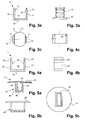
- FIG. 1 shows an inventive locking recess V is shown.
- This locking recess V is stationary in a hole or a bore B in use fixed.
- the spaces between hole B and ⁇ usserem Sheath of the trough V potted or glued.
- Such holes B mounted under the door, so that with the door closed one end of a Espagnolette bar or a Kantriegels be introduced into the locking recess can.
- the hole B can be arranged in the ground, but also in the ceiling.
- This text refers to an arrangement of the device in Ground. In the case of an arrangement in the ceiling, the directions and locations are corresponding to read inversely.
- the locking recess V has an anchoring element 1, at least one compensating element 2, 3 and a trough element 4.
- the single ones Elements are arranged one inside the other in the above order, with the Anchoring element 1 forms the outermost element.
- the individual elements can all made of metal. However, it is also possible to have individual parts or all parts made of plastic or other suitable material. It is also possible, to provide the trough element 4 with a plastic insert. This embodiment has the advantage that rattling noises are damped.
- Each element has two opposite side walls 11, 12, 21, 22, 41, 42, which have different thicknesses from each other. It is also possible that only one or more of the compensating elements, the trough element, the anchoring element or only a part of these elements is formed and the rest Elements are designed symmetrically.
- the anchoring element 1 is shown. It preferably has one round bottom 10, from which side walls 11, 12 at least approximately raise vertically.
- the side walls 11, 12 are diametrically opposed to each other arranged and define a circumferential circle K or are two circle segments S.
- the two circle segments S are preferably different sizes.
- the outer surface of the side walls 11, 12 has attachment notches or ribs 13, which allow a better fixation of the anchoring element 1 in the hole B.
- the anchoring element 1 has a U-shaped receiving opening 14, which is bounded by the side walls 11, 12 and at the other two opposite Ends is open.
- the first compensation element 2 has a substantially U-shaped cross-section and consists essentially from a bottom 20 and two mutually parallel side walls 21, 22. It is open on the other two opposite sides. Preferably, it is made of a bar profile. Its outer mass are such that they are at least approximately exactly in the receiving opening 14 of the anchoring element 1 fits. This applies to the first compensation element shown in FIG. 4a Second
- the second compensating element 3 has outer dimensions, which in the corresponding Receiving opening 25 of the first compensating element 2 fits.
- the side walls 21, 22 of the compensating element 2 each have a first outer groove 23, in which thus the first inner sliding blocks 15 are guided. Further, on the inner sides of these side walls 21, 22 each have a second inner sliding block 24, which in this example is spaced below the first slot guide are located. These second inner sliding blocks 24 are in corresponding second out outer grooves of the second compensating element 3, as shown in Figure 1 is.
- the trough element 4 which is shown in FIGS. 5a to 5c, has a cuboidal shape Main body 45 and arranged thereon, this projecting support flange 44 on.
- the support flange 44 is, as shown in Figure 1, on the surface the floor or ceiling and covers the rest, in the hole B located elements.
- the trough element 4 is closed to the anchoring element 1 through a bottom 40 and has in the main body 45 an outwardly open pocket or Trough opening 43 for receiving the end of the drive bolt bar or the channel latch on.
- the trough opening 43 is a slot, with others Shapes are possible.
- the slot extends at least approximately parallel to the above-described Nuten Installationen.
- the trough element 4 each have an outer groove, the third outer grooves 46, which in two opposite, parallel to each other side walls 41, 42 of the body 45 run. These third outer grooves 46 in turn take the third inner Sliding blocks of the second compensating element 3.
- the grooves 23, 46 and sliding blocks 15, 24 all run in the same direction and in parallel to the respective soil. Furthermore, opposite groove guides are each on same height arranged. This allows the compensation elements 2, 3 and the Remove dump element 4 in a simple manner, turn 180 ° and again put together. Only when the optimal position of the trough opening 43 relative to the anchoring element 1 is fixed, the anchoring element in the bore B shed and fixed.
- Figure 2 is shown how the mass of the individual elements 1, 2, 3, 4 to each other are coordinated. Preferably, their length is such that they on one side of the Circle circumference K. This is also before the final fixation of the anchoring element 1 ensures stabilization of its position in the hole.
- the compensation elements 2, 3 and the trough element 4 in a longitudinal direction relative to the anchoring element 1 slidably. It is but also possible that only one or a part of the elements is displaceable, these elements have different thickness sidewalls. It is also possible the trough element without the use of intermediate compensation elements to be positioned in the anchoring element.
- the trough element can also be formed with a symmetrically arranged trough opening.
- all elements have different thickness sidewalls and are all compensating elements and also the trough element variable in position, the adjustability is increased in the smallest space. This is further increased by the eccentric arrangement of the depression opening in the depression element.
- the individual insert elements 2, 3, 4 need not necessarily be designed to be open, but may, for example, be designed as pots with round or cuboidal basic body with a closed jacket.
- it is possible to fix the individual elements with a common fixing means, for example a screw.
- the individual are nested Parts formed circular cylindrical.
- the trough opening can also be any In particular, it may have a rectangular or round cross-section have.
- the trough element 4 is direct, i. without using a compensating element, in the anchoring element 1 inserted.
- the trough element 4 has in this example, in particular can be seen with reference to Figures 6e and 6g, a trough opening 43 in the form a long hole. Again, however, any other shape is possible. In particular, can the trough opening 43 may also be arranged eccentrically.
- At least the anchoring element 1 has a cylinder wall 11 ', whose thickness along its circumference steadily increasing or decreasing.
- the trough element can also be a steadily thickening Side wall 41 'have.
- the trough element 4 is in its relative position fixed to the anchoring element 1.
- a screw 5 is preferably used, which passes through a passage opening 16 into a threaded bore 47 of the trough element 4 engages.
- the head of the screw 5 is in a downwardly open, also eccentrically arranged and preferably round recess 17 of the Anchoring element 1 sunk.
- the trough element has in this case preferably a recess into which the screw head is retractable. Other types of attachment are possible.
- the outer bottom of the trough element 4 and the lower inner surface of the anchoring element 1 preferably have interlocking teeth 18, 48, which prevent unwanted rotation of the elements against each other.
- These Serrations 18, 48 are shown in broken lines in FIG. 6b or in FIGS. 6d and 6f recognizable.
- the gears 18, 48 allow a certain number of twisting positions, for example 12.
- a fixation by means of the screw 5 is not mandatory, since the teeth 18, 48 usually already sufficient Ensure against rotation.
- the anchoring element 1 is potted or glued in the hole B.
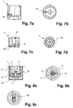
- FIGS. 7a to 7d show a further embodiment of an anchoring element 1 and an associated depression element.
- the rotation is not done via gears but by means of a laterally insertable pin 19 which fixes the tray element 4 in position.
- the trough element 4 has on its underside corresponding receiving openings 48 ', in particular milled cuts, in which the pin 19 engages.
- the depression element 4 can also be fixed in predetermined rotational positions, in this case a total of 12, in this embodiment.
- FIGS. 8a and 8b show a third exemplary embodiment of a trough according to the invention.
- at least one compensation element 2 available This is also sleeve-shaped or circular cylindrical and has a steadily increasing sidewall 21 'on.
- the compensating element 2 further has an eccentrically arranged passage opening 28, which can be enforced in each rotational position of the screw 5.
- the trough opening 43 is round and rectangular in Figure 8c.
- FIGS. 9a and 9b show a fourth exemplary embodiment.
- Muldenelement 4 a support flange 44 points Muldenelement 4 a support flange 44.
- he can of a hollow flat rail Covered 7, which extends over the entire door width and at sillless doors is used.
- This hollow rail 7 has in the region of Bodenmulde an opening 70 which is sufficiently large, around the trough opening 43 in all rotational positions release. Indicates the underlying depression element 4 a flange 44, as well as the existing recess 71 is the Hollow flat rail 7 big enough.
- This hollow rail 7 can also be with others Combine locking recesses.
- a sliding plate 6 is present, which covers the trough element 4 and in the position of use rests on the surrounding edge of the hole B.
- the sliding plate 6 welded on its underside Bolt 60, which can be inserted into corresponding holes of the trough element 4 are.
- the sliding plate 6 can then be glued to the floor. This sliding plate 6 protects the flooring adjacent to the trough so that it does not escape from any in the wrong position lowered shoot bolt can be damaged.
- FIG. 11a and 11b differs from that in Figures 10a and 10b, characterized in that the sliding plate 6 is not adhered is, but is screwed by means of screws 61 on the floor covering. Furthermore it is firmly connected to the trough element 4 by adhering to this, with him welded or bolted to it.
- the inventive device allows a large adjustment and is especially suitable for use with flat ends of locking bars.
Landscapes
- Securing Of Glass Panes Or The Like (AREA)
- Joining Of Building Structures In Genera (AREA)
Abstract
Die Verriegelungsmulde (V) weist mindestens zwei ineinander geschachtelte Teile auf,
wobei ein äusseres Teil der Verriegelungsmulde ein Verankerungselement (1) zur ortsfesten
Verankerung der Mulde und ein inneres Teil ein Muldenelement (4) mit einer
Muldenöffnung (43) zur Aufnahme eines Endes einer Verriegelungsstange eines Türflügels
ist. Die Position der Muldenöffnung (43) ist relativ zum Verankerungselement
(1) verstellbar, da mindestens eines der Teile, welches in Bezug auf das Muldenelement
ein äusseres Teil (1, 2, 3) ist, entlang einer horizontal verlaufenden Mittelachse der
Muldenöffnung (43) asymmetrisch ausgebildet ist. Diese Mulde ermöglicht einen grossen
Verstellbereich und ist insbesondere zur Verwendung mit flachen Enden von Verriegelungsstangen
geeignet.

Description
Die Erfindung betrifft eine Verriegelungsmulde gemäss Oberbegriff des Patentanspruchs
1.The invention relates to a locking recess according to the preamble of the
Verriegelungsmulden werden insbesondere für mit Treibriegelstangen oder Kantriegel versehene Türen eingesetzt, um das Ende der Stange bzw. des Riegels in einer Tasche oder Muldenöffnung aufzunehmen und so die Tür in ihrer geschlossenen Lage zu halten. Dabei wird die Muldenöffnung bei geschlossenem Türflügel von der Stange bzw. vom Riegel entgegen der Öffnungsrichtung des Türflügels hintergriffen. Ist die Muldenöffhung genügend genau positioniert, kann sie eine Zugkraft auf den Türflügel ausüben, so dass die Schliesswirkung erhöht ist.Locking recesses are especially for with Treibriegelstangen or Kantriegel provided doors to the end of the rod or the bolt in a bag or to receive trough opening and thus to keep the door in its closed position. The trough opening is closed with the door closed by the rod or behind the latch against the opening direction of the door. Is the trough opening positioned sufficiently accurately, it can exert a pulling force on the door leaf, so that the closing effect is increased.
Aus DE 201 12 738 ist eine Verriegelungsmulde bekannt, welche ein nachträgliches Positionieren der Muldenöffnung erlaubt. Diese Verriegelungsmulde ist zweiteilig aufgebaut, wobei sie aus einer topfförmigen Zuhaltevorrichtung und einer kronenförmigen Bodenverankerungsvorrichtung besteht. Die Zuhaltevorrichtung bzw. das Muldenelement weist eine exzentrisch angeordnete, runde Tasche zur Aufnahme des Endes der Treibriegelstange auf. Sie ist innerhalb der Bodenverankerungsvorrichtung in eine beliebige Position drehbar und in dieser Lage mittels einer Schraube fixierbar.From DE 201 12 738 a locking recess is known, which is a subsequent Positioning of the trough opening allowed. This locking recess is constructed in two parts, it consists of a cup-shaped locking device and a crown-shaped Floor anchoring device consists. The locking device or the depression element has an eccentrically arranged, round pocket for receiving the end of Floating bolt on. It is within the ground anchoring device in any Rotatable position and fixable in this position by means of a screw.
Nachteilig an dieser Verriegelungsmulde ist, dass sich die gewünschte Position nicht sehr genau einstellen lässt. Um eine möglichst grosse Flexibilität in der Positionierung zu erlauben, muss die Tasche relativ gross ausgebildet sein. Dadurch weist die Treibriegelstange in der Tasche jedoch relativ viel Spiel auf. Sie klappert und der Zug auf die Türe ist ungenügend. Dies ist vor allem bei flachen Treibriegelstangen der Fall, da die runde Tasche zu gross ist. Wird die Tasche jedoch kleiner ausgebildet, kann die Position der Tasche nur über einen kleinen Bereich eingestellt werden.A disadvantage of this locking recess is that the desired position is not set very precisely. To maximize flexibility in positioning to allow the bag must be made relatively large. This indicates the floating bolt bar in the bag, however, a lot of game on. She rattles and the train on the Door is insufficient. This is especially the case with flat drive bar rods of the case, as the round bag is too big. However, if the bag is made smaller, the position can the bag can only be adjusted over a small area.
Es ist deshalb Aufgabe der Erfindung, eine Verriegelungsmulde der eingangs genannten Art zu schaffen, welche einen relativ grossen Einstellbereich ermöglicht und trotzdem dem Ende der Treibriegelstange wenig Spiel lässt.It is therefore an object of the invention to provide a locking recess of the aforementioned To create kind, which allows a relatively large adjustment range and still the end of the shoot bolt bar little play leaves.
Diese Aufgabe löst eine Verriegelungsmulde mit den Merkmalen des Patentanspruchs
1.This object is achieved by a locking recess with the features of the
Die erfindungsgemässe Verriegelungsmulde weist mindestens zwei ineinander schachtelbare Teile auf, wobei ein äusseres Teil ein Verankerungselement zur ortsfesten Verankerung der Mulde und ein inneres Teil ein Muldenelement mit einer Muldenöffnung zur Aufnahme eines Endes einer Verriegelungsstange eines Türflügels ist. Mindestens eines dieser Teile, welches in Bezug auf das Muldenelement ein äusseres Teil darstellt, ist entlang einer horizontal verlaufenden Mittelachse der Muldenöffnung asymmetrisch ausgebildet. Die Muldenöffnung kann dabei zentrisch oder exzentrisch im Muldenelement angeordnet sein. Das heisst, auch das Muldenelement selber kann exzentrisch ausgebildet sein.The inventive locking recess has at least two nested one another Parts, wherein an outer part of an anchoring element for fixed anchoring the trough and an inner part of a trough element with a trough opening for receiving one end of a locking bar of a door leaf. At least one of these parts, which is an outer part in relation to the depression element, is asymmetrical along a horizontally extending central axis of the well opening educated. The trough opening can be centric or eccentric in the trough element be arranged. This means that even the trough element itself can be eccentric be.
Die einzelnen Teile sind vorzugsweise formschlüssig ineinander verschachtelt. Dadurch lässt sich eine genaue Positionierung erzielen und eine voreingestellte Position lässt sich auf einfache Weise fixieren, ohne dass Gefahr besteht, dass diese Position während der Fixierung wieder verschoben wird. The individual parts are preferably interlocked with one another in a form-fitting manner. Thereby can achieve a precise positioning and a preset position can be fix in a simple manner, without the risk that this position during the Fixation is postponed again.
In einer ersten bevorzugten Ausführungsform ist mindestens das Verankerungselement asymmetrisch ausgebildet. Vorteilhaft an dieser Ausführungsform ist, dass zwei Teile genügen, um die Muldenöffnung in einer beliebigen Lage zu positionieren. Dies ist insbesondere dann der Fall, wenn zwei der Teile, beispielsweise das Verankerungselement und das Muldenelement exzentrisch ausgebildet sind. Dadurch wird ein Doppel-Exzenter gebildet. Die Muldenöffnung lässt sich somit relativ klein und schmal ausbilden.In a first preferred embodiment, at least the anchoring element asymmetrically formed. An advantage of this embodiment is that two parts are sufficient to position the trough opening in any position. This is special then the case when two of the parts, for example, the anchoring element and the trough element are formed eccentrically. This will be a double eccentric educated. The trough opening can thus be made relatively small and narrow.
Da mindestens ein das Muldenelement umgebendes Teil asymmetrisch ausgebildet ist, kann die Muldenöffnung eine beliebige Form aufweisen. Sie kann rund, aber auch länglich, z.B. oval oder rechteckig ausgebildet sein, da sie sich stets mit ihrer Längsachse parallel zur Tür positionieren lässt. Derartige Verriegelungsmulden mit länglichen Muldenöfnungen sind insbesondere zur Verwendung mit Treibriegelstangen mit flachen Enden geeignet, da sich die Breite und Länge der Muldenöffnung entsprechend den Abmessungen des flachen Endes anpassen und die Öffnung optimal klein ausgestaltet werden kann. Diese Anpassung gewährleistet, dass sich die Treibriegelstande bzw. der Kantriegel praktisch spielfrei in der Mulde halten lässt. Des weiteren kann die Öffnung in einem Winkel zur Vertikalen verlaufen, die Muldenöffnung kann also leicht schräg im Muldenelement angeordnet sein. Dies erhöht die Zugkraft auf die Tür. Diese Anordnung gewährleistet zudem, dass beim Öffnen der Tür die Stange angehoben werden kann. Dies ist vor allem bei Paniktüren wichtig.Since at least one part surrounding the trough element is asymmetrical, the trough opening may have any shape. It can be round, but also oblong, e.g. be oval or rectangular, since they are always with their longitudinal axis can be positioned parallel to the door. Such locking recesses with elongated Muldenöfnungen are particularly suitable for use with flat bottomed fuel rods Ends suitable because the width and length of the trough opening according to the Adjust the dimensions of the flat end and make the opening optimally small can be. This adjustment ensures that the driving bolt level or the Can be kept virtually free of play in the trough. Furthermore, the opening at an angle to the vertical, so the trough opening can be slightly oblique be arranged in the trough element. This increases the pulling force on the door. This arrangement also ensures that the bar is lifted when the door is opened can. This is especially important in panic doors.
In einer zweiten bevorzugten Ausführungsform sind mindestens drei Teile vorhanden, welche ineinander geschachtelt sind. Hierfür ist mindestens ein Ausgleichselement zwischen dem Verankerungselement und dem Muldenelement angeordnet. Vorzugsweise sind dabei mindestens alle das Muldenelement umgebenden, ineinander geschachtelten Teile asymmetrisch zur Mittelachse ausgebildet, so dass ein sehr fein abgestufter Einstellbereich zur Positionierung der Muldenöffnung ermöglicht ist.In a second preferred embodiment there are at least three parts which are nested in each other. For this purpose, at least one compensation element is between arranged the anchoring element and the trough element. Preferably are at least all the Muldenelement surrounding, nested Parts designed asymmetrically to the central axis, so that a very finely graduated adjustment is made possible for positioning the trough opening.
Vorzugsweise sind alle ineinander geschachtelten Teile kreiszylinderförmig ausgebildet, wobei ihre Zylinderwände Dicken aufweisen, welche entlang des Umfangs stetig anwachsen, d.h. ihre Aufnahmeöffnungen sind exzentrisch angeordnet. In diesem Fall lassen sich die ineinander geschachtelten Teile relativ zueinander verdrehen, bis die gewünschte Position erreicht ist.Preferably, all nested parts are circular-cylindrical, wherein their cylinder walls have thicknesses which increase steadily along the circumference, i.e. their receiving openings are arranged eccentrically. In this case let the nested parts rotate relative to each other until the desired position is reached.
In einer anderen Ausführungsform sind die einzelnen ineinander verschachtelten Teile rechteckförmig gestaltet, wobei jeweils zwei gegenüberliegende Seitenwände unterschiedliche Dicken aufweisen. Die Seitenwände des Verankerungselements weisen äussere Oberflächen auf, welche einen gemeinsamen Kreisbogen definieren. Vorzugsweise sind die einzelnen Teile untereinander bzw. bezüglich des Verankerungselements in Nutenrührungen verschiebbar.In another embodiment, the individual nested parts rectangular shaped, each with two opposite side walls different Have thicknesses. The side walls of the anchoring element have outer Surfaces on which define a common arc. Preferably are the individual parts with each other or with respect to the anchoring element in Nutenrührungen displaceable.
Weitere vorteilhafte Ausführungsformen gehen aus den abhängigen Patentansprüchen hervor.Further advantageous embodiments will become apparent from the dependent claims out.
Im folgenden wird der Erfindungsgegenstand anhand von bevorzugten Ausführungsbeispielen, welche in den beiliegenden Zeichnungen dargestellt sind, erläutert. Es zeigen:
Figur 1- einen Querschnitt durch eine ortsfest montierte Verriegelungsmulde gemäss einer ersten Ausführungsform der Erfindung;
Figur 2- eine Ansicht der Verriegelungsmulde gemäss
Figur 1 von oben mit schematisch dargestelltem Auflageflansch; - Figur 3a
- ein Verankerungselement der Verriegelungsmulde gemäss
Figur 1 im Querschnitt; - Figur 3b
- eine Seitenansicht des Verankerungselements gemäss Figur 3a;
- Figur 3c
- eine Ansicht des Verankerungselements von oben;
- Figur 4a
- ein Ausgleichselement der Verriegelungsmulde gemäss
Figur 1 im Querschnitt; - Figur 4b
- eine Seitenansicht des Ausgleichselements gemäss Figur 4a;
- Figur 4c
- eine Ansicht des Ausgleichselements von oben;
- Figur 5a
- ein Muldenelement der Verriegelungsmulde gemäss Figur 1 im Querschnitt;
- Figur 5b
- eine Seitenansicht des Muldenelement gemäss Figur 5a;
- Figur 5c
- eine Ansicht des Muldenelements von oben;
- Figur 6a
- einen Querschnitt durch eine Verriegelungsmulde gemäss einer zweiten Ausführungsform der Erfindung;
- Figur 6b
- eine Ansicht der Verriegelungsmulde gemäss Figur 6a von oben;
- Figur 6c
- einen Querschnitt durch ein Verankerungselement gemäss Figur 6a;
- Figur 6d
- eine Ansicht des Verankerungselements gemäss Figur 6c von oben;
- Figur 6e
- einen Querschnitt durch ein Muldenelement gemäss Figur 6a;
- Figur 6f
- eine Ansicht des Muldenelements gemäss Figur 6e von unten;
- Figur 6g
- einen Längsschnitt durch das Muldenelement gemäss Figur 6a;
- Figur 7a
- einen Querschnitt durch eine Variante eines Verankerungselements;
- Figur 7b
- eine Ansicht des Verankerungselements gemäss Figur 7a von oben;
- Figur 7c
- einen Querschnitt durch ein in das Verankerungselement gemäss Figur 7a einsetzbares Muldenelement;
- Figur 7d
- eine Ansicht des Muldenelements gemäss Figur 7c von unten;
- Figur 8a
- einen Querschnitt durch eine Verriegelungsmulde gemäss einer dritten Ausführungsform der Erfindung;
- Figur 8b
- eine Ansicht der Verriegelungsmulde gemäss Figur 10a von oben;
- Figur 8c
- eine Ansicht der Verriegelungsmulde gemäss Figur 10b in einer weiteren Variante von oben;
- Figur 9a
- einen Querschnitt durch eine Verriegelungsmulde gemäss einer vierten Ausführungsform der Erfindung;
- Figur 9b
- eine Ansicht der Verriegelungsmulde gemäss Figur 9a von oben;
- Figur 10a
- einen Querschnitt durch eine Verriegelungsmulde gemäss einer fünften Ausführungsform der Erfindung;
- Figur 10b
- eine Ansicht der Verriegelungsmulde gemäss Figur 10a von oben;
- Figur 11a
- einen Querschnitt durch eine Verriegelungsmulde gemäss einer sechsten Ausführungsform der Erfindung und
- Figur 11b
- eine Ansicht der Verriegelungsmulde gemäss Figur 11 a von oben.
- FIG. 1
- a cross section through a fixedly mounted locking recess according to a first embodiment of the invention;
- FIG. 2
- a view of the locking recess according to Figure 1 from above with schematically illustrated support flange;
- FIG. 3a
- an anchoring element of the locking recess according to Figure 1 in cross section;
- FIG. 3b
- a side view of the anchoring element according to Figure 3a;
- Figure 3c
- a view of the anchoring element from above;
- FIG. 4a
- a compensating element of the locking recess according to Figure 1 in cross section;
- FIG. 4b
- a side view of the compensating element according to Figure 4a;
- Figure 4c
- a view of the compensation element from above;
- FIG. 5a
- a trough element of the locking recess according to Figure 1 in cross section;
- FIG. 5b
- a side view of the well element according to Figure 5a;
- FIG. 5c
- a view of the trough element from above;
- FIG. 6a
- a cross section through a locking recess according to a second embodiment of the invention;
- FIG. 6b
- a view of the locking recess according to Figure 6a from above;
- FIG. 6c
- a cross section through an anchoring element according to Figure 6a;
- FIG. 6d
- a view of the anchoring element according to Figure 6c from above;
- FIG. 6e
- a cross section through a depression element according to Figure 6a;
- FIG. 6f
- a view of the trough element according to Figure 6e from below;
- FIG. 6g
- a longitudinal section through the trough element according to Figure 6a;
- Figure 7a
- a cross section through a variant of an anchoring element;
- FIG. 7b
- a view of the anchoring element according to Figure 7a from above;
- FIG. 7c
- a cross-section through an insertable into the anchoring element according to Figure 7a depression element;
- FIG. 7d
- a view of the trough element according to Figure 7c from below;
- FIG. 8a
- a cross section through a locking recess according to a third embodiment of the invention;
- FIG. 8b
- a view of the locking recess according to Figure 10a from above;
- FIG. 8c
- a view of the locking recess according to Figure 10b in a further variant from above;
- FIG. 9a
- a cross section through a locking recess according to a fourth embodiment of the invention;
- FIG. 9b
- a view of the locking recess according to Figure 9a from above;
- FIG. 10a
- a cross section through a locking recess according to a fifth embodiment of the invention;
- FIG. 10b
- a view of the locking recess according to Figure 10a from above;
- FIG. 11a
- a cross section through a locking recess according to a sixth embodiment of the invention and
- FIG. 11b
- a view of the locking recess according to Figure 11 a from above.
In Figur 1 ist eine erfindungsgemässe Verriegelungsmulde V dargestellt. Diese Verriegelungsmulde V ist im Gebrauchszustand ortsfest in einem Loch oder einer Bohrung B fixiert. Vorzugsweise werden die Zwischenräume zwischen Bohrung B und äusserem Mantel der Mulde V vergossen oder verklebt. Üblicherweise werden derartige Bohrungen B unter der Türe angebracht, so dass bei geschlossenem Türflügel ein Ende einer Treibriegelstange oder eines Kantriegels in die Verriegelungsmulde eingeführt werden kann. Die Bohrung B kann im Boden, aber auch in der Decke angeordnet sein. Die in diesem Text bezogenen Angaben beziehen sich auf eine Anordnung der Vorrichtung im Boden. Bei einer Anordnung in der Decke sind die Richtungs- und Ortsangaben entsprechend invers zu lesen.1 shows an inventive locking recess V is shown. This locking recess V is stationary in a hole or a bore B in use fixed. Preferably, the spaces between hole B and Äusserem Sheath of the trough V potted or glued. Usually, such holes B mounted under the door, so that with the door closed one end of a Espagnolette bar or a Kantriegels be introduced into the locking recess can. The hole B can be arranged in the ground, but also in the ceiling. In the This text refers to an arrangement of the device in Ground. In the case of an arrangement in the ceiling, the directions and locations are corresponding to read inversely.
Die Verriegelungsmulde V weist ein Verankerungselement 1, mindestens ein Ausgleichselement
2, 3 und ein Muldenelement 4 auf. Hier sind zwei Ausgleichselemente
vorhanden. Ihre Anzahl kann jedoch auch kleiner oder grösser als zwei sein. Die einzelnen
Elemente sind in der oben genannten Reihenfolge ineinander angeordnet, wobei das
Verankerungselement 1 das äusserste Element bildet. Die einzelnen Elemente können
alle aus Metall gefertigt sein. Es ist jedoch auch möglich, einzelne Teile oder alle Teile
aus Kunststoff oder einem anderen geeigneten Material zu fertigen. Es ist auch möglich,
das Muldenelement 4 mit einem Kunststoffeinsatz zu versehen. Diese Ausführungsform
weist den Vorteil auf, dass Klappergeräusche gedämpft werden. The locking recess V has an
Jedes Element weist zwei gegenüberliegende Seitenwände 11, 12, 21, 22, 41, 42 auf,
welche voneinander unterschiedliche Dicken besitzen. Es ist auch möglich, dass lediglich
ein oder mehrere der Ausgleichselemente, das Muldenelement, das Verankerungselement
oder lediglich ein Teil dieser Elemente dergestalt ausgebildet ist und die übrigen
Elemente symmetrisch gestaltet sind.Each element has two
In den Figuren 3a bis 3c ist das Verankerungselement 1 dargestellt. Es weist einen vorzugsweise
runden Boden 10 auf, von welchem sich Seitenwände 11, 12 mindestens annähernd
senkrecht erheben. Die Seitenwände 11, 12 sind diametral entgegengesetzt zueinander
angeordnet und definieren einen Umfangskreis K bzw. sind zwei Kreissegmente
S. Die zwei Kreissegmente S sind vorzugsweise verschieden gross.In the figures 3a to 3c, the anchoring
Die äussere Oberfläche der Seitenwände 11, 12 weist Befestigungskerben oder -rippen
13 auf, welche eine bessere Fixierung des Verankerungselements 1 im Loch B ermöglichen.The outer surface of the
Das Verankerungselement 1 weist eine u-förmige Aufnahmeöffnung 14 auf, welche
durch die Seitenwände 11, 12 begrenzt ist und an den anderen zwei gegenüberliegenden
Enden offen ist.The anchoring
Auf der inneren Oberfläche der Seitenwände 11, 12 ist je ein erster innerer Nutstein 15
vorhanden. Im hier dargestellten Beispiel ist er im oberen Bereich angeordnet. In den
Figuren 4a bis 4c ist ein erstes Ausgleichselement 2 dargestellt. Das erste Ausgleichselement
2 weist einen im wesentlichen u-förmigen Querschnitt auf und besteht im wesentlichen
aus einem Boden 20 und zwei parallel zueinander verlaufenden Seitenwänden
21, 22. Es ist an den zwei anderen einander gegenüberliegenden Seiten offen ausgebildet.
Vorzugsweise ist es aus einem Stangenprofil gefertigt. Seine äusseren Masse
sind derart, dass es mindestens annähernd genau in die Aufnahmeöffnung 14 des Verankerungselements
1 passt. Dies gilt für das in Figur 4a dargestellte erste Ausgleichselement
2. On the inner surface of the
Weitere Ausgleichselemente, insbesondere das dritte 3, sind bis auf die Abmessungen
und die Lage der nachfolgend beschriebenen Nuten und Nutsteine gleich ausgebildet.
Das zweite Ausgleichselement 3 weist äussere Abmessungen auf, welche in die entsprechende
Aufnahmeöffnung 25 des ersten Ausgleichselements 2 passt. Für weitere Ausgleichselemente
wird die Lehre analog fortgesetzt.Further compensation elements, in particular the third 3, are down to the dimensions
and the position of the grooves and sliding blocks described below are the same.
The second compensating
Entsprechend der Lage des ersten inneren Nutsteins 15 ist an beiden äusseren Oberflächen
der Seitenwände 21, 22 des Ausgleichselements 2 je eine erste äussere Nut 23 vorhanden,
in welchen somit die ersten inneren Nutsteine 15 verschiebbar geführt sind.
Ferner ist an den Innenseiten dieser Seitenwände 21, 22 je ein zweiter innerer Nutstein
24 angeordnet, welche sich in diesem Beispiel beabstandet unterhalb der ersten Nutenführung
befinden. Diese zweiten inneren Nutsteine 24 sind in entsprechenden zweiten
äusseren Nuten des zweiten Ausgleichselements 3 geführt, wie dies in Figur 1 dargestellt
ist.According to the position of the first
Das Muldenelement 4, welches in den Figuren 5a bis 5c dargestellt ist, weist einen quaderförmigen
Grundkörper 45 und einen daran angeordneten, diesem vorstehenden Auflageflansch
44 auf. Der Auflageflansch 44 liegt, wie in Figur 1 dargestellt, auf der Oberfläche
des Bodens bzw. der Decke auf und überdeckt die restlichen, sich in der Bohrung
B befindlichen Elemente.The
Das Muldenelement 4 ist zum Verankerungselement 1 hin durch einen Boden 40 abgeschlossen
und weist im Grundkörper 45 eine nach aussen hin geöffnete Tasche oder
Muldenöffnung 43 zur Aufnahme des Endes der Treibriegelstange oder des Kantriegels
auf. Im hier dargestellten Beispiel ist die Muldenöffnung 43 ein Langloch, wobei andere
Formen möglich sind. Das Langloch erstreckt sich mindestens annähernd parallel zu
den oben beschriebenen Nutenführungen. Im montierten Zustand der Verriegelungsmulde
V entspricht diese Richtung einer Parallelen zum Türblatt. Auch das Muldenelement
4 weist je eine äussere Nut, die dritte äusseren Nuten 46 auf, welche in zwei gegenüberliegenden,
parallel zueinander verlaufenden Seitenwänden 41, 42 des Grundkörpers
45 verlaufen. Diese dritten äusseren Nut 46 nehmen wiederum die dritten inneren
Nutsteine des zweiten Ausgleichselements 3 auf. The
Die Nuten 23, 46 und Nutsteine 15, 24 verlaufen alle in derselben Richtung und parallel
zum jeweiligen Boden. Ferner sind gegenüberliegende Nutenführungen jeweils auf
gleicher Höhe angeordnet. Dadurch lassen sich die Ausgleichselemente 2, 3 und das
Muldenelement 4 auf einfache Art und Weise entfernen, um 180° drehen und wieder
zusammensetzen. Erst wenn die optimale Lage der Muldenöffnung 43 relativ zum Verankerungselement
1 festgelegt ist, wird das Verankerungselement in der Bohrung B
vergossen und fixiert.The
In Figur 2 ist dargestellt, wie die Masse der einzelnen Elemente 1, 2, 3, 4 aufeinander
abgestimmt sind. Vorzugsweise ist ihre Länge so bemessen, dass sie auf einer Seite den
Umfangskreis K berühren. Dadurch ist auch vor der endgültigen Fixierung des Verankerungselements
1 eine Stabilisierung seiner Lage in der Bohrung gewährleistet.In Figure 2 is shown how the mass of the
In der hier dargestellten Lösung sind die Ausgleichselemente 2, 3 und das Muldenelement
4 in einer Längsrichtung relativ zum Verankerungselement 1 verschiebbar. Es ist
jedoch auch möglich, dass lediglich eines oder ein Teil der Elemente verschiebbar ist,
wobei diese Elemente unterschiedlich dicke Seitenwände aufweisen. Ferner ist es möglich,
das Muldenelement ohne Verwendung von dazwischen liegende Ausgleichselementen
im Verankerungselement zu positionieren.In the solution shown here, the
Ebenso ist es möglich, das Muldenelement topfförmig auszubilden und mindestens das
letzte Ausgleichselement mit einer Aufnahmeöffnung zu versehen, welche eine Drehung
des Muldenelements erlaubt. Das Muldenelement kann auch mit einer symmetrisch
angeordneten Muldenöffnung ausgebildet sein. Weisen jedoch alle Elemente verschieden
dicke Seitenwände auf und sind alle Ausgleichselemente und auch das Muldenelement
in seiner Position variierbar, so wird die Verstellbarkeit auf kleinstem Raum
erhöht. Dies wird durch die exzentrische Anordnung der Muldenöffnung im Muldenelement
noch erhöht.
Des weiteren ist es möglich, anstelle von Nutenführungen andere Führungen zu verwenden.
In diesem Fall müssen die einzelnen Einsatzelemente 2, 3, 4 auch nicht zwingend
offen ausgebildet sein, sondern können, beispielsweise als Töpfe mit runden oder
quaderförmigen Grundkörper mit einem geschlossenen Mantel ausgebildet sein.
Ferner ist es möglich, die einzelnen Elemente mit einem gemeinsamen Fixierungsmittel,
beispielsweise einer Schraube, zu fixieren.It is also possible to form the trough element cup-shaped and to provide at least the last compensating element with a receiving opening, which allows rotation of the trough element. The trough element can also be formed with a symmetrically arranged trough opening. However, all elements have different thickness sidewalls and are all compensating elements and also the trough element variable in position, the adjustability is increased in the smallest space. This is further increased by the eccentric arrangement of the depression opening in the depression element.
Furthermore, it is possible to use other guides instead of Nutenführungen. In this case, the
Furthermore, it is possible to fix the individual elements with a common fixing means, for example a screw.
In den nachfolgend beschriebenen Figuren sind weitere bevorzugte Ausführungsformen dargestellt. In diesen Ausführungsformen sind die einzelnen ineinander verschachtelten Teile kreiszylinderförmig ausgebildet. Die Muldenöffnung kann auch hier jede beliebige Form aufweisen, insbesondere kann sie einen rechteckförmigen oder runden Querschnitt besitzen. Diese Ausführungsformen weisen den Vorteil auf, dass sie einfacher und kostengünstiger herstellbar sind als das in den Figuren 1 bis 5 dargestellte Beispiel. Ein weiterer Vorteil ist, dass weniger Ausgleichselemente zur Erzielung einer fein abstufbaren Einstellbarkeit notwendig sind. Ferner ist die Positionierung vereinfacht, da sie durch einfaches Verdrehen der einzelnen Teile erfolgt.In the figures described below are further preferred embodiments shown. In these embodiments, the individual are nested Parts formed circular cylindrical. The trough opening can also be any In particular, it may have a rectangular or round cross-section have. These embodiments have the advantage that they are simpler and cheaper to produce than the example shown in Figures 1 to 5. Another advantage is that fewer compensating elements are needed to achieve a fine gradable adjustability are necessary. Furthermore, the positioning is simplified since It is done by simply twisting the individual parts.
In den Figuren 6a bis 6g ist ein derartiges Ausführungsbeispiel dargestellt. Das Muldenelement
4 ist direkt, d.h. ohne Verwendung eines Ausgleichselements, in das Verankerungselement
1 eingelegt. Das Muldenelement 4 weist in diesem Beispiel, wie insbesondere
anhand der Figuren 6e und 6g erkennbar ist, eine Muldenöffnung 43 in Form
eines Langlochs auf. Auch hier ist jede andere Form jedoch möglich. Insbesondere kann
die Muldenöffnung 43 auch exzentrisch angeordnet sein. Mindestens das Verankerungselement
1 weist eine Zylinderwand 11' auf, deren Dicke entlang ihres Umfangs
stetig zu- bzw. abnimmt. Das Muldenelement kann ebenfalls eine stetig dicker werdende
Seitenwand 41' aufweisen. Hier ist sie jedoch bezüglich der horizontalen Mittelachse
L der Muldenöffnung 43 beidseitig gleich dick ausgebildet. Ist die gewünschte Position
der Muldenöffnung 43 eingestellt, wird das Muldenelement 4 in seiner relativen Lage
zum Verankerungselement 1 fixiert. Hierfür wird vorzugsweise eine Schraube 5 verwendet,
welche durch eine Durchgangsöffnung 16 hindurch in eine Gewindebohrung 47
des Muldenelements 4 eingreift. Der Kopf der Schraube 5 ist in einer nach unten offenen,
ebenfalls exzentrisch angeordneten und vorzugsweise runden Ausnehmung 17 des
Verankerungselements 1 versenkt. Es ist jedoch auch möglich, die Schraube von oben
nach unten einzuführen, so dass sie von oben festgeschraubt werden kann. Das Muldenelement
weist in diesem Fall vorzugsweise ein Ausnehmung auf, in welche der Schraubenkopf
versenkbar ist. Auch andere Befestigungsarten sind möglich.In the figures 6a to 6g such an embodiment is shown. The
Die äussere Unterseite des Muldenelements 4 und die untere Innenfläche des Verankerungselements
1 weisen vorzugsweise ineinander greifende Verzahnungen 18, 48 auf,
welche eine unerwünschte Verdrehung der Elemente gegeneinander verhindern. Diese
Verzahnungen 18, 48 sind in der Figur 6b gestrichelt dargestellt bzw. in den Figuren 6d
und 6f erkennbar. Die Verzahnungen 18, 48 erlauben eine bestimmte Anzahl von Verdrehpositionen,
beispielsweise 12. Eine Fixierung mittels der Schraube 5 ist nicht
zwingend notwendig, da die Verzahnungen 18, 48 üblicherweise bereits eine genügende
Verdrehsicherung gewährleisten. Mulden, welche für Paniktüren verwendet werden,
weisen jedoch vorzugsweise zusätzlich die Schraube 5 auf. Zur Fixierung der Anordnung
wird das Verankerungselement 1 im Loch B vergossen bzw. verklebt.The outer bottom of the
In den Figuren 7a bis 7d ist eine weitere Ausführungsform eines Verankerungselements
1 und ein zugehöriges Muldenelement dargestellt. Hier erfolgt die Verdrehsicherung
nicht über Verzahnungen sondern mittels eines seitlich einführbaren Bolzens 19, welches
das Muldenelement 4 in seiner Lage fixiert. Das Muldenelement 4 weist an seiner
Unterseite entsprechende Aufnahmeöffnungen 48', insbesondere Einfräsungen, auf, in
welche der Bolzen 19 eingreift. Dadurch lässt sich das Muldenelement 4 auch in dieser
Ausführungsform in vorgegebenen Drehpositionen, hier insgesamt 12, fixieren.
In den Figuren 8a und 8b ist ein drittes Ausführungsbeispiel einer erfindungsgemässen
Mulde dargestellt. Hier ist nun mindestens ein Ausgleichselement 2 vorhanden. Auch
dieses ist hülsenförmig bzw. kreiszylinderförmig ausgebildet und weist eine stetig dicker
werdende Seitenwand 21' auf. Zur Verdrehsicherung kann sie auf ihrer inneren
Unterseite und auf ihrer äusseren Unterseite mit Verzahnungen 26, 27 versehen sein.
Das Ausgleichselement 2 weist ferner eine exzentrisch angeordnete Durchgangsöffnung
28 auf, welche sich in jeder Drehposition von der Schraube 5 durchsetzen lässt. In Figur
8b ist die Muldenöffnung 43 rund und in Figur 8c rechteckförmig ausgebildet.FIGS. 7a to 7d show a further embodiment of an
FIGS. 8a and 8b show a third exemplary embodiment of a trough according to the invention. Here is now at least one
In den Figuren 9a und 9b ist ein viertes Ausführungsbeispiel dargestellt. Hier weist das
Muldenelement 4 einen Auflageflansch 44 auf. Zusätzlich kann er von einer Hohlflachschiene
7 überdeckt sein, welche sich über die gesamten Türbreite erstreckt und bei
schwellenlosen Türen eingesetzt wird. Diese Hohlflachschiene 7 weist im Bereich der
Bodenmulde eine Öffnung 70 auf, welche genügend gross ist, um die Muldenöffnung
43 in sämtlichen Drehpositionen freizugeben. Weist das darunter liegende Muldenelement
4 einen Flansch 44 auf, so ist auch die hierfür vorhandene Aussparung 71 der
Hohlflachschiene 7 genügend gross. Diese Hohlflachschiene 7 lässt sich auch mit anderen
Verriegelungsmulden kombinieren.FIGS. 9a and 9b show a fourth exemplary embodiment. Here it points
Muldenelement 4 a
In der in den Figuren 10a und 10b dargestellten Ausführungsform ist anstelle des Auflageflanschs
ein Gleitblech 6 vorhanden, welches das Muldenelement 4 überdeckt und
in Gebrauchslage auf dem umliegenden Rand des Lochs B aufliegt. Im hier dargestellten
Ausführungsbeispiel weist das Gleitblech 6 an seiner Unterseite angeschweisste
Bolzen 60 auf, welche in entsprechende Bohrungen des Muldenelements 4 einsteckbar
sind. Das Gleitblech 6 lässt sich anschliessend auf dem Boden aufkleben. Dieses Gleitblech
6 schützt den der Mulde benachbarten Bodenbelag, damit er nicht von einer in der
falschen Position abgesenkten Treibriegelstange beschädigt werden kann.In the embodiment shown in Figures 10a and 10b, instead of the support flange
a sliding
Das in den Figuren 11a und 11b dargestellte Ausführungsbeispiel unterscheidet sich von
demjenigen in den Figuren 10a und 10b dadurch, dass das Gleitblech 6 nicht angeklebt
wird, sondern mittels Schrauben 61 auf den Bodenbelag geschraubt wird. Des weiteren
ist es fest mit dem Muldenelement 4 verbunden, indem es an diesem angeklebt, mit ihm
verschweisst oder mit ihm verschraubt ist.The embodiment shown in Figures 11a and 11b differs from
that in Figures 10a and 10b, characterized in that the sliding
Die Ausführungsformen, bei welchen das Muldenelement 4 fest mit einem Auflageflansch
44 oder mit einem Gleitblech 6 verbunden ist, weisen den Vorteil auf, dass Toleranzen
in der Tiefe des Lochs B kompensiert werden können. In der Gebrauchslage
liegt die Mulde mit dem Flansch oder Blech auf dem Boden auf und das Verankerungselement
1 kann in der Luft hängen.The embodiments in which the
Die erfindungsgemässe Vorrichtung ermöglicht einen grossen Verstellbereich und ist insbesondere zur Verwendung mit flachen Enden von Verriegelungsstangen geeignet. The inventive device allows a large adjustment and is especially suitable for use with flat ends of locking bars.
- BB
- Bohrungdrilling
- VV
- Verriegelungsmuldelocking hollow
- KK
- Umfangskreisperipheral circle
- SS
- Kreissegmentcircular segment
- LL
- Längslinielongitudinal line
- 11
- Verankerungselementanchoring element
- 1010
- Boden des VerankerungselementsBottom of the anchoring element
- 1111
- Erste Seitenwand des VerankerungselementsFirst side wall of the anchoring element
- 11'11 '
- SeitenwandSide wall
- 1212
- Zweite Seitenwand des VerankerungselementsSecond side wall of the anchoring element
- 1313
- Befestigungsrippenfixing ribs
- 1414
- Aufnahmeöffnungreceiving opening
- 1515
- Erster innerer NutsteinFirst inner groove stone
- 1616
- DurchgangsöffnungThrough opening
- 1717
- Ausnehmungrecess
- 1818
- Verzahnunggearing
- 1919
- Bolzenbolt
- 22
- Erstes AusgleichselementFirst compensation element
- 2020
- Boden des ersten AusgleichselementsBottom of the first compensating element
- 2121
- Erste Seitenwand des ersten AusgleichselementsFirst side wall of the first compensating element
- 21'21 '
- SeitenwandSide wall
- 2222
- Zweite Seitenwand des ersten AusgleichselementsSecond side wall of the first compensating element
- 2323
- Erste äussere NutFirst outer groove
- 2424
- Zweiter innerer NutsteinSecond inner groove stone
- 2525
- Aufnahmeöffnungreceiving opening
- 2626
- Obere VerzahnungUpper toothing
- 2727
- Untere VerzahnungLower toothing
- 2828
- DurchgangsöffnungThrough opening
- 33
- Zweites AusgleichselementSecond compensation element
- 44
- Muldenelementtrough component
- 4040
- Boden des MuldenelementsBottom of the trough element
- 4141
- Erste Seitenwand des MuldenelementsFirst side wall of the trough element
- 41'41 '
- SeitenwandSide wall
- 4242
- Zweite Seitenwand des MuldenelementsSecond side wall of the trough element
- 4343
- Muldenöffnungspout opening
- 4444
- Auflageflanschsupport flange
- 4545
- Grundkörperbody
- 4646
- Dritte äussere NutThird outer groove
- 4747
- Gewindebohrungthreaded hole
- 4848
- Verzahnunggearing
- 48'48 '
- Aufnahmeöffnungreceiving opening
- 55
- Schraubescrew
- 66
- Gleitblechsliding
- 6060
- Bolzenbolt
- 6161
- Schraubescrew
- 77
- HohlflachschieneHollow flat rail
- 7070
- Öffnungopening
- 7171
- Aussparungrecess
Claims (16)
dadurch gekennzeichnet, dass
mindestens eines der Teile, welches in Bezug auf das Muldenelement (4) ein äusseres Teil (1, 2, 3) ist, entlang einer horizontal verlaufenden Mittelachse (L) der Muldenöffnung (43) asymmetrisch ausgebildet ist.Locking trough (V) having at least two nested parts, wherein an outer part of the locking recess an anchoring element (1) for fixed anchoring of the trough and an inner part of a trough element (4) with a trough opening (43) for receiving an end of a locking bar of a door leaf is, wherein the position of the trough opening (43) relative to the anchoring element (1) is adjustable,
characterized in that
at least one of the parts, which is an outer part (1, 2, 3) with respect to the trough element (4), is formed asymmetrically along a horizontally extending central axis (L) of the trough opening (43).
Applications Claiming Priority (2)
| Application Number | Priority Date | Filing Date | Title |
|---|---|---|---|
| CH1782004 | 2004-02-05 | ||
| CH1782004 | 2004-02-05 |
Publications (2)
| Publication Number | Publication Date |
|---|---|
| EP1564353A2 true EP1564353A2 (en) | 2005-08-17 |
| EP1564353A3 EP1564353A3 (en) | 2006-08-09 |
Family
ID=34683118
Family Applications (1)
| Application Number | Title | Priority Date | Filing Date |
|---|---|---|---|
| EP05405056A Withdrawn EP1564353A3 (en) | 2004-02-05 | 2005-02-04 | Striker |
Country Status (1)
| Country | Link |
|---|---|
| EP (1) | EP1564353A3 (en) |
Cited By (4)
| Publication number | Priority date | Publication date | Assignee | Title |
|---|---|---|---|---|
| NL2011291A (en) * | 2012-08-15 | 2014-02-18 | Gretsch Unitas Gmbh Baubeschl Ge | BUS FOR RECORDING A FREE END OF A LOCK LOCK. |
| EP3190246A1 (en) | 2016-01-11 | 2017-07-12 | Planet GDZ AG | Locking box |
| US10829954B2 (en) | 2016-09-19 | 2020-11-10 | Level Home, Inc. | Door lock bolt plate pivot system, and associated structures and methods |
| DE102017100447C5 (en) | 2017-01-11 | 2022-10-27 | Dorma-Glas Gmbh | Bush arrangement for a bearing pin of a door leaf |
Family Cites Families (9)
| Publication number | Priority date | Publication date | Assignee | Title |
|---|---|---|---|---|
| US3385624A (en) * | 1966-04-20 | 1968-05-28 | Baclini David | Eccentric adjusting device |
| US3458227A (en) * | 1967-06-28 | 1969-07-29 | Henry Knox Bryson | Closure device |
| DE2318408A1 (en) * | 1973-04-12 | 1974-11-07 | Bilstein August Fa | LOCKING PIECE WITH BAR, IN PARTICULAR FOR CENTRAL LOCKING ON PIVOTING & Tilting windows |
| FR2747420B1 (en) * | 1996-04-10 | 1998-05-15 | Ferco Int Usine Ferrures | STRIKE AND BASE AND INSERT OF SUCH A STRIKE |
| GB2368879B (en) * | 2000-10-17 | 2004-02-25 | Yale Security Prod Uk Ltd | Improvements in or relating to keeps |
| NL1017803C2 (en) * | 2001-04-09 | 2002-10-10 | Lips Nederland B V | Closure housing assembly comprises accommodation component, stop component for locking device of door or window in relation to frame |
| DE20112738U1 (en) * | 2001-08-08 | 2001-11-22 | Bks Gmbh | Locking trough |
| DE10146114B4 (en) * | 2001-09-19 | 2007-07-26 | Heinrich Strenger Gmbh | Locking element for locking by an extendable pin doors or gates |
| DE20206952U1 (en) * | 2002-05-02 | 2003-06-05 | Drumm GmbH, 97337 Dettelbach | Wall mounted receiving part for door lock bolt, has bolt receiving cavity provided in rotatable eccentric part inside casing |
-
2005
- 2005-02-04 EP EP05405056A patent/EP1564353A3/en not_active Withdrawn
Cited By (6)
| Publication number | Priority date | Publication date | Assignee | Title |
|---|---|---|---|---|
| NL2011291A (en) * | 2012-08-15 | 2014-02-18 | Gretsch Unitas Gmbh Baubeschl Ge | BUS FOR RECORDING A FREE END OF A LOCK LOCK. |
| EP3190246A1 (en) | 2016-01-11 | 2017-07-12 | Planet GDZ AG | Locking box |
| US10829954B2 (en) | 2016-09-19 | 2020-11-10 | Level Home, Inc. | Door lock bolt plate pivot system, and associated structures and methods |
| US11041325B2 (en) * | 2016-09-19 | 2021-06-22 | Level Home, Inc. | Tapered bolt receiver for a door lock |
| US11655654B2 (en) | 2016-09-19 | 2023-05-23 | Level Home, Inc. | Door lock bolt plate pivot system, and associated structures and methods |
| DE102017100447C5 (en) | 2017-01-11 | 2022-10-27 | Dorma-Glas Gmbh | Bush arrangement for a bearing pin of a door leaf |
Also Published As
| Publication number | Publication date |
|---|---|
| EP1564353A3 (en) | 2006-08-09 |
Similar Documents
| Publication | Publication Date | Title |
|---|---|---|
| DE10031721C1 (en) | Length and height adjustment device for automobile steering column has locking devices for length and height adjustment opened and closed in common by clamping mechanism | |
| DE10138079A1 (en) | Placeholder with variable axial length | |
| DE102008028756B3 (en) | hinge | |
| DE20017059U1 (en) | Adjustment device for tilting the front panel of a drawer | |
| DE2262341A1 (en) | UPPER EDGE BRACKET FOR A TILT-TILT SASH OF A WINDOW, DOOR OR. DGL | |
| DE2060869A1 (en) | Drill head | |
| DE69501227T2 (en) | Running device for a sliding sash | |
| DE2625181C2 (en) | Base or adjustment plate for a hinge | |
| DE29600180U1 (en) | Adjustment device for underfloor pull-out guides | |
| EP1308590A1 (en) | Edge bolt for a door | |
| EP1564353A2 (en) | Striker | |
| DE102013101491B4 (en) | Height-adjustable round bar guide | |
| DE29907856U1 (en) | Guide device for receiving sliding and sliding elements on furniture | |
| DE102008003557B4 (en) | Height-adjustable door hinge with driving gears | |
| DE10309946B4 (en) | Lock | |
| DE4345103C2 (en) | Device for fastening angular installation elements | |
| EP2578759B1 (en) | Locking mechanism for drain | |
| DE102004027855C5 (en) | Protective grille with a handle trap | |
| DE202008015022U1 (en) | Slot channel with height adjustment | |
| EP1602794B1 (en) | Frame fitting | |
| AT501658A2 (en) | DEVICE FOR FASTENING A WINDOW FRAME BY MEANS OF A ADJUSTING SCREW | |
| DE7535313U (en) | DRAWER GUIDE RAIL | |
| DE19607171C1 (en) | Lock plate for doors | |
| DE29804519U1 (en) | Device for connecting a seat and a cover with a toilet key | |
| AT413184B (en) | DEVICE FOR TILT ADJUSTMENT OF DRAWER FRONT PANELS |
Legal Events
| Date | Code | Title | Description |
|---|---|---|---|
| PUAI | Public reference made under article 153(3) epc to a published international application that has entered the european phase |
Free format text: ORIGINAL CODE: 0009012 |
|
| AK | Designated contracting states |
Kind code of ref document: A2 Designated state(s): AT BE BG CH CY CZ DE DK EE ES FI FR GB GR HU IE IS IT LI LT LU MC NL PL PT RO SE SI SK TR |
|
| AX | Request for extension of the european patent |
Extension state: AL BA HR LV MK YU |
|
| PUAL | Search report despatched |
Free format text: ORIGINAL CODE: 0009013 |
|
| AK | Designated contracting states |
Kind code of ref document: A3 Designated state(s): AT BE BG CH CY CZ DE DK EE ES FI FR GB GR HU IE IS IT LI LT LU MC NL PL PT RO SE SI SK TR |
|
| AX | Request for extension of the european patent |
Extension state: AL BA HR LV MK YU |
|
| 17P | Request for examination filed |
Effective date: 20060929 |
|
| AKX | Designation fees paid |
Designated state(s): AT BE BG CH CY CZ DE DK EE ES FI FR GB GR HU IE IS IT LI LT LU MC NL PL PT RO SE SI SK TR |
|
| 17Q | First examination report despatched |
Effective date: 20070323 |
|
| STAA | Information on the status of an ep patent application or granted ep patent |
Free format text: STATUS: THE APPLICATION IS DEEMED TO BE WITHDRAWN |
|
| 18D | Application deemed to be withdrawn |
Effective date: 20070803 |