EP1564348A1 - Gebäude für die Anordnung über einem Schwimmbecken - Google Patents
Gebäude für die Anordnung über einem Schwimmbecken Download PDFInfo
- Publication number
- EP1564348A1 EP1564348A1 EP05002467A EP05002467A EP1564348A1 EP 1564348 A1 EP1564348 A1 EP 1564348A1 EP 05002467 A EP05002467 A EP 05002467A EP 05002467 A EP05002467 A EP 05002467A EP 1564348 A1 EP1564348 A1 EP 1564348A1
- Authority
- EP
- European Patent Office
- Prior art keywords
- section
- building according
- dome
- foundation
- segments
- Prior art date
- Legal status (The legal status is an assumption and is not a legal conclusion. Google has not performed a legal analysis and makes no representation as to the accuracy of the status listed.)
- Granted
Links
- 230000009182 swimming Effects 0.000 title claims description 33
- 239000000969 carrier Substances 0.000 claims description 8
- 238000005286 illumination Methods 0.000 claims description 3
- 229910001335 Galvanized steel Inorganic materials 0.000 claims description 2
- 229910052782 aluminium Inorganic materials 0.000 claims description 2
- XAGFODPZIPBFFR-UHFFFAOYSA-N aluminium Chemical compound [Al] XAGFODPZIPBFFR-UHFFFAOYSA-N 0.000 claims description 2
- 239000008397 galvanized steel Substances 0.000 claims description 2
- 229910052751 metal Inorganic materials 0.000 claims description 2
- 239000002184 metal Substances 0.000 claims description 2
- 238000009413 insulation Methods 0.000 claims 1
- 238000010438 heat treatment Methods 0.000 description 3
- 238000010276 construction Methods 0.000 description 2
- XLYOFNOQVPJJNP-UHFFFAOYSA-N water Substances O XLYOFNOQVPJJNP-UHFFFAOYSA-N 0.000 description 2
- 230000006978 adaptation Effects 0.000 description 1
- 239000011449 brick Substances 0.000 description 1
- 238000004140 cleaning Methods 0.000 description 1
- 230000001419 dependent effect Effects 0.000 description 1
- 238000006073 displacement reaction Methods 0.000 description 1
- 230000000694 effects Effects 0.000 description 1
- 239000011521 glass Substances 0.000 description 1
- 238000000034 method Methods 0.000 description 1
- 230000005855 radiation Effects 0.000 description 1
- 230000000284 resting effect Effects 0.000 description 1
- 238000005096 rolling process Methods 0.000 description 1
- 238000009423 ventilation Methods 0.000 description 1
Images


Classifications
-
- E—FIXED CONSTRUCTIONS
- E04—BUILDING
- E04H—BUILDINGS OR LIKE STRUCTURES FOR PARTICULAR PURPOSES; SWIMMING OR SPLASH BATHS OR POOLS; MASTS; FENCING; TENTS OR CANOPIES, IN GENERAL
- E04H3/00—Buildings or groups of buildings for public or similar purposes; Institutions, e.g. infirmaries or prisons
- E04H3/10—Buildings or groups of buildings for public or similar purposes; Institutions, e.g. infirmaries or prisons for meetings, entertainments, or sports
- E04H3/14—Gymnasiums; Other sporting buildings
- E04H3/16—Gymnasiums; Other sporting buildings for swimming
- E04H3/165—Gymnasiums; Other sporting buildings for swimming having movable parts
-
- E—FIXED CONSTRUCTIONS
- E04—BUILDING
- E04B—GENERAL BUILDING CONSTRUCTIONS; WALLS, e.g. PARTITIONS; ROOFS; FLOORS; CEILINGS; INSULATION OR OTHER PROTECTION OF BUILDINGS
- E04B7/00—Roofs; Roof construction with regard to insulation
- E04B7/16—Roof structures with movable roof parts
- E04B7/163—Roof structures with movable roof parts characterised by a pivoting movement of the movable roof parts
Definitions
- the invention relates to a building for the arrangement above a swimming pool, with a foundation and a dome arranged on the foundation.
- Such buildings are known from the prior art. Usually Outdoor pools differed from indoor pools. At Freibadem is a building not intended for the arrangement over a swimming pool. In contrast, the swimming pools in indoor swimming pools are arranged in a building which usually produced in conventional construction, i. brick or cast walls with windows and a roof. About that There are also smaller, usually privately used, swimming pools known, which can be arranged over a swimming pool. In the Typically, such buildings have individual segments that telescope together are connected so that the building is arranged above the swimming pool can be or the segments can be pushed into each other, so that the swimming pool is then accessible.
- the invention has the object , a generic building for the arrangement above a pool in such a way that a multi-functional swimming pool is achieved, which is used regardless of the weather all year round, in particular, a use as an outdoor pool or in should be possible frbadähnmaschine way.
- the dome consists of a fixed, connected to the foundation first portion and at least a second portion, which second portion is displaceable relative to the first portion along the outer and / or inner contour and a Opening the dome opens or closes, wherein the dome is formed substantially hemispherical or spherical segment-shaped and the opening extends over a circular arc of at least 90 °, in particular between 90 ° and 180 °, and wherein the second section from the ridge area to the foundation extends.
- An inventive building thus has the advantage that it is a swimming pool completely covered by the second section opening the Dome closes.
- the swimming pool be used in the form of an indoor pool all year round.
- the impression of a swimming pool is achieved.
- the Opening the dome the use of solar energy to warm the interior and the water in the pool.
- a swimming pool thus in the warm summer months as an outdoor pool and in the colder autumn and spring months as well as the cold winter months as an indoor pool. hereby results in a longer period of use of such swimming pools, so far
- the building for example, existing existing outdoor pools in a simple manner by arranging the foundation and the dome to a multifunctional swimming pool can be restructured.
- This results in particular also financial relief for the operators of a pool, their success in first of all from the weather, i. the temperatures in spring and summer as well as in the fall are dependent.
- Particularly advantageous here is the large Opening of the dome. When a hemispherical dome arises in the open Condition an opening range of up to a half, so that the users of the swimming pool a comparable with the use of a swimming pool feel.
- the second section is divided into two segments that are movable in opposite directions.
- This embodiment has the advantage of dividing the second section into two Segments leads to a reduction of the elements to be moved. hereby is the force required for the displacement of these elements, namely the second section reduced.
- it offers itself by the allocation of the second section into two segments also the advantage that only a subarea the opening is opened.
- a development of this embodiment provides that the segments with each other are connected so that the segments are movable simultaneously.
- a second section divided into two segments one segment transferred from the closed position to the open position, is characterized by the Connection of the two segments and the second segments in opposite directions Moved movement in the open position.
- the same is true in the embodiment of the second section with a division into several Segments possible.
- the thus simultaneously moving segments are preferably over a Cable, a chain or a combination of rack and driven Gears connected together.
- drive motors provided on each segment, which are preferably controllable via a common control.
- One Sectional method of the segments, for example, for cleaning purposes be required and / or advantageous.
- An electric motor drive has the additional advantage that the movement very evenly. Electromotive, beyond that Even larger segments of the second section moves without much effort become.
- the second section is guided on a guideway, which is part of the foundation is.
- the second section is supported on this guideway, wherein the second section or its segments, for example on the guideway resting rolling elements, such as balls or wheels may have, of which For example, some can be driven.
- the Guideway also have a rack in which one or more driven Cog gears.
- the two sections transparent at least in a partial area Have wall elements, wherein the portion immediately above the foundation is arranged and has a height of at least 2 m.
- the two sections transparent at least in a partial area Have wall elements, wherein the portion immediately above the foundation is arranged and has a height of at least 2 m.
- the dome points in one of the closable with the second section opening diametrically opposite area at least one more opening with a Connection to an outbuilding on.
- the outbuilding exists according to a further feature of the invention of one or more modules.
- the technical equipment for the swimming pool i.e. for the treatment and heating of the water in the swimming pool be housed.
- the outbuilding can provide further facilities, such as sauna, fitness areas, spa areas or the like and in particular also with the necessary dressing rooms, sanitary facilities as well as with catering establishments be.
- the modular design of the outbuilding or outbuildings allows a simple and inexpensive adaptation of the building with the Annex to the requirements of an existing outdoor pool. For example This can be a usually only from appropriate swimming pool existing outdoor pool in a short time and at low cost in a year round rebuildable pool, where the user beyond a variety of other facilities can find that the economy the swimming pool by increasing the attractiveness of its offer improved.
- the dome consists of several equally spaced carriers, between which wall elements are arranged.
- the carriers are preferably as truss girder made of metal, in particular galvanized steel and / or aluminum educated.
- the carriers are connected to the foundation, which is circular.
- Such a foundation can, for example have a diameter of 30 m to 40 m, in particular of 36 m, wherein the carriers are arranged converging at a center in the ridge region are.
- the wall elements between the carriers are translucent and preferably transparent, so that the natural solar radiation for both Heating of the interior of the building as well as the illumination of the building can be used over as long a period as possible. hereby In particular, energy savings for heating and lighting achieved the building.
- the first section in the ridge area has a bearing in which the second section is rotatably mounted.
- This bearing can be used both as a pivot bearing, as well as a turntable be formed and also serves as ridge-sided attachment point for the above described carrier.
- Preferred is the application of a turntable with a diameter of 4 m, for example.
- the fixed one Section of the dome fixed while the second section of the dome along the turntable on a sliding track is displaceable.
- the second section is therefore at a along the outer contour of the fixed portion of the Outside surface and at one along the inner contour of the fixed section connected to the inner surface of the turntable.
- a translucent plate is arranged for ventilation purposes, for example can also be set up by electric motor.
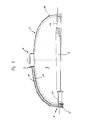
- FIG. 1 shows a building for the arrangement above a swimming pool 1 (see Figures 2 and 3) shown in side view.
- the building consists of one Dome 2, which is formed substantially spherical segment-shaped.
- the dome 2 has a first section 3 and a second section 4.
- the first section 3 is connected to a foundation 5, which is annular and in the interior of which the swimming pool 1 is arranged.
- the second section 4 is movable relative to the first section 3 on the pivot bearing 7 arranged, wherein the second portion 4 is guided in a guideway 8, the Part of the foundation 5 is.
- the shape of the second section 4 corresponds to the shape of the first Section 3, wherein the second section 4 along the outer contour of the first Section 3 is displaceable.
- the second section 4 closes an opening 9 of the first section 3, wherein the opening 9 extends over a circular arc of 120 ° of the dome 2.
- the second section 4 from the foundation 5 to the ridge area 6, i. until the pivot bearing 7 extends, so that when moving the second section 4 and release the opening 9 an embodiment of the dome 2 above the swimming pool 1 such that a predominant part of the swimming pool 1 is not covered by the dome 2.
- the dome 2 consists of a plurality of evenly spaced from each other arranged Trägem 11, which are designed as trusses. These Trusses will be described in more detail below.
- wall elements 12 made of glass or plastic arranged, which is at least predominantly translucent and transparent are.
- the second section 4 is divided into two segments 13 of equal size, which are in opposite directions when opening and closing the opening 9.
- the segments 13 are connected to each other such that the movement of the one Segmentes 13 is transferred to the other segment 13.
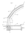
- the guideway 8 which in cross-section U-shaped is formed and in which a guide member 14 of the second section. 4 intervenes.
- a rack is arranged with the one Gear meshes, which is driven by an electric motor.
- the guideway 8 is shown in detail. It can be seen that the first section 3 of the dome 2 rests on the foundation 5 and with this connected is. The second section 4 is supported by the guide element 14 on the surface of the foundation 5 from, wherein the guide member 14, for example can be designed as a wheel or ball.
- the carrier 11 shown in Figure 4 consist of several different trained truss elements that riveted together, bolted or are welded. Each carrier 11 is arcuate section-shaped and ends in the ridge region 6 of the dome 2, each carrier 11 attached to the pivot bearing 7 is.
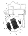
- FIG. 5 shows an embodiment of the building according to the invention with the Dome 2 in combination with outbuildings 20, which have a variety of facilities for leisure activities.
- the dome 2 in its the opening 9 diametrically opposite area another opening 21, over which the outbuilding 20 can be reached.
- the outbuilding 20 consists of modules that have different facilities, such as changing rooms, sanitary facilities, dining facilities, Have technical rooms, solariums, saunas or the like.
- the modular Construction of the outbuilding 20 allows a fast and cost-effective Creation of an appropriate leisure facility, in a simple way to the requirements the operator is customizable, in which the modules with the individual Components are selected and assembled.
Landscapes
- Engineering & Computer Science (AREA)
- Architecture (AREA)
- Civil Engineering (AREA)
- Structural Engineering (AREA)
- Physics & Mathematics (AREA)
- Electromagnetism (AREA)
- Tents Or Canopies (AREA)
Abstract
Description
- Figur 1
- ein Gebäude in Seitenansicht;
- Figur 2
- das Gebäude gemäß Figur 1 im Querschnitt;
- Figur 3
- das Gebäude gemäß den Figuren 1 und 2 in einer Draufsicht;
- Figur 4
- eine Schnittansicht eines Abschnitts des Gebäudes gemäß den Figuren 1 bis 3 in Richtung des Pfeils IV in Figur 3 und
- Figur 5
- eine Draufsicht auf ein Schwimmbad mit einem Gebäude gemäß den Figuren 1 bis 4 und daran angeschlossene Nebengebäude.
Claims (14)
- Gebäude für die Anordnung über einem Schwimmbecken (1), mit einem Fundament (5) und einer auf dem Fundament (5) angeordneten Kuppel (2), die aus einem feststehenden, mit dem Fundament (5) verbundenen ersten Abschnitt (3) und zumindest einem zweiten Abschnitt (4) besteht, welcher zweite Abschnitt (4) relativ zum ersten Abschnitt (3) entlang dessen Außen- oder Innenkontur verschiebbar ist und eine Öffnung (9) der Kuppel (2) öffnet oder verschließt, wobei die Kuppel (2) im wesentlichen halbkugel- oder kugelabschnittförmig ausgebildet ist und sich die Öffnung (9) über einem Kreisbogen von zumindest 90°, insbesondere zwischen 90° und 180° erstreckt, und wobei sich der zweite Abschnitt (4) vom Firstbereich (6) bis zum Fundament (5) erstreckt.
- Gebäude nach Anspruch 1,
dadurch gekennzeichnet, dass der zweite Abschnitt (4) in zwei Segmente (13) unterteilt ist, die gegenläufig bewegbar sind. - Gebäude nach Anspruch 2,
dadurch gekennzeichnet, dass die Segmente (13) miteinander verbunden sind, so dass die Segmente (13) gleichzeitig oder getrennt voneinander bewegbar sind. - Gebäude nach Anspruch 3,
dadurch gekennzeichnet, dass die Segmente (13) über einen Seilzug, eine Kette oder auch eine Kombination aus zumindest einer Zahnstange und zumindest einem angetriebenen Zahnrad pro Segment (13) des zweiten Abschnitts (4) miteinander verbunden sind. - Gebäude nach Anspruch 1,
dadurch gekennzeichnet, dass der zweite Abschnitt (4) elektromotorisch angetrieben ist. - Gebäude nach Anspruch 1,
dadurch gekennzeichnet, dass der zweite Abschnitt (4) auf einer Führungsbahn (8) geführt ist, die Bestandteil des Fundaments (5) ist. - Gebäude nach Anspruch 1,
dadurch gekennzeichnet, dass beide Abschnitte (3, 4) zumindest in einem Teilbereich transparente Wandelemente (12) aufweisen, wobei der Teilbereich unmittelbar oberhalb des Fundaments (5) angeordnet ist und eine Höhe von zumindest 2 m, vorzugsweise 2,5 m aufweist. - Gebäude nach Anspruch 1,
dadurch gekennzeichnet, dass die Kuppel (2) oberhalb eines transparenten Teilbereichs eine Wärme- und/oder Schalldämmschicht aufweist, die aus einzelnen Elementen besteht, die zwischen Trägem (11) angeordnet sind, wobei im Firstbereich zumindest ein Beleuchtungselement, vorzugsweise in Form eines transparenten, lichtdurchlässigen Flächenelementes vorgesehen ist. - Gebäude nach Anspruch 1,
dadurch gekennzeichnet, dass die Kuppel (2) in einem der mit dem zweiten Abschnitt (4) verschließbaren Öffnung (9) diametral gegenüberliegenden Bereich zumindest eine weitere Öffnung (21) mit einem Anschluss an ein Nebengebäude (20) aufweist. - Gebäude nach Anspruch 8,
dadurch gekennzeichnet, dass das Nebengebäude (20) aus einem oder mehreren Modulen besteht. - Gebäude nach Anspruch 1,
dadurch gekennzeichnet, dass die Kuppel (2) aus mehreren in gleichmäßigem Abstand zueinander angeordneten Trägem (11) besteht, zwischen denen Wandelemente (12) angeordnet sind. - Gebäude nach Anspruch 10,
dadurch gekennzeichnet, dass die Träger (11) als Fachwerkträger aus Metall, insbesondere verzinktem Stahl und/oder Aluminium ausgebildet sind. - Gebäude nach Anspruch 10,
dadurch gekennzeichnet, dass die Wandelemente (12) zumindest teilweise lichtdurchlässig und/oder transparent sind. - Gebäude nach Anspruch 1,
dadurch gekennzeichnet, dass der erste Abschnitt (3) im Firstbereich (6) ein Lager (7) aufweist, in dem der zweite Abschnitt (4) drehbar gelagert ist.
Applications Claiming Priority (6)
| Application Number | Priority Date | Filing Date | Title |
|---|---|---|---|
| DE202004002025 | 2004-02-10 | ||
| DE202004002025U | 2004-02-10 | ||
| DE102004014574 | 2004-03-25 | ||
| DE102004014574 | 2004-03-25 | ||
| DE102004016274 | 2004-04-02 | ||
| DE102004016274A DE102004016274B4 (de) | 2004-02-10 | 2004-04-02 | Gebäude für die Anordnung über einem Schwimmbecken |
Publications (2)
| Publication Number | Publication Date |
|---|---|
| EP1564348A1 true EP1564348A1 (de) | 2005-08-17 |
| EP1564348B1 EP1564348B1 (de) | 2014-08-20 |
Family
ID=34704643
Family Applications (1)
| Application Number | Title | Priority Date | Filing Date |
|---|---|---|---|
| EP20050002467 Expired - Lifetime EP1564348B1 (de) | 2004-02-10 | 2005-02-05 | Gebäude für die Anordnung über einem Schwimmbecken |
Country Status (1)
| Country | Link |
|---|---|
| EP (1) | EP1564348B1 (de) |
Cited By (5)
| Publication number | Priority date | Publication date | Assignee | Title |
|---|---|---|---|---|
| WO2007040414A1 (en) | 2005-10-05 | 2007-04-12 | Alukov Hz Spol.S.R.O. | Enclosure, especially spa enclosure |
| CN101278100B (zh) * | 2005-10-05 | 2012-05-02 | 亚鲁克瓦Hz公司 | 游泳池室 |
| CN105040882A (zh) * | 2015-08-03 | 2015-11-11 | 南通苏驰建设工程有限公司 | 对称式旋转开合屋顶 |
| WO2016165084A1 (en) * | 2015-04-15 | 2016-10-20 | Xiaoping Sun | Mold for making units of a dome structure and method of using the same |
| CN110258775A (zh) * | 2019-06-28 | 2019-09-20 | 佛山柔茂金属有限公司 | 一种阳光房 |
Citations (5)
| Publication number | Priority date | Publication date | Assignee | Title |
|---|---|---|---|---|
| DE1929366A1 (de) * | 1969-06-10 | 1970-12-23 | Ibaco Bau Coordinierungsgmbh & | Hallenbad |
| US4246663A (en) | 1979-09-17 | 1981-01-27 | Aragona Anthony J | Hot tub cover |
| FR2719618A1 (fr) | 1994-05-09 | 1995-11-10 | Vettor Jean Jacques | Dispositif pour abriter une piscine ou tout autre espace ou terrain de sport, en forme de coupole et ouvrable sur 240 degrés. |
| DE19520546A1 (de) | 1995-06-06 | 1996-12-12 | Kroeger Anita | Abdeckung für ein etwa kreisrundes Schwimmbecken |
| FR2744749A1 (fr) | 1996-02-13 | 1997-08-14 | Renneteau Claude | Structure modulaire de batiment de piscine |
-
2005
- 2005-02-05 EP EP20050002467 patent/EP1564348B1/de not_active Expired - Lifetime
Patent Citations (5)
| Publication number | Priority date | Publication date | Assignee | Title |
|---|---|---|---|---|
| DE1929366A1 (de) * | 1969-06-10 | 1970-12-23 | Ibaco Bau Coordinierungsgmbh & | Hallenbad |
| US4246663A (en) | 1979-09-17 | 1981-01-27 | Aragona Anthony J | Hot tub cover |
| FR2719618A1 (fr) | 1994-05-09 | 1995-11-10 | Vettor Jean Jacques | Dispositif pour abriter une piscine ou tout autre espace ou terrain de sport, en forme de coupole et ouvrable sur 240 degrés. |
| DE19520546A1 (de) | 1995-06-06 | 1996-12-12 | Kroeger Anita | Abdeckung für ein etwa kreisrundes Schwimmbecken |
| FR2744749A1 (fr) | 1996-02-13 | 1997-08-14 | Renneteau Claude | Structure modulaire de batiment de piscine |
Non-Patent Citations (1)
| Title |
|---|
| "TOURNESOL", BATIR, LE BATIMENT. PARIS, FR, vol. 27, 1 December 1973 (1973-12-01), pages 63 - 67, XP002015675 * |
Cited By (7)
| Publication number | Priority date | Publication date | Assignee | Title |
|---|---|---|---|---|
| WO2007040414A1 (en) | 2005-10-05 | 2007-04-12 | Alukov Hz Spol.S.R.O. | Enclosure, especially spa enclosure |
| RU2401369C2 (ru) * | 2005-10-05 | 2010-10-10 | Компания "АЛУКОВ ХЗ Спол.с.р.о" | Павильон, в том числе для приема водных процедур |
| AU2006297932B2 (en) * | 2005-10-05 | 2011-08-18 | Alukov Hz Spol.S.R.O. | Enclosure, especially spa enclosure |
| CN101278100B (zh) * | 2005-10-05 | 2012-05-02 | 亚鲁克瓦Hz公司 | 游泳池室 |
| WO2016165084A1 (en) * | 2015-04-15 | 2016-10-20 | Xiaoping Sun | Mold for making units of a dome structure and method of using the same |
| CN105040882A (zh) * | 2015-08-03 | 2015-11-11 | 南通苏驰建设工程有限公司 | 对称式旋转开合屋顶 |
| CN110258775A (zh) * | 2019-06-28 | 2019-09-20 | 佛山柔茂金属有限公司 | 一种阳光房 |
Also Published As
| Publication number | Publication date |
|---|---|
| EP1564348B1 (de) | 2014-08-20 |
Similar Documents
| Publication | Publication Date | Title |
|---|---|---|
| DE3938955A1 (de) | Bewegliches dach | |
| EP1564348B1 (de) | Gebäude für die Anordnung über einem Schwimmbecken | |
| DE4025711C2 (de) | ||
| DE4215742C2 (de) | Parkhaus mit einer doppelgängigen Wendelrampe | |
| DE102004016274B4 (de) | Gebäude für die Anordnung über einem Schwimmbecken | |
| EP2045418A2 (de) | Gebäude | |
| DE202004005237U1 (de) | Gebäude für die Anordnung über einem Schwimmbecken | |
| DE102007053465B4 (de) | Überdachung | |
| EP0870523A2 (de) | Skate-Anlage aus Einzelelementen | |
| DE69913446T2 (de) | Wohngebäude mit veränderbarem Schwimmbad | |
| DE4018746C2 (de) | Mehrfachgarage | |
| DE2151929A1 (de) | Transportable schwimmhalle | |
| DE3149971A1 (de) | "garage fuer kraftfahrzeuge" | |
| DE102005007475B3 (de) | Personenlift | |
| DE19930679A1 (de) | Begehbares Wandelement | |
| WO1994020705A1 (de) | Mobiles veranstaltungszentrum mit einem aus stahlelementen bestehenden traggerippe | |
| DE2302145B2 (de) | Einrichtung für eine Mehrfachgarage | |
| DE19734398B4 (de) | Karusselltür | |
| DE29824132U1 (de) | Wintergartenbausatz in Pavillonform | |
| DE2021883A1 (de) | Verfahrbare UEberdachung | |
| DE2113534C3 (de) | Hallenartige, ein- und ausfahrbare Überdachung, insbesondere für Schwimmbäder oder Sportplätze | |
| DE2242672C3 (de) | Nichtfaltbares Schiebedach, insbesondere zur Abdeckung von Dachausschnitten | |
| DE9316166U1 (de) | Garage | |
| DE2927985A1 (de) | Rollhalle fuer schwimmbaeder | |
| DE9107717U1 (de) | Natursolarium mit erweitertem Anwendungsbereich |
Legal Events
| Date | Code | Title | Description |
|---|---|---|---|
| PUAI | Public reference made under article 153(3) epc to a published international application that has entered the european phase |
Free format text: ORIGINAL CODE: 0009012 |
|
| AK | Designated contracting states |
Kind code of ref document: A1 Designated state(s): AT BE BG CH CY CZ DE DK EE ES FI FR GB GR HU IE IS IT LI LT LU MC NL PL PT RO SE SI SK TR |
|
| AX | Request for extension of the european patent |
Extension state: AL BA HR LV MK YU |
|
| 17P | Request for examination filed |
Effective date: 20060217 |
|
| AKX | Designation fees paid |
Designated state(s): AT BE BG CH CY CZ DE DK EE ES FI FR GB GR HU IE IS IT LI LT LU MC NL PL PT RO SE SI SK TR |
|
| AXX | Extension fees paid |
Extension state: LV Payment date: 20060217 |
|
| 17Q | First examination report despatched |
Effective date: 20110207 |
|
| REG | Reference to a national code |
Ref country code: DE Ref legal event code: R079 Ref document number: 502005014484 Country of ref document: DE Free format text: PREVIOUS MAIN CLASS: E04H0004160000 Ipc: E04H0003160000 |
|
| GRAP | Despatch of communication of intention to grant a patent |
Free format text: ORIGINAL CODE: EPIDOSNIGR1 |
|
| RIC1 | Information provided on ipc code assigned before grant |
Ipc: E04H 3/16 20060101AFI20140131BHEP Ipc: E04B 7/16 20060101ALI20140131BHEP |
|
| INTG | Intention to grant announced |
Effective date: 20140304 |
|
| GRAS | Grant fee paid |
Free format text: ORIGINAL CODE: EPIDOSNIGR3 |
|
| GRAA | (expected) grant |
Free format text: ORIGINAL CODE: 0009210 |
|
| AK | Designated contracting states |
Kind code of ref document: B1 Designated state(s): AT BE BG CH CY CZ DE DK EE ES FI FR GB GR HU IE IS IT LI LT LU MC NL PL PT RO SE SI SK TR |
|
| AX | Request for extension of the european patent |
Extension state: LV |
|
| REG | Reference to a national code |
Ref country code: GB Ref legal event code: FG4D Free format text: NOT ENGLISH |
|
| REG | Reference to a national code |
Ref country code: CH Ref legal event code: EP |
|
| REG | Reference to a national code |
Ref country code: AT Ref legal event code: REF Ref document number: 683570 Country of ref document: AT Kind code of ref document: T Effective date: 20140915 |
|
| REG | Reference to a national code |
Ref country code: IE Ref legal event code: FG4D Free format text: LANGUAGE OF EP DOCUMENT: GERMAN |
|
| REG | Reference to a national code |
Ref country code: DE Ref legal event code: R096 Ref document number: 502005014484 Country of ref document: DE Effective date: 20140925 |
|
| REG | Reference to a national code |
Ref country code: NL Ref legal event code: VDEP Effective date: 20140820 |
|
| REG | Reference to a national code |
Ref country code: LT Ref legal event code: MG4D |
|
| PG25 | Lapsed in a contracting state [announced via postgrant information from national office to epo] |
Ref country code: SE Free format text: LAPSE BECAUSE OF FAILURE TO SUBMIT A TRANSLATION OF THE DESCRIPTION OR TO PAY THE FEE WITHIN THE PRESCRIBED TIME-LIMIT Effective date: 20140820 Ref country code: ES Free format text: LAPSE BECAUSE OF FAILURE TO SUBMIT A TRANSLATION OF THE DESCRIPTION OR TO PAY THE FEE WITHIN THE PRESCRIBED TIME-LIMIT Effective date: 20140820 Ref country code: LT Free format text: LAPSE BECAUSE OF FAILURE TO SUBMIT A TRANSLATION OF THE DESCRIPTION OR TO PAY THE FEE WITHIN THE PRESCRIBED TIME-LIMIT Effective date: 20140820 Ref country code: BG Free format text: LAPSE BECAUSE OF FAILURE TO SUBMIT A TRANSLATION OF THE DESCRIPTION OR TO PAY THE FEE WITHIN THE PRESCRIBED TIME-LIMIT Effective date: 20141120 Ref country code: GR Free format text: LAPSE BECAUSE OF FAILURE TO SUBMIT A TRANSLATION OF THE DESCRIPTION OR TO PAY THE FEE WITHIN THE PRESCRIBED TIME-LIMIT Effective date: 20141121 Ref country code: PT Free format text: LAPSE BECAUSE OF FAILURE TO SUBMIT A TRANSLATION OF THE DESCRIPTION OR TO PAY THE FEE WITHIN THE PRESCRIBED TIME-LIMIT Effective date: 20141222 Ref country code: FI Free format text: LAPSE BECAUSE OF FAILURE TO SUBMIT A TRANSLATION OF THE DESCRIPTION OR TO PAY THE FEE WITHIN THE PRESCRIBED TIME-LIMIT Effective date: 20140820 |
|
| PG25 | Lapsed in a contracting state [announced via postgrant information from national office to epo] |
Ref country code: IS Free format text: LAPSE BECAUSE OF FAILURE TO SUBMIT A TRANSLATION OF THE DESCRIPTION OR TO PAY THE FEE WITHIN THE PRESCRIBED TIME-LIMIT Effective date: 20141220 |
|
| PG25 | Lapsed in a contracting state [announced via postgrant information from national office to epo] |
Ref country code: NL Free format text: LAPSE BECAUSE OF FAILURE TO SUBMIT A TRANSLATION OF THE DESCRIPTION OR TO PAY THE FEE WITHIN THE PRESCRIBED TIME-LIMIT Effective date: 20140820 |
|
| PG25 | Lapsed in a contracting state [announced via postgrant information from national office to epo] |
Ref country code: RO Free format text: LAPSE BECAUSE OF FAILURE TO SUBMIT A TRANSLATION OF THE DESCRIPTION OR TO PAY THE FEE WITHIN THE PRESCRIBED TIME-LIMIT Effective date: 20140820 Ref country code: IT Free format text: LAPSE BECAUSE OF FAILURE TO SUBMIT A TRANSLATION OF THE DESCRIPTION OR TO PAY THE FEE WITHIN THE PRESCRIBED TIME-LIMIT Effective date: 20140820 Ref country code: DK Free format text: LAPSE BECAUSE OF FAILURE TO SUBMIT A TRANSLATION OF THE DESCRIPTION OR TO PAY THE FEE WITHIN THE PRESCRIBED TIME-LIMIT Effective date: 20140820 Ref country code: CZ Free format text: LAPSE BECAUSE OF FAILURE TO SUBMIT A TRANSLATION OF THE DESCRIPTION OR TO PAY THE FEE WITHIN THE PRESCRIBED TIME-LIMIT Effective date: 20140820 Ref country code: EE Free format text: LAPSE BECAUSE OF FAILURE TO SUBMIT A TRANSLATION OF THE DESCRIPTION OR TO PAY THE FEE WITHIN THE PRESCRIBED TIME-LIMIT Effective date: 20140820 Ref country code: SK Free format text: LAPSE BECAUSE OF FAILURE TO SUBMIT A TRANSLATION OF THE DESCRIPTION OR TO PAY THE FEE WITHIN THE PRESCRIBED TIME-LIMIT Effective date: 20140820 |
|
| REG | Reference to a national code |
Ref country code: DE Ref legal event code: R097 Ref document number: 502005014484 Country of ref document: DE |
|
| PG25 | Lapsed in a contracting state [announced via postgrant information from national office to epo] |
Ref country code: PL Free format text: LAPSE BECAUSE OF FAILURE TO SUBMIT A TRANSLATION OF THE DESCRIPTION OR TO PAY THE FEE WITHIN THE PRESCRIBED TIME-LIMIT Effective date: 20140820 |
|
| PLBE | No opposition filed within time limit |
Free format text: ORIGINAL CODE: 0009261 |
|
| STAA | Information on the status of an ep patent application or granted ep patent |
Free format text: STATUS: NO OPPOSITION FILED WITHIN TIME LIMIT |
|
| PG25 | Lapsed in a contracting state [announced via postgrant information from national office to epo] |
Ref country code: BE Free format text: LAPSE BECAUSE OF NON-PAYMENT OF DUE FEES Effective date: 20150228 |
|
| 26N | No opposition filed |
Effective date: 20150521 |
|
| PG25 | Lapsed in a contracting state [announced via postgrant information from national office to epo] |
Ref country code: LU Free format text: LAPSE BECAUSE OF FAILURE TO SUBMIT A TRANSLATION OF THE DESCRIPTION OR TO PAY THE FEE WITHIN THE PRESCRIBED TIME-LIMIT Effective date: 20150205 |
|
| REG | Reference to a national code |
Ref country code: CH Ref legal event code: PL |
|
| GBPC | Gb: european patent ceased through non-payment of renewal fee |
Effective date: 20150205 |
|
| PG25 | Lapsed in a contracting state [announced via postgrant information from national office to epo] |
Ref country code: MC Free format text: LAPSE BECAUSE OF FAILURE TO SUBMIT A TRANSLATION OF THE DESCRIPTION OR TO PAY THE FEE WITHIN THE PRESCRIBED TIME-LIMIT Effective date: 20140820 Ref country code: CH Free format text: LAPSE BECAUSE OF NON-PAYMENT OF DUE FEES Effective date: 20150228 Ref country code: LI Free format text: LAPSE BECAUSE OF NON-PAYMENT OF DUE FEES Effective date: 20150228 |
|
| REG | Reference to a national code |
Ref country code: IE Ref legal event code: MM4A |
|
| PG25 | Lapsed in a contracting state [announced via postgrant information from national office to epo] |
Ref country code: SI Free format text: LAPSE BECAUSE OF FAILURE TO SUBMIT A TRANSLATION OF THE DESCRIPTION OR TO PAY THE FEE WITHIN THE PRESCRIBED TIME-LIMIT Effective date: 20140820 |
|
| PG25 | Lapsed in a contracting state [announced via postgrant information from national office to epo] |
Ref country code: IE Free format text: LAPSE BECAUSE OF NON-PAYMENT OF DUE FEES Effective date: 20150205 Ref country code: GB Free format text: LAPSE BECAUSE OF NON-PAYMENT OF DUE FEES Effective date: 20150205 |
|
| REG | Reference to a national code |
Ref country code: FR Ref legal event code: PLFP Year of fee payment: 12 |
|
| PGFP | Annual fee paid to national office [announced via postgrant information from national office to epo] |
Ref country code: AT Payment date: 20160229 Year of fee payment: 12 |
|
| PGFP | Annual fee paid to national office [announced via postgrant information from national office to epo] |
Ref country code: DE Payment date: 20160429 Year of fee payment: 12 |
|
| REG | Reference to a national code |
Ref country code: FR Ref legal event code: PLFP Year of fee payment: 13 |
|
| PG25 | Lapsed in a contracting state [announced via postgrant information from national office to epo] |
Ref country code: HU Free format text: LAPSE BECAUSE OF FAILURE TO SUBMIT A TRANSLATION OF THE DESCRIPTION OR TO PAY THE FEE WITHIN THE PRESCRIBED TIME-LIMIT; INVALID AB INITIO Effective date: 20050205 |
|
| PG25 | Lapsed in a contracting state [announced via postgrant information from national office to epo] |
Ref country code: CY Free format text: LAPSE BECAUSE OF FAILURE TO SUBMIT A TRANSLATION OF THE DESCRIPTION OR TO PAY THE FEE WITHIN THE PRESCRIBED TIME-LIMIT Effective date: 20140820 |
|
| PG25 | Lapsed in a contracting state [announced via postgrant information from national office to epo] |
Ref country code: TR Free format text: LAPSE BECAUSE OF FAILURE TO SUBMIT A TRANSLATION OF THE DESCRIPTION OR TO PAY THE FEE WITHIN THE PRESCRIBED TIME-LIMIT Effective date: 20140820 |
|
| REG | Reference to a national code |
Ref country code: DE Ref legal event code: R119 Ref document number: 502005014484 Country of ref document: DE |
|
| REG | Reference to a national code |
Ref country code: AT Ref legal event code: MM01 Ref document number: 683570 Country of ref document: AT Kind code of ref document: T Effective date: 20170205 |
|
| PG25 | Lapsed in a contracting state [announced via postgrant information from national office to epo] |
Ref country code: AT Free format text: LAPSE BECAUSE OF NON-PAYMENT OF DUE FEES Effective date: 20170205 |
|
| PG25 | Lapsed in a contracting state [announced via postgrant information from national office to epo] |
Ref country code: DE Free format text: LAPSE BECAUSE OF NON-PAYMENT OF DUE FEES Effective date: 20170901 |
|
| REG | Reference to a national code |
Ref country code: FR Ref legal event code: PLFP Year of fee payment: 14 |
|
| PGFP | Annual fee paid to national office [announced via postgrant information from national office to epo] |
Ref country code: FR Payment date: 20190227 Year of fee payment: 15 |
|
| PG25 | Lapsed in a contracting state [announced via postgrant information from national office to epo] |
Ref country code: FR Free format text: LAPSE BECAUSE OF NON-PAYMENT OF DUE FEES Effective date: 20200229 |