EP1564348B1 - Gebäude für die Anordnung über einem Schwimmbecken - Google Patents
Gebäude für die Anordnung über einem Schwimmbecken Download PDFInfo
- Publication number
- EP1564348B1 EP1564348B1 EP20050002467 EP05002467A EP1564348B1 EP 1564348 B1 EP1564348 B1 EP 1564348B1 EP 20050002467 EP20050002467 EP 20050002467 EP 05002467 A EP05002467 A EP 05002467A EP 1564348 B1 EP1564348 B1 EP 1564348B1
- Authority
- EP
- European Patent Office
- Prior art keywords
- section
- building according
- foundation
- building
- segments
- Prior art date
- Legal status (The legal status is an assumption and is not a legal conclusion. Google has not performed a legal analysis and makes no representation as to the accuracy of the status listed.)
- Expired - Lifetime
Links
Images
Classifications
-
- E—FIXED CONSTRUCTIONS
- E04—BUILDING
- E04H—BUILDINGS OR LIKE STRUCTURES FOR PARTICULAR PURPOSES; SWIMMING OR SPLASH BATHS OR POOLS; MASTS; FENCING; TENTS OR CANOPIES, IN GENERAL
- E04H3/00—Buildings or groups of buildings for public or similar purposes; Institutions, e.g. infirmaries or prisons
- E04H3/10—Buildings or groups of buildings for public or similar purposes; Institutions, e.g. infirmaries or prisons for meetings, entertainments, or sports
- E04H3/14—Gymnasiums; Other sporting buildings
- E04H3/16—Gymnasiums; Other sporting buildings for swimming
- E04H3/165—Gymnasiums; Other sporting buildings for swimming having movable parts
-
- E—FIXED CONSTRUCTIONS
- E04—BUILDING
- E04B—GENERAL BUILDING CONSTRUCTIONS; WALLS, e.g. PARTITIONS; ROOFS; FLOORS; CEILINGS; INSULATION OR OTHER PROTECTION OF BUILDINGS
- E04B7/00—Roofs; Roof construction with regard to insulation
- E04B7/16—Roof structures with movable roof parts
- E04B7/163—Roof structures with movable roof parts characterised by a pivoting movement of the movable roof parts
Definitions
- the invention relates to a building for the arrangement above a swimming pool, with a foundation and a dome arranged on the foundation, which consists of a fixed, connected to the foundation first portion and a second portion, which second portion relative to the first portion along the outside slidably and subdivided into two segments which are movable in opposite directions and open or close an opening of the dome, wherein the dome is formed substantially hemispherical or spherical segment-shaped, wherein the opening over a circular arc of at least 90 °, in particular between Extends 90 ° and 180 °.
- Such buildings are known from the prior art. Usually, outdoor pools are differentiated from indoor pools. For outdoor pools, a building for the arrangement above a swimming pool is not provided. In contrast, the swimming pools in indoor swimming pools are arranged in a building, which is usually made in conventional construction, i. bricked or cast walls with windows and a roof. In addition, in smaller, usually privately used swimming pool building known that can be arranged over a swimming pool. In general, such buildings have individual segments which are telescopically connected to each other, so that the building can be arranged above the swimming pool or the segments can be pushed into each other, so that the pool is then accessible.
- a cover for a roughly circular swimming pool known.
- This cover is formed two or more shell, the movable shells are guided on each separately running rails to ensure mobility.
- the cover is arranged on the upper edge of an approximately circular swimming pool and is connected via anchors to the ground.
- a foundation according to the invention can not be deduced from this prior art. Also offers this constructive Design of a cover no way to use the area around the pool in the sense of an indoor swimming pool for the stay of persons or for the provision of objects, such as relaxation loungers.
- the disclosure FR 2 719 618 A1 a cover for a swimming pool, said cover dome-shaped and consists of a support member having a bearing on which a plurality of movable elements are mounted relative to a fixed element.
- a generic building is from the FR 2 744 749 A known.
- This known building is intended for the arrangement over a swimming pool, wherein a fixed dome is provided with an opening which can be opened and closed by means of two movably mounted sections.
- the movably mounted sections are designed for opening and closing an opening provided exclusively in the roof area of the spherical section-shaped building and mounted on rails which rest on horizontal struts, which in turn are arranged on vertical supports above the floor.
- the invention has the object , a generic building for the arrangement above a swimming pool in such a way that a multi-functional swimming pool is achieved, which regardless of the weather conditions throughout the year available is, in particular, should be possible to use as a swimming pool or in frereibadähnmaschine way.
- An inventive building thus has the advantage that it completely covers a swimming pool in that the second section closes the opening of the dome.
- the swimming pool in the form of an indoor pool can be used all year round.
- the opening of the dome is opened, so that a substantial part of the dome can be opened by the configuration of the opening and the second section that also a substantial part of the swimming pool arranged in the building is freely accessible.
- the opening of the dome allows the use of solar energy to heat the interior and water in the pool.
- the second section is guided on a guideway, which is part of the foundation.
- the second section is supported on this guideway, wherein the second section or its segments, for example, on the guideway resting rolling elements, such as balls or wheels, of which, for example, some can be driven.
- the guideway may also include a rack in which one or more driven gears mesh.
- a swimming pool can thus be used as an outdoor pool in the warm summer months and as an indoor pool in the colder autumn and spring months and the cold winter months. This results in a longer period of use of such swimming pools, so far
- the building can be restructured for example in existing outdoor pools in a simple manner by arranging the foundation and the dome to a multi-functional swimming pool.
- financial relief for the operators of an open-air swimming pool results, the success of which depends primarily on the weather, ie the temperatures in spring and in summer and in autumn.
- Particularly advantageous here is the large opening of the dome. In the case of a hemispherical dome, the opening state results in an opening area of up to one half, so that the users of the swimming pool receive a feeling comparable to the use of an outdoor pool.
- the second section is divided into two segments which are movable in opposite directions.
- This embodiment has the advantage that the division of the second section into two segments leads to a reduction of the elements to be displaced. As a result, the force required for the displacement of these elements, namely the second section is reduced.
- the division of the second section into two segments also offers the advantage that only a portion of the opening is opened. Of course, it is also possible to divide the second section into more than two segments, which are then individually movable.
- a development of this embodiment provides that the segments are connected to each other, so that the segments are movable simultaneously. If, for example, a segment is divided from the closed position into the open position in the case of a second section divided into two segments, then the second segments are also transferred in opposite directions to the open position by the connection of the two segments. The same is of course also possible in the embodiment of the second section with a division into several segments.
- the thus simultaneously moving segments are preferably via a cable, a chain or a combination of rack and driven Gears connected together.
- each segment drive motors which are preferably controllable via a common control.
- a section-wise method of the segments may be necessary and / or advantageous, for example, for cleaning purposes.
- An electric motor drive has the additional advantage that the movement is very even. Electromotive also larger segments of the second section can be moved without much effort beyond.
- the two sections have transparent wall elements at least in a partial region, wherein the partial region is arranged directly above the foundation and has a height of at least 2 m.
- the partial region is arranged directly above the foundation and has a height of at least 2 m.
- the dome has in one of the closable with the second section opening diametrically opposite area at least one further opening with a connection to an outbuilding.
- the outbuilding according to a further feature of the invention consists of one or more modules.
- the technical equipment for the swimming pool ie for the treatment and heating of the water in the swimming pool be housed.
- the outbuilding can have further facilities, such as sauna, fitness areas, wellness areas or the like, and in particular also be designed with the required changing rooms, sanitary facilities and with catering establishments.
- the modular design of the outbuildings or outbuildings allows a simple and cost-effective adaptation of the building with the outbuilding to the requirements of an existing outdoor pool. For example, this can be converted into an all-year usable pool in a short time and at low cost, a pool usually existing only from corresponding swimming pool in which the user can also find a variety of other facilities, the economy of the swimming pool by increasing the attractiveness improved his offer.
- the dome consists of a plurality of equally spaced supports arranged, between which wall elements are arranged.
- the carriers are preferably designed as truss girders made of metal, in particular galvanized steel and / or aluminum.
- the carriers are connected to the foundation, which is circular.
- Such a foundation may for example have a diameter of 30 m to 40 m, in particular of 36 m, wherein the carrier are arranged in a central point in the ridge area converging.
- the wall elements between the carriers are translucent and preferably transparent, so that the natural solar radiation can be used both for heating the interior of the building and for illuminating the building over as long a period as possible. As a result, in particular energy savings for the heating and lighting of the building are achieved.
- the first portion in the ridge region has a bearing in which the second portion is rotatably mounted.
- This bearing can be designed both as a pivot bearing, as well as a turntable and also serves as a ridge-side attachment point for the carrier described above.
- Preferred is the use of a turntable with, for example, a diameter of 4 m.
- the second portion is therefore connected at one along the outer contour of the fixed portion on the outer surface and at one along the inner contour of the fixed portion on the inner surface of the turntable.
- a translucent plate is arranged, which can be set up for ventilation purposes, for example, electric motor.
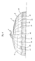
- FIG. 1 is a building for the arrangement above a swimming pool 1 (see. Figures 2 and 3 ) shown in side view.
- the building consists of a dome 2, which is essentially spherical segment-shaped.
- the dome 2 has a first portion 3 and a second portion 4.
- the first portion 3 is connected to a foundation 5, which is annular and in the interior of the swimming pool 1 is arranged.
- the dome 2 has a pivot bearing 7 in its ridge region 6.
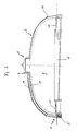
- the second portion 4 is arranged relative to the first portion 3 movable on the pivot bearing 7, wherein the second portion 4 is guided in a guide track 8, which is part of the foundation 5.
- the shape of the second portion 4 corresponds to the shape of the first portion 3, wherein the second portion 4 along the outer contour of the first portion 3 is displaceable.
- the second section 4 closes an opening 9 of the first section 3, wherein the opening 9 extends over a circular arc of 120 ° of the dome 2.
- the second section 4 starting from the foundation 5 to the ridge region 6, that extends to the pivot bearing 7, so that upon displacement of the second portion 4 and release the opening 9, an embodiment of the dome 2 above the pool 1 results in that a predominant part of the swimming pool 1 is not covered by the dome 2.
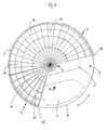
- the dome 2 consists of a plurality of uniformly spaced supports 11, which are designed as trusses. These trusses will be described in more detail below.
- wall elements 12 are arranged made of glass or plastic, which are at least predominantly translucent and transparent.
- the second section 4 is divided into two segments 13 of equal size, which are movable in opposite directions during opening and closing of the opening 9.
- the segments 13 are connected to each other such that the movement of the one segment 13 is transmitted to the other segment 13.
- the guideway 8 is shown, which is U-shaped in cross section and into which a guide element 14 of the second section 4 engages.
- a rack is arranged, with which a gear meshes, which is driven by an electric motor.
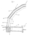
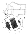
- FIG. 4 the guideway 8 is shown in detail. It can be seen that the first portion 3 of the dome 2 rests on the foundation 5 and is connected thereto.
- the second section 4 is supported on the guide element 14 on the surface of the foundation 5, wherein the guide member 14 may be formed, for example, as a wheel or ball.
- carrier 11 shown consist of several differently shaped truss elements that are riveted together, bolted or welded. Each carrier 11 is formed arcuate section-shaped and terminates in the ridge region 6 of the dome 2, each carrier 11 is attached to the pivot bearing 7.
- FIG. 5 shows an embodiment of the building according to the invention with the dome 2 in combination with outbuildings 20, which have a variety of facilities for recreational use.
- the dome 2 in its opening 9 diametrically opposite area on another opening 21 through which the outbuilding 20 is reached.
- the outbuilding 20 consists of modules that have different facilities, such as changing rooms, sanitary facilities, dining facilities, technical rooms, solariums, saunas or the like.
- the modular design of the outbuilding 20 allows a quick and inexpensive creation of a corresponding leisure facility, in a simple manner to the requirements the operator is customizable, in which the modules are selected and assembled with the individual components.
Landscapes
- Engineering & Computer Science (AREA)
- Architecture (AREA)
- Civil Engineering (AREA)
- Structural Engineering (AREA)
- Physics & Mathematics (AREA)
- Electromagnetism (AREA)
- Tents Or Canopies (AREA)
Description
- Die Erfindung betrifft ein Gebäude für die Anordnung über einem Schwimmbecken, mit einem Fundament und einer auf dem Fundament angeordneten Kuppel, die aus einem feststehenden, mit dem Fundament verbundenen ersten Abschnitt und einem zweiten Abschnitt besteht, welcher zweite Abschnitt relativ zum ersten Abschnitt entlang dessen Aussen- oder Innenkontur verschiebbar und in zwei Segmente unterteilt ist, die gegenläufig bewegbar sind und eine Öffnung der Kuppel öffnen oder verschließen, wobei die Kuppel im wesentlichen halbkugel- oder kugelabschnittförmig ausgebildet ist, wobei sich die Öffnung über einen Kreisbogen von zumindest 90°, insbesondere zwischen 90° und 180° erstreckt.
- Aus dem Stand der Technik sind derartige Gebäude bekannt. Üblicherweise werden Freibäder von Hallenbädern unterschieden. Bei Freibädern ist ein Gebäude für die Anordnung über einem Schwimmbecken nicht vorgesehen. Demgegenüber sind die Schwimmbecken bei Hallenbädern in einem Gebäude angeordnet, welches in der Regel in konventioneller Bauweise hergestellt wird, d.h. gemauerte oder gegossene Wände mit Fensterflächen und einem Dach aufweist. Darüber hinaus sind bei kleineren, in der Regel privat genutzten Schwimmbecken Gebäude bekannt, die über einem Schwimmbecken angeordnet werden können. In der Regel weisen derartige Gebäude einzelne Segmente auf, die teleskopartig miteinander verbunden sind, so dass das Gebäude über dem Schwimmbecken angeordnet werden kann bzw. die Segmente ineinander geschoben werden können, so dass das Schwimmbecken dann zugänglich ist.
- Aus der
DE 195 20 546 A1 ist eine Abdeckung für ein etwa kreisrundes Schwimmbecken bekannt. Diese Abdeckung ist zwei- oder mehrschalig ausgebildet, wobei die beweglichen Schalen auf jeweils separat ausgeführten Laufschienen geführt sind, um eine Beweglichkeit zu gewährleisten. Die Abdeckung ist auf dem oberen Rand eines etwa kreisrunden Schwimmbeckens angeordnet und wird über Anker mit dem Erdboden verbunden. Ein Fundament im Sinne der Erfindung ist aus diesem Stand der Technik nicht zu entnehmen. Auch bietet diese konstruktive Ausgestaltung einer Abdeckung keine Möglichkeit den Bereich um das Schwimmbecken im Sinne eines Hallenschwimmbades zum Aufenthalt von Personen oder zur Bereitstellung von Gegenständen, wie beispielsweise Ruheliegen zu nutzen. - Eine ähnliche Konstruktion ist aus der
US 4 246 663 A1 zu entnehmen. Dieser Stand der Technik offenbart bewegliche Segmente auf Rollen, die über einem Whirlpool angeordnet werden. Hierbei ist eine Grundplatte vorgesehen, die mit einem Abschnitt der Abdeckung verbunden ist, während der zweite Abschnitt relativ zum ersten Abschnitt und relativ zur Grundplatte bewegbar ist. Diesbezüglich weist dieser zweite Abschnitt Rollen auf, die ein einfaches Verschieben eines zweiten Abschnitts ermöglichen. - Weiterhin offenbart die
FR 2 719 618 A1 - Ein gattungsgemäßes Gebäude ist aus der
FR 2 744 749 A - Ausgehend von diesem Stand der Technik liegt der Erfindung die Aufgabe zugrunde, ein gattungsgemäßes Gebäude für die Anordnung über einem Schwimmbecken derart auszubilden, dass ein multifunktionales Schwimmbad erzielt wird, welches unabhängig von den Witterungseinflüssen ganzjährig nutzbar ist, wobei insbesondere auch eine Nutzung als Freibad oder in freibadähnlicher Weise möglich sein soll.
- Die Lösung dieser Aufgabenstellung sieht bei einem gattungsgemäßen Gebäude vor, dass sich der zweite Abschnitt vom Firstbereich bis zum Fundament erstreckt und dass die Segmente des zweiten Abschnitts auf einer Führungsbahn geführt sind, die Bestandteil des Fundaments ist und derart miteinander verbunden sind, dass die Segmente gleichzeitig oder getrennt voneinander bewegbar sind.
- Ein erfindungsgemäßes Gebäude hat somit den Vorteil, dass es ein Schwimmbecken vollständig dadurch abdeckt, dass der zweite Abschnitt die Öffnung der Kuppel verschließt. Im geschlossenen Zustand kann demzufolge das Schwimmbecken in Form eines Hallenbades ganzjährig genutzt werden. Wird der zweite Abschnitt relativ zum ersten Abschnitt entlang der Außen- und/oder Innenkontur des ersten Abschnitts verschoben, so wird die Öffnung der Kuppel geöffnet, so dass durch die Ausgestaltung der Öffnung und des zweiten Abschnitts ein wesentlicher Teil der Kuppel geöffnet werden kann, so dass auch ein wesentlicher Teil des in dem Gebäude angeordneten Schwimmbeckens frei zugänglich ist. Hierdurch wird der Eindruck eines Freibades erzielt. Gleichzeitig ermöglicht die Öffnung der Kuppel die Nutzung der Sonnenenergie zur Erwärmung des Innenraums und des Wassers im Schwimmbecken. Es ist ferner bei der Erfindung vorgesehen, dass der zweite Abschnitt auf einer Führungsbahn geführt ist, die Bestandteil des Fundaments ist. Der zweite Abschnitt stützt sich auf dieser Führungsbahn ab, wobei der zweite Abschnitt bzw. dessen Segmente beispielsweise auf der Führungsbahn aufliegende Rollelemente, wie Kugeln oder Räder aufweisen kann, von denen beispielsweise auch einige angetrieben werden können. Darüber hinaus kann die Führungsbahn auch eine Zahnstange aufweisen, in der ein oder mehrere angetriebene Zahnräder kämmen.
- Durch das erfindungsgemäße Gebäude kann ein Schwimmbecken somit in den warmen Sommermonaten als Freibad und in den kälteren Herbst- und Frühlingsmonaten sowie den kalten Wintermonaten als Hallenbad genutzt werden. Hierdurch ergibt sich eine längere Nutzungszeit derartiger Schwimmbecken, soweit das Gebäude beispielsweise bei bestehenden Freibädern in einfacher Weise durch Anordnung des Fundamentes und der Kuppel zu einem multifunktionalen Schwimmbad umstrukturiert werden kann. Hierdurch ergeben sich insbesondere auch finanzielle Entlastungen für die Betreiber eines Freibades, deren Erfolg in erster Linie von der Witterung, d.h. den Temperaturen im Frühjahr und im Sommer sowie im Herbst abhängig sind. Besonders vorteilhaft ist hierbei die große Öffnung der Kuppel. Bei einer halbkugelförmigen Kuppel ergibt sich im geöffneten Zustand ein Öffnungsbereich von bis zu einer Hälfte, so dass die Nutzer des Schwimmbeckens ein mit der Nutzung eines Freibades vergleichbares Gefühl erhalten.
- Nach einem weiteren Merkmal der Erfindung ist vorgesehen, dass der zweite Abschnitt in zwei Segmente unterteilt ist, die gegenläufig bewegbar sind. Diese Ausgestaltung hat den Vorteil, dass die Aufteilung des zweiten Abschnitts in zwei Segmente zu einer Verkleinerung der zu verschiebenden Elemente führt. Hierdurch wird der Kraftaufwand für die Verschiebung dieser Elemente, nämlich des zweiten Abschnitts verkleinert. Darüber hinaus bietet sich durch die Aufteilung des zweiten Abschnitts in zwei Segmente auch der Vorteil, dass nur ein Teilbereich der Öffnung geöffnet wird. Selbstverständlich besteht auch die Möglichkeit, den zweiten Abschnitt in mehr als zwei Segmente aufzuteilen, die dann einzeln bewegbar sind.
- Eine Weiterbildung dieser Ausgestaltung sieht vor, dass die Segmente miteinander verbunden sind, so dass die Segmente gleichzeitig bewegbar sind. Wird beispielsweise bei einem in zwei Segmente aufgeteilten zweiten Abschnitt ein Segment von der Schließstellung in die Öffnungsstellung überführt, so wird durch die Verbindung der beiden Segmente auch das zweite Segmente in gegenläufiger Bewegung in die Öffnungsstellung überführt. Gleiches ist selbstverständlich auch bei der Ausgestaltung des zweiten Abschnittes mit einer Aufteilung in mehrere Segmente möglich.
- Die derart gleichzeitig zu bewegenden Segmente sind vorzugsweise über einen Seilzug, eine Kette oder eine Kombination aus Zahnstange und angetriebenen Zahnrädern miteinander verbunden. Es bestehen aber auch andere Möglichkeiten, die gegenläufige Bewegung der zwei Segmente des zweiten Abschnitts auszuführen, beispielsweise durch an jedem Segment vorgesehene Antriebsmotoren, die vorzugsweise über eine gemeinsame Steuerung steuerbar sind. Selbstverständlich besteht auch die Möglichkeit, die Segmente getrennt voneinander zu bewegen und insbesondere stufenlos oder abschnittsweise zu verfahren. Ein abschnittsweises Verfahren der Segmente kann beispielsweise zu Reinigunsgzwecken erforderlich und/oder vorteilhaft sein.
- Demzufolge ist es vorteilhaft, den zweiten Abschnitt elektromotorisch anzutreiben. Ein elektromotorischer Antrieb hat darüber hinaus den Vorteil, dass der Bewegungsablauf sehr gleichmäßig erfolgt. Elektromotorisch können darüber hinaus auch größere Segmente des zweiten Abschnitts ohne großen Kraftaufwand bewegt werden.
- Vorzugsweise ist bei einer Weiterbildung des erfindungsgemäßen Gebäudes vorgesehen, dass die beiden Abschnitte zumindest in einem Teilbereich transparente Wandelemente aufweisen, wobei der Teilbereich unmittelbar oberhalb des Fundaments angeordnet ist und eine Höhe von zumindest 2 m aufweist. Bei dieser Ausgestaltung wird nicht nur eine gute Ausleuchtung des Gebäudes mit natürlichem Licht erzielt, sondern gleichzeitig auch dem Nutzer des Schwimmbeckens der Eindruck vermittelt, er befindet sich im Freien, da er ungehindert die Umgebung des Schwimmbeckens beobachten kann.
- Die Kuppel weist in einem der mit dem zweiten Abschnitt verschließbaren Öffnung diametral gegenüberliegenden Bereich zumindest eine weitere Öffnung mit einem Anschluss an ein Nebengebäude auf. Vorzugsweise besteht das Nebengebäude gemäß einem weiteren Merkmal der Erfindung aus einem oder mehreren Modulen.
- In dem Nebengebäude können die technischen Einrichtungen für das Schwimmbecken, d.h. für die Aufbereitung und Erwärmung des Wassers im Schwimmbecken untergebracht sein. Gleichzeitig kann das Nebengebäude weitere Einrichtungen, wie beispielsweise Sauna, Fitnessbereiche, Wellnessbereiche oder dergleichen aufweisen und insbesondere auch mit den erforderlichen Umkleidekabinen, sanitären Einrichtungen sowie mit gastronomischen Betrieben ausgebildet sein.
- Die modulartige Ausgestaltung des Nebengebäudes oder der Nebengebäude ermöglicht eine einfache und kostengünstige Anpassung des Gebäudes mit dem Nebengebäude an die Anforderungen eines bereits bestehenden Freibades. Beispielsweise kann hierdurch ein üblicherweise nur aus entsprechenden Schwimmbecken bestehendes Freibad in kurzer Zeit und zu geringen Kosten in ein ganzjährig nutzbares Schwimmbad umgebaut werden, in dem der Nutzer darüber hinaus eine Vielzahl von weiteren Einrichtungen vorfinden kann, die die Wirtschaftlichkeit des Schwimmbades durch die Steigerung der Attraktivität seines Angebots verbessert.
- Nach einem weiteren Merkmal der Erfindung ist vorgesehen, dass die Kuppel aus mehreren in gleichmäßigem Abstand zueinander angeordneten Trägem besteht, zwischen denen Wandelemente angeordnet sind. Die Träger sind vorzugsweise als Fachwerkträger aus Metall, insbesondere verzinktem Stahl und/oder Aluminium ausgebildet. Vorzugsweise werden die Träger mit dem Fundament verbunden, welches kreisförmig ausgebildet ist. Ein derartiges Fundament kann beispielsweise einen Durchmesser von 30 m bis 40 m, insbesondere von 36 m aufweisen, wobei die Träger in einem Mittelpunkt im Firstbereich zusammenlaufend angeordnet sind.
- Die Wandelemente zwischen den Trägem sind lichtdurchlässig und vorzugsweise transparent ausgebildet, so dass die natürliche Sonneneinstrahlung sowohl zur Erwärmung des Innenraums des Gebäudes als auch zur Ausleuchtung des Gebäudes über einen möglichst langen Zeitraum genutzt werden kann. Hierdurch werden insbesondere Energieeinsparungen für die Beheizung und Beleuchtung des Gebäudes erzielt.
- Schließlich ist nach einem weiteren Merkmal der Erfindung vorgesehen, dass der erste Abschnitt im Firstbereich ein Lager aufweist, in dem der zweite Abschnitt drehbar gelagert ist. Dieses Lager kann sowohl als Drehlager, als auch als Drehkranz ausgebildet sein und dient auch als firstseitiger Anschlagpunkt für die voranstehend beschriebenen Träger. Bevorzugt ist die Anwendung eines Drehkranzes mit beispielsweise einem Durchmesser von 4 m. An diesem Drehkranz der feststehende Abschnitt der Kuppel befestigt, während der zweite Abschnitt der Kuppel entlang des Drehkranzes auf einer Gleitbahn verschiebbar ist. Der zweite Abschnitt ist daher bei einem entlang der Außenkontur des feststehenden Abschnitts an der Außenfläche und bei einem entlang der Innenkontur des feststehenden Abschnitts an der Innenfläche des Drehkranzes angeschlossen. Innerhalb des Drehkranzes ist eine lichtdurchlässige Platte angeordnet, die zu Belüftungszwecken beispielsweise auch elektromotorisch aufstellbar ist.
- Weitere Merkmale und Vorteile der Erfindung ergeben sich aus der nachfolgenden Beschreibung der zugehörigen Bezeichnung, in der eine bevorzugte Ausführungsform eines Gebäudes dargestellt ist. In der Zeichnung zeigen:
- Figur 1
- ein Gebäude in Seitenansicht;
- Figur 2
- das Gebäude gemäß
Figur 1 im Querschnitt; - Figur 3
- das Gebäude gemäß den
Figuren 1 und2 in einer Draufsicht; - Figur 4
- eine Schnittansicht eines Abschnitts des Gebäudes gemäß den
Figuren 1 bis 3 in Richtung des Pfeils IV inFigur 3 und - Figur 5
- eine Draufsicht auf ein Schwimmbad mit einem Gebäude gemäß den
Figuren 1 bis 4 und daran angeschlossene Nebengebäude. - In der
Figur 1 ist ein Gebäude für die Anordnung über einem Schwimmbecken 1 (vgl.Figuren 2 und3 ) in Seitenansicht dargestellt. Das Gebäude besteht aus einer Kuppel 2, die im Wesentlichen kugelabschnittförmig ausgebildet ist. Die Kuppel 2 hat einen ersten Abschnitt 3 und einen zweiten Abschnitt 4. Der erste Abschnitt 3 ist mit einem Fundament 5 verbunden, welches ringförmig ausgebildet ist und in dessen Innenraum das Schwimmbecken 1 angeordnet ist. Darüber hinaus weist die Kuppel 2 in ihrem Firstbereich 6 ein Drehlager 7 auf. - Der zweite Abschnitt 4 ist relativ zum ersten Abschnitt 3 bewegbar am Drehlager 7 angeordnet, wobei der zweite Abschnitt 4 in einer Führungsbahn 8 geführt ist, die Bestandteil des Fundaments 5 ist.
- Die Formgebung des zweiten Abschnitts 4 entspricht der Formgebung des ersten Abschnitts 3, wobei der zweite Abschnitt 4 entlang der Außenkontur des ersten Abschnitts 3 verschiebbar ist.
- Der zweite Abschnitt 4 verschließt eine Öffnung 9 des ersten Abschnitts 3, wobei sich die Öffnung 9 über einen Kreisbogen von 120° der Kuppel 2 erstreckt. Darüber hinaus ist aus den
Figuren 1 und2 zu erkennen, dass sich der zweite Abschnitt 4 ausgehend vom Fundament 5 bis zum Firstbereich 6, d.h. bis zum Drehlager 7 erstreckt, so dass bei einem Verschieben des zweiten Abschnitts 4 und freigeben der Öffnung 9 eine Ausgestaltung der Kuppel 2 oberhalb des Schwimmbeckens 1 derart ergibt, dass ein überwiegender Teil des Schwimmbeckens 1 nicht von der Kuppel 2 abgedeckt ist. - Zwischen dem Schwimmbecken 1 und dem Fundament 5 des Gebäudes sind Bodenbereiche 10 angeordnet, die die Zugänglichkeit des Schwimmbeckens 1 an seinen Längskanten ermöglichen.
- Die Kuppel 2 besteht aus einer Vielzahl von in gleichmäßigem Abstand zueinander angeordneten Trägem 11, die als Fachwerkträger ausgebildet sind. Diese Fachwerkträger werden nachfolgend noch genauer beschrieben.
- Zwischen benachbarten Trägern 11 sind Wandelemente 12 aus Glas oder Kunststoff angeordnet, die zumindest überwiegend lichtdurchlässig und transparent sind.
- Gemäß
Figur 3 ist der zweite Abschnitt 4 in zwei gleich große Segmente 13 unterteilt, die beim Öffnen und Schließen der Öffnung 9 gegenläufig bewegbar sind. Die Segmente 13 sind miteinander derart verbunden, dass die Bewegung des einen Segmentes 13 auf das andere Segment 13 übertragen wird. Zur Führung der Segmente ist inFigur 3 die Führungsbahn 8 dargestellt, welche im Querschnitt U-förmig ausgebildet ist und in die ein Führungselement 14 des zweiten Abschnitts 4 eingreift. In der Führungsbahn 8 ist eine Zahnstange angeordnet, mit der ein Zahnrad kämmt, welches elektromotorisch angetrieben ist. - In
Figur 4 ist die Führungsbahn 8 detailliert dargestellt. Es ist zu erkennen, dass der erste Abschnitt 3 der Kuppel 2 auf dem Fundament 5 aufsteht und mit diesem verbunden ist. Der zweite Abschnitt 4 stützt sich über das Führungselement 14 auf der Oberfläche des Fundaments 5 ab, wobei das Führungselement 14 beispielsweise als Rad oder Kugel ausgebildet sein kann. - Die in
Figur 4 dargestellten Träger 11 bestehen aus mehreren, unterschiedlich ausgebildeten Fachwerkelementen, die miteinander vernietet, verschraubt oder verschweißt sind. Jeder Träger 11 ist kreisbogenabschnittförmig ausgebildet und endet im Firstbereich 6 der Kuppel 2, wobei jeder Träger 11 am Drehlager 7 befestigt ist. -
Figur 5 zeigt eine Ausführungsform des erfindungsgemäßen Gebäudes mit der Kuppel 2 in Kombination mit Nebengebäuden 20, die eine Vielzahl von Einrichtungen für die Freizeitgestaltung aufweisen. Zu diesem Zweck weist die Kuppel 2 in ihrem der Öffnung 9 diametral gegenüberliegenden Bereich eine weitere Öffnung 21 auf, über die das Nebengebäude 20 erreichbar ist. - Das Nebengebäude 20 besteht aus Modulen, die unterschiedliche Einrichtungen, wie beispielsweise Umkleidekabinen, sanitäre Anlagen, gastronomische Einrichtungen, Technikräume, Solarien, Saunen oder dergleichen haben. Der modulartige Aufbau des Nebengebäudes 20 ermöglicht eine schnelle und kostengünstige Erstellung einer entsprechenden Freizeitanlage, die in einfacher Weise an die Anforderungen der Betreiber anpassbar ist, in dem die Module mit den einzelnen Komponenten ausgewählt und zusammengesetzt werden.
Claims (11)
- Gebäude für die Anordnung über einem Schwimmbecken (1), mit einem Fundament (5) und einer auf dem Fundament (5) angeordneten Kuppel (2), die aus einem feststehenden, mit dem Fundament (5) verbundenen ersten Abschnitt (3) und einem zweiten Abschnitt (4) besteht, welcher zweite Abschnitt (4) relativ zum ersten Abschnitt (3) entlang dessen Aussen- oder Innenkontur verschiebbar und in zwei Segmente (13) unterteilt ist, die gegenläufig bewegbar sind und eine Öffnung (9) der Kuppel (2) öffnen oder verschließen, wobei die Kuppel (2) im wesentlichen halbkugel- oder kugelabschnittförmig ausgebildet ist, wobei sich die Öffnung (9) über einen Kreisbogen von zumindest 90°, insbesondere zwischen 90° und 180° erstreckt,
dadurch gekennzeichnet,
dass sich der zweite Abschnitt (4) vom Firstbereich (6) bis zum Fundament (5) erstreckt und dass die Segmente (13) des zweiten Abschnitts (4) auf einer Führungsbahn (8) geführt sind, die Bestandteil des Fundaments (5) ist und derart miteinander verbunden sind, dass die Segmente (13) gleichzeitig oder getrennt voneinander bewegbar sind. - Gebäude nach Anspruch 1,
dadurch gekennzeichnet,
dass die Segmente (13) über einen Seilzug, eine Kette oder auch eine Kombination aus zumindest einer Zahnstange und zumindest einem angetriebenen Zahnrad pro Segment (13) des zweiten Abschnitts (4) miteinander verbunden sind. - Gebäude nach Anspruch 1,
dadurch gekennzeichnet,
dass der zweite Abschnitt (4) elektromotorisch angetrieben ist. - Gebäude nach Anspruch 1,
dadurch gekennzeichnet,
dass beide Abschnitte (3, 4) zumindest in einem Teilbereich transparente Wandelemente (12) aufweisen, wobei der Teilbereich unmittelbar oberhalb des Fundaments (5) angeordnet ist und eine Höhe von zumindest 2 m, vorzugsweise 2,5 m aufweist. - Gebäude nach Anspruch 1,
dadurch gekennzeichnet,
dass die Kuppel (2) oberhalb eines transparenten Teilbereichs eine Wärme- und/oder Schalldämmschicht aufweist, die aus einzelnen Elementen besteht, die zwischen Trägem (11) angeordnet sind, wobei im Firstbereich zumindest ein Beleuchtungselement, vorzugsweise in Form eines transparenten, lichtdurchlässigen Flächenelementes vorgesehen ist. - Gebäude nach Anspruch 1,
dadurch gekennzeichnet,
dass die Kuppel (2) in einem der mit dem zweiten Abschnitt (4) verschließbaren Öffnung (9) diametral gegenüberliegenden Bereich zumindest eine weitere Öffnung (21) mit einem Anschluss an ein Nebengebäude (20) aufweist. - Gebäude nach Anspruch 5,
dadurch gekennzeichnet,
dass das Nebengebäude (20) aus einem oder mehreren Modulen besteht. - Gebäude nach Anspruch 1,
dadurch gekennzeichnet,
dass die Kuppel (2) aus mehreren in gleichmäßigem Abstand zueinander angeordneten Trägern (11) besteht, zwischen denen Wandelemente (12) angeordnet sind. - Gebäude nach Anspruch 8,
dadurch gekennzeichnet,
dass die Träger (11) als Fachwerkträger aus Metall, insbesondere verzinktem Stahl und/oder Aluminium ausgebildet sind. - Gebäude nach Anspruch 8,
dadurch gekennzeichnet,
dass die Wandelemente (12) zumindest teilweise lichtdurchlässig und/oder transparent sind. - Gebäude nach Anspruch 1,
dadurch gekennzeichnet,
dass der erste Abschnitt (3) im Firstbereich (6) ein Lager (7) aufweist, in dem der zweite Abschnitt (4) drehbar gelagert ist.
Applications Claiming Priority (6)
| Application Number | Priority Date | Filing Date | Title |
|---|---|---|---|
| DE202004002025 | 2004-02-10 | ||
| DE202004002025U | 2004-02-10 | ||
| DE102004014574 | 2004-03-25 | ||
| DE102004014574 | 2004-03-25 | ||
| DE102004016274 | 2004-04-02 | ||
| DE102004016274A DE102004016274B4 (de) | 2004-02-10 | 2004-04-02 | Gebäude für die Anordnung über einem Schwimmbecken |
Publications (2)
| Publication Number | Publication Date |
|---|---|
| EP1564348A1 EP1564348A1 (de) | 2005-08-17 |
| EP1564348B1 true EP1564348B1 (de) | 2014-08-20 |
Family
ID=34704643
Family Applications (1)
| Application Number | Title | Priority Date | Filing Date |
|---|---|---|---|
| EP20050002467 Expired - Lifetime EP1564348B1 (de) | 2004-02-10 | 2005-02-05 | Gebäude für die Anordnung über einem Schwimmbecken |
Country Status (1)
| Country | Link |
|---|---|
| EP (1) | EP1564348B1 (de) |
Families Citing this family (5)
| Publication number | Priority date | Publication date | Assignee | Title |
|---|---|---|---|---|
| PL209686B1 (pl) * | 2005-10-05 | 2011-10-31 | Alukov Hz Spol S R O | Zadaszenie basenowe, zwłaszcza do basenów typu SPA |
| CA2623373A1 (en) * | 2005-10-05 | 2007-04-12 | Alukov Hz Spol.S.R.O. | Enclosure |
| CN107735533A (zh) * | 2015-04-15 | 2018-02-23 | 孙晓萍 | 制造穹顶结构单元的模具及其使用方法 |
| CN105040882A (zh) * | 2015-08-03 | 2015-11-11 | 南通苏驰建设工程有限公司 | 对称式旋转开合屋顶 |
| CN110258775A (zh) * | 2019-06-28 | 2019-09-20 | 佛山柔茂金属有限公司 | 一种阳光房 |
Family Cites Families (5)
| Publication number | Priority date | Publication date | Assignee | Title |
|---|---|---|---|---|
| DE1929366A1 (de) * | 1969-06-10 | 1970-12-23 | Ibaco Bau Coordinierungsgmbh & | Hallenbad |
| US4246663A (en) | 1979-09-17 | 1981-01-27 | Aragona Anthony J | Hot tub cover |
| FR2719618B1 (fr) | 1994-05-09 | 1996-07-12 | Vettor Jean Jacques | Dispositif pour abriter une piscine ou tout autre espace ou terrain de sport, en forme de coupole et ouvrable sur 240 degrés. |
| DE19520546C2 (de) | 1995-06-06 | 1998-07-02 | Kroeger Anita | Abdeckung für ein etwa kreisrundes Schwimmbecken |
| FR2744749B1 (fr) | 1996-02-13 | 1998-04-10 | Renneteau Claude | Structure modulaire de batiment de piscine |
-
2005
- 2005-02-05 EP EP20050002467 patent/EP1564348B1/de not_active Expired - Lifetime
Also Published As
| Publication number | Publication date |
|---|---|
| EP1564348A1 (de) | 2005-08-17 |
Similar Documents
| Publication | Publication Date | Title |
|---|---|---|
| DE60220159T2 (de) | Schwimmbeckenüberdachung aus gelenkig verbundenen dachelementen | |
| DE69634208T2 (de) | Multifunktionnelles gebäude | |
| EP1549405A2 (de) | Flugeinrichtung | |
| DE2515154A1 (de) | Zelt | |
| DE3938955A1 (de) | Bewegliches dach | |
| EP1564348B1 (de) | Gebäude für die Anordnung über einem Schwimmbecken | |
| DE102004016274B4 (de) | Gebäude für die Anordnung über einem Schwimmbecken | |
| EP2045418A2 (de) | Gebäude | |
| DE202004005237U1 (de) | Gebäude für die Anordnung über einem Schwimmbecken | |
| DE69913446T2 (de) | Wohngebäude mit veränderbarem Schwimmbad | |
| DE102013108990B4 (de) | Einrichtung mit einer Saunakabine | |
| DE102005050066B4 (de) | Balkoneinheit zum Anbau an bestehende Gebäude | |
| DE8030053U1 (de) | Duschkabine | |
| DE10358524A1 (de) | Wartungscenter für Kraftfahrzeuge | |
| DE3149971A1 (de) | "garage fuer kraftfahrzeuge" | |
| DE102004052133B4 (de) | Ruhekabine zur Entspannung | |
| DE4221516A1 (de) | Bettkonstruktion | |
| WO1994020705A1 (de) | Mobiles veranstaltungszentrum mit einem aus stahlelementen bestehenden traggerippe | |
| DE8327293U1 (de) | Abdeckvorrichtung fuer schwimmbecken, spielfelder oder dgl. | |
| DE3347254C2 (de) | ||
| DE2302145B2 (de) | Einrichtung für eine Mehrfachgarage | |
| EP4166390A1 (de) | Kastenwagen mit verstellbarer schlafgelegenheit | |
| DE2113534C3 (de) | Hallenartige, ein- und ausfahrbare Überdachung, insbesondere für Schwimmbäder oder Sportplätze | |
| DE2021883A1 (de) | Verfahrbare UEberdachung | |
| DE29824132U1 (de) | Wintergartenbausatz in Pavillonform |
Legal Events
| Date | Code | Title | Description |
|---|---|---|---|
| PUAI | Public reference made under article 153(3) epc to a published international application that has entered the european phase |
Free format text: ORIGINAL CODE: 0009012 |
|
| AK | Designated contracting states |
Kind code of ref document: A1 Designated state(s): AT BE BG CH CY CZ DE DK EE ES FI FR GB GR HU IE IS IT LI LT LU MC NL PL PT RO SE SI SK TR |
|
| AX | Request for extension of the european patent |
Extension state: AL BA HR LV MK YU |
|
| 17P | Request for examination filed |
Effective date: 20060217 |
|
| AKX | Designation fees paid |
Designated state(s): AT BE BG CH CY CZ DE DK EE ES FI FR GB GR HU IE IS IT LI LT LU MC NL PL PT RO SE SI SK TR |
|
| AXX | Extension fees paid |
Extension state: LV Payment date: 20060217 |
|
| 17Q | First examination report despatched |
Effective date: 20110207 |
|
| REG | Reference to a national code |
Ref country code: DE Ref legal event code: R079 Ref document number: 502005014484 Country of ref document: DE Free format text: PREVIOUS MAIN CLASS: E04H0004160000 Ipc: E04H0003160000 |
|
| GRAP | Despatch of communication of intention to grant a patent |
Free format text: ORIGINAL CODE: EPIDOSNIGR1 |
|
| RIC1 | Information provided on ipc code assigned before grant |
Ipc: E04H 3/16 20060101AFI20140131BHEP Ipc: E04B 7/16 20060101ALI20140131BHEP |
|
| INTG | Intention to grant announced |
Effective date: 20140304 |
|
| GRAS | Grant fee paid |
Free format text: ORIGINAL CODE: EPIDOSNIGR3 |
|
| GRAA | (expected) grant |
Free format text: ORIGINAL CODE: 0009210 |
|
| AK | Designated contracting states |
Kind code of ref document: B1 Designated state(s): AT BE BG CH CY CZ DE DK EE ES FI FR GB GR HU IE IS IT LI LT LU MC NL PL PT RO SE SI SK TR |
|
| AX | Request for extension of the european patent |
Extension state: LV |
|
| REG | Reference to a national code |
Ref country code: GB Ref legal event code: FG4D Free format text: NOT ENGLISH |
|
| REG | Reference to a national code |
Ref country code: CH Ref legal event code: EP |
|
| REG | Reference to a national code |
Ref country code: AT Ref legal event code: REF Ref document number: 683570 Country of ref document: AT Kind code of ref document: T Effective date: 20140915 |
|
| REG | Reference to a national code |
Ref country code: IE Ref legal event code: FG4D Free format text: LANGUAGE OF EP DOCUMENT: GERMAN |
|
| REG | Reference to a national code |
Ref country code: DE Ref legal event code: R096 Ref document number: 502005014484 Country of ref document: DE Effective date: 20140925 |
|
| REG | Reference to a national code |
Ref country code: NL Ref legal event code: VDEP Effective date: 20140820 |
|
| REG | Reference to a national code |
Ref country code: LT Ref legal event code: MG4D |
|
| PG25 | Lapsed in a contracting state [announced via postgrant information from national office to epo] |
Ref country code: SE Free format text: LAPSE BECAUSE OF FAILURE TO SUBMIT A TRANSLATION OF THE DESCRIPTION OR TO PAY THE FEE WITHIN THE PRESCRIBED TIME-LIMIT Effective date: 20140820 Ref country code: ES Free format text: LAPSE BECAUSE OF FAILURE TO SUBMIT A TRANSLATION OF THE DESCRIPTION OR TO PAY THE FEE WITHIN THE PRESCRIBED TIME-LIMIT Effective date: 20140820 Ref country code: LT Free format text: LAPSE BECAUSE OF FAILURE TO SUBMIT A TRANSLATION OF THE DESCRIPTION OR TO PAY THE FEE WITHIN THE PRESCRIBED TIME-LIMIT Effective date: 20140820 Ref country code: BG Free format text: LAPSE BECAUSE OF FAILURE TO SUBMIT A TRANSLATION OF THE DESCRIPTION OR TO PAY THE FEE WITHIN THE PRESCRIBED TIME-LIMIT Effective date: 20141120 Ref country code: GR Free format text: LAPSE BECAUSE OF FAILURE TO SUBMIT A TRANSLATION OF THE DESCRIPTION OR TO PAY THE FEE WITHIN THE PRESCRIBED TIME-LIMIT Effective date: 20141121 Ref country code: PT Free format text: LAPSE BECAUSE OF FAILURE TO SUBMIT A TRANSLATION OF THE DESCRIPTION OR TO PAY THE FEE WITHIN THE PRESCRIBED TIME-LIMIT Effective date: 20141222 Ref country code: FI Free format text: LAPSE BECAUSE OF FAILURE TO SUBMIT A TRANSLATION OF THE DESCRIPTION OR TO PAY THE FEE WITHIN THE PRESCRIBED TIME-LIMIT Effective date: 20140820 |
|
| PG25 | Lapsed in a contracting state [announced via postgrant information from national office to epo] |
Ref country code: IS Free format text: LAPSE BECAUSE OF FAILURE TO SUBMIT A TRANSLATION OF THE DESCRIPTION OR TO PAY THE FEE WITHIN THE PRESCRIBED TIME-LIMIT Effective date: 20141220 |
|
| PG25 | Lapsed in a contracting state [announced via postgrant information from national office to epo] |
Ref country code: NL Free format text: LAPSE BECAUSE OF FAILURE TO SUBMIT A TRANSLATION OF THE DESCRIPTION OR TO PAY THE FEE WITHIN THE PRESCRIBED TIME-LIMIT Effective date: 20140820 |
|
| PG25 | Lapsed in a contracting state [announced via postgrant information from national office to epo] |
Ref country code: RO Free format text: LAPSE BECAUSE OF FAILURE TO SUBMIT A TRANSLATION OF THE DESCRIPTION OR TO PAY THE FEE WITHIN THE PRESCRIBED TIME-LIMIT Effective date: 20140820 Ref country code: IT Free format text: LAPSE BECAUSE OF FAILURE TO SUBMIT A TRANSLATION OF THE DESCRIPTION OR TO PAY THE FEE WITHIN THE PRESCRIBED TIME-LIMIT Effective date: 20140820 Ref country code: DK Free format text: LAPSE BECAUSE OF FAILURE TO SUBMIT A TRANSLATION OF THE DESCRIPTION OR TO PAY THE FEE WITHIN THE PRESCRIBED TIME-LIMIT Effective date: 20140820 Ref country code: CZ Free format text: LAPSE BECAUSE OF FAILURE TO SUBMIT A TRANSLATION OF THE DESCRIPTION OR TO PAY THE FEE WITHIN THE PRESCRIBED TIME-LIMIT Effective date: 20140820 Ref country code: EE Free format text: LAPSE BECAUSE OF FAILURE TO SUBMIT A TRANSLATION OF THE DESCRIPTION OR TO PAY THE FEE WITHIN THE PRESCRIBED TIME-LIMIT Effective date: 20140820 Ref country code: SK Free format text: LAPSE BECAUSE OF FAILURE TO SUBMIT A TRANSLATION OF THE DESCRIPTION OR TO PAY THE FEE WITHIN THE PRESCRIBED TIME-LIMIT Effective date: 20140820 |
|
| REG | Reference to a national code |
Ref country code: DE Ref legal event code: R097 Ref document number: 502005014484 Country of ref document: DE |
|
| PG25 | Lapsed in a contracting state [announced via postgrant information from national office to epo] |
Ref country code: PL Free format text: LAPSE BECAUSE OF FAILURE TO SUBMIT A TRANSLATION OF THE DESCRIPTION OR TO PAY THE FEE WITHIN THE PRESCRIBED TIME-LIMIT Effective date: 20140820 |
|
| PLBE | No opposition filed within time limit |
Free format text: ORIGINAL CODE: 0009261 |
|
| STAA | Information on the status of an ep patent application or granted ep patent |
Free format text: STATUS: NO OPPOSITION FILED WITHIN TIME LIMIT |
|
| PG25 | Lapsed in a contracting state [announced via postgrant information from national office to epo] |
Ref country code: BE Free format text: LAPSE BECAUSE OF NON-PAYMENT OF DUE FEES Effective date: 20150228 |
|
| 26N | No opposition filed |
Effective date: 20150521 |
|
| PG25 | Lapsed in a contracting state [announced via postgrant information from national office to epo] |
Ref country code: LU Free format text: LAPSE BECAUSE OF FAILURE TO SUBMIT A TRANSLATION OF THE DESCRIPTION OR TO PAY THE FEE WITHIN THE PRESCRIBED TIME-LIMIT Effective date: 20150205 |
|
| REG | Reference to a national code |
Ref country code: CH Ref legal event code: PL |
|
| GBPC | Gb: european patent ceased through non-payment of renewal fee |
Effective date: 20150205 |
|
| PG25 | Lapsed in a contracting state [announced via postgrant information from national office to epo] |
Ref country code: MC Free format text: LAPSE BECAUSE OF FAILURE TO SUBMIT A TRANSLATION OF THE DESCRIPTION OR TO PAY THE FEE WITHIN THE PRESCRIBED TIME-LIMIT Effective date: 20140820 Ref country code: CH Free format text: LAPSE BECAUSE OF NON-PAYMENT OF DUE FEES Effective date: 20150228 Ref country code: LI Free format text: LAPSE BECAUSE OF NON-PAYMENT OF DUE FEES Effective date: 20150228 |
|
| REG | Reference to a national code |
Ref country code: IE Ref legal event code: MM4A |
|
| PG25 | Lapsed in a contracting state [announced via postgrant information from national office to epo] |
Ref country code: SI Free format text: LAPSE BECAUSE OF FAILURE TO SUBMIT A TRANSLATION OF THE DESCRIPTION OR TO PAY THE FEE WITHIN THE PRESCRIBED TIME-LIMIT Effective date: 20140820 |
|
| PG25 | Lapsed in a contracting state [announced via postgrant information from national office to epo] |
Ref country code: IE Free format text: LAPSE BECAUSE OF NON-PAYMENT OF DUE FEES Effective date: 20150205 Ref country code: GB Free format text: LAPSE BECAUSE OF NON-PAYMENT OF DUE FEES Effective date: 20150205 |
|
| REG | Reference to a national code |
Ref country code: FR Ref legal event code: PLFP Year of fee payment: 12 |
|
| PGFP | Annual fee paid to national office [announced via postgrant information from national office to epo] |
Ref country code: AT Payment date: 20160229 Year of fee payment: 12 |
|
| PGFP | Annual fee paid to national office [announced via postgrant information from national office to epo] |
Ref country code: DE Payment date: 20160429 Year of fee payment: 12 |
|
| REG | Reference to a national code |
Ref country code: FR Ref legal event code: PLFP Year of fee payment: 13 |
|
| PG25 | Lapsed in a contracting state [announced via postgrant information from national office to epo] |
Ref country code: HU Free format text: LAPSE BECAUSE OF FAILURE TO SUBMIT A TRANSLATION OF THE DESCRIPTION OR TO PAY THE FEE WITHIN THE PRESCRIBED TIME-LIMIT; INVALID AB INITIO Effective date: 20050205 |
|
| PG25 | Lapsed in a contracting state [announced via postgrant information from national office to epo] |
Ref country code: CY Free format text: LAPSE BECAUSE OF FAILURE TO SUBMIT A TRANSLATION OF THE DESCRIPTION OR TO PAY THE FEE WITHIN THE PRESCRIBED TIME-LIMIT Effective date: 20140820 |
|
| PG25 | Lapsed in a contracting state [announced via postgrant information from national office to epo] |
Ref country code: TR Free format text: LAPSE BECAUSE OF FAILURE TO SUBMIT A TRANSLATION OF THE DESCRIPTION OR TO PAY THE FEE WITHIN THE PRESCRIBED TIME-LIMIT Effective date: 20140820 |
|
| REG | Reference to a national code |
Ref country code: DE Ref legal event code: R119 Ref document number: 502005014484 Country of ref document: DE |
|
| REG | Reference to a national code |
Ref country code: AT Ref legal event code: MM01 Ref document number: 683570 Country of ref document: AT Kind code of ref document: T Effective date: 20170205 |
|
| PG25 | Lapsed in a contracting state [announced via postgrant information from national office to epo] |
Ref country code: AT Free format text: LAPSE BECAUSE OF NON-PAYMENT OF DUE FEES Effective date: 20170205 |
|
| PG25 | Lapsed in a contracting state [announced via postgrant information from national office to epo] |
Ref country code: DE Free format text: LAPSE BECAUSE OF NON-PAYMENT OF DUE FEES Effective date: 20170901 |
|
| REG | Reference to a national code |
Ref country code: FR Ref legal event code: PLFP Year of fee payment: 14 |
|
| PGFP | Annual fee paid to national office [announced via postgrant information from national office to epo] |
Ref country code: FR Payment date: 20190227 Year of fee payment: 15 |
|
| PG25 | Lapsed in a contracting state [announced via postgrant information from national office to epo] |
Ref country code: FR Free format text: LAPSE BECAUSE OF NON-PAYMENT OF DUE FEES Effective date: 20200229 |