EP1560010B1 - Cellule de mesure de force avec jauge de contrainte avec couche d'adhésif de polymer hybride inorganique-organique (ORMOCER) - Google Patents
Cellule de mesure de force avec jauge de contrainte avec couche d'adhésif de polymer hybride inorganique-organique (ORMOCER) Download PDFInfo
- Publication number
- EP1560010B1 EP1560010B1 EP04075198A EP04075198A EP1560010B1 EP 1560010 B1 EP1560010 B1 EP 1560010B1 EP 04075198 A EP04075198 A EP 04075198A EP 04075198 A EP04075198 A EP 04075198A EP 1560010 B1 EP1560010 B1 EP 1560010B1
- Authority
- EP
- European Patent Office
- Prior art keywords
- strain gauge
- layer
- deformable body
- inorganic
- adhesive layer
- Prior art date
- Legal status (The legal status is an assumption and is not a legal conclusion. Google has not performed a legal analysis and makes no representation as to the accuracy of the status listed.)
- Expired - Lifetime
Links
- 229920000642 polymer Polymers 0.000 title claims abstract description 52
- 239000012790 adhesive layer Substances 0.000 title claims abstract description 39
- 239000010410 layer Substances 0.000 claims abstract description 79
- 238000000034 method Methods 0.000 claims abstract description 23
- 229910052782 aluminium Inorganic materials 0.000 claims abstract description 10
- XAGFODPZIPBFFR-UHFFFAOYSA-N aluminium Chemical compound [Al] XAGFODPZIPBFFR-UHFFFAOYSA-N 0.000 claims abstract description 10
- 239000000758 substrate Substances 0.000 claims abstract description 7
- 230000004888 barrier function Effects 0.000 claims description 17
- 230000001070 adhesive effect Effects 0.000 claims description 15
- 239000000853 adhesive Substances 0.000 claims description 14
- TWNQGVIAIRXVLR-UHFFFAOYSA-N oxo(oxoalumanyloxy)alumane Chemical compound O=[Al]O[Al]=O TWNQGVIAIRXVLR-UHFFFAOYSA-N 0.000 claims description 12
- 229910010272 inorganic material Inorganic materials 0.000 claims description 11
- 239000011147 inorganic material Substances 0.000 claims description 11
- 239000011253 protective coating Substances 0.000 claims description 9
- 229910052581 Si3N4 Inorganic materials 0.000 claims description 5
- HQVNEWCFYHHQES-UHFFFAOYSA-N silicon nitride Chemical compound N12[Si]34N5[Si]62N3[Si]51N64 HQVNEWCFYHHQES-UHFFFAOYSA-N 0.000 claims description 5
- VYPSYNLAJGMNEJ-UHFFFAOYSA-N Silicium dioxide Chemical compound O=[Si]=O VYPSYNLAJGMNEJ-UHFFFAOYSA-N 0.000 claims description 4
- QVGXLLKOCUKJST-UHFFFAOYSA-N atomic oxygen Chemical compound [O] QVGXLLKOCUKJST-UHFFFAOYSA-N 0.000 claims description 4
- 239000011248 coating agent Substances 0.000 claims description 4
- 238000000576 coating method Methods 0.000 claims description 4
- 239000001301 oxygen Substances 0.000 claims description 4
- 229910052760 oxygen Inorganic materials 0.000 claims description 4
- 230000035515 penetration Effects 0.000 claims description 4
- 229910052814 silicon oxide Inorganic materials 0.000 claims description 4
- 239000000126 substance Substances 0.000 claims description 4
- 238000004873 anchoring Methods 0.000 claims description 3
- 239000012298 atmosphere Substances 0.000 claims description 3
- 238000007639 printing Methods 0.000 claims description 2
- 150000001875 compounds Chemical class 0.000 claims 5
- 238000009499 grossing Methods 0.000 claims 2
- 230000001681 protective effect Effects 0.000 claims 2
- 238000007669 thermal treatment Methods 0.000 claims 1
- 239000000463 material Substances 0.000 description 20
- 239000011241 protective layer Substances 0.000 description 10
- 238000005452 bending Methods 0.000 description 9
- 230000008569 process Effects 0.000 description 7
- 229920001721 polyimide Polymers 0.000 description 6
- 239000004642 Polyimide Substances 0.000 description 5
- 238000007649 pad printing Methods 0.000 description 5
- 238000005303 weighing Methods 0.000 description 5
- 239000004593 Epoxy Substances 0.000 description 4
- 230000009471 action Effects 0.000 description 4
- 230000000694 effects Effects 0.000 description 4
- 238000005516 engineering process Methods 0.000 description 4
- 125000003700 epoxy group Chemical group 0.000 description 4
- 239000000945 filler Substances 0.000 description 4
- 229910052751 metal Inorganic materials 0.000 description 4
- 239000002184 metal Substances 0.000 description 4
- 230000001680 brushing effect Effects 0.000 description 3
- 230000008859 change Effects 0.000 description 3
- 239000002131 composite material Substances 0.000 description 3
- 238000004132 cross linking Methods 0.000 description 3
- 238000010438 heat treatment Methods 0.000 description 3
- 239000002245 particle Substances 0.000 description 3
- 230000000704 physical effect Effects 0.000 description 3
- 229920000647 polyepoxide Polymers 0.000 description 3
- 229920000877 Melamine resin Polymers 0.000 description 2
- CERQOIWHTDAKMF-UHFFFAOYSA-M Methacrylate Chemical compound CC(=C)C([O-])=O CERQOIWHTDAKMF-UHFFFAOYSA-M 0.000 description 2
- PNEYBMLMFCGWSK-UHFFFAOYSA-N aluminium oxide Inorganic materials [O-2].[O-2].[O-2].[Al+3].[Al+3] PNEYBMLMFCGWSK-UHFFFAOYSA-N 0.000 description 2
- 230000008901 benefit Effects 0.000 description 2
- 239000000969 carrier Substances 0.000 description 2
- 239000012876 carrier material Substances 0.000 description 2
- 239000000919 ceramic Substances 0.000 description 2
- 238000009833 condensation Methods 0.000 description 2
- 230000005494 condensation Effects 0.000 description 2
- 238000001816 cooling Methods 0.000 description 2
- 229920006332 epoxy adhesive Polymers 0.000 description 2
- 239000011888 foil Substances 0.000 description 2
- 239000011521 glass Substances 0.000 description 2
- 150000002576 ketones Chemical class 0.000 description 2
- 238000004519 manufacturing process Methods 0.000 description 2
- 238000005259 measurement Methods 0.000 description 2
- 150000007974 melamines Chemical class 0.000 description 2
- 229910044991 metal oxide Inorganic materials 0.000 description 2
- 150000004706 metal oxides Chemical class 0.000 description 2
- 230000000149 penetrating effect Effects 0.000 description 2
- 239000005011 phenolic resin Substances 0.000 description 2
- 229920001568 phenolic resin Polymers 0.000 description 2
- 238000005096 rolling process Methods 0.000 description 2
- 150000004756 silanes Chemical class 0.000 description 2
- 238000003980 solgel method Methods 0.000 description 2
- 239000002904 solvent Substances 0.000 description 2
- 238000005507 spraying Methods 0.000 description 2
- 238000003860 storage Methods 0.000 description 2
- 230000035882 stress Effects 0.000 description 2
- XLYOFNOQVPJJNP-UHFFFAOYSA-N water Chemical compound O XLYOFNOQVPJJNP-UHFFFAOYSA-N 0.000 description 2
- NIXOWILDQLNWCW-UHFFFAOYSA-M Acrylate Chemical compound [O-]C(=O)C=C NIXOWILDQLNWCW-UHFFFAOYSA-M 0.000 description 1
- 229910018072 Al 2 O 3 Inorganic materials 0.000 description 1
- 229920002430 Fibre-reinforced plastic Polymers 0.000 description 1
- 241001295925 Gegenes Species 0.000 description 1
- BPQQTUXANYXVAA-UHFFFAOYSA-N Orthosilicate Chemical compound [O-][Si]([O-])([O-])[O-] BPQQTUXANYXVAA-UHFFFAOYSA-N 0.000 description 1
- 229910004298 SiO 2 Inorganic materials 0.000 description 1
- 238000005299 abrasion Methods 0.000 description 1
- 230000002378 acidificating effect Effects 0.000 description 1
- 230000006978 adaptation Effects 0.000 description 1
- 238000004026 adhesive bonding Methods 0.000 description 1
- 150000004703 alkoxides Chemical class 0.000 description 1
- 230000015572 biosynthetic process Effects 0.000 description 1
- 239000003054 catalyst Substances 0.000 description 1
- 230000001447 compensatory effect Effects 0.000 description 1
- 230000006378 damage Effects 0.000 description 1
- 230000001419 dependent effect Effects 0.000 description 1
- 238000005530 etching Methods 0.000 description 1
- 230000002349 favourable effect Effects 0.000 description 1
- 239000007789 gas Substances 0.000 description 1
- 239000003365 glass fiber Substances 0.000 description 1
- 230000007062 hydrolysis Effects 0.000 description 1
- 238000006460 hydrolysis reaction Methods 0.000 description 1
- 230000003301 hydrolyzing effect Effects 0.000 description 1
- 229910052909 inorganic silicate Inorganic materials 0.000 description 1
- 239000011229 interlayer Substances 0.000 description 1
- 239000004922 lacquer Substances 0.000 description 1
- 239000012939 laminating adhesive Substances 0.000 description 1
- 150000002736 metal compounds Chemical class 0.000 description 1
- 150000002739 metals Chemical class 0.000 description 1
- 239000000203 mixture Substances 0.000 description 1
- 239000000615 nonconductor Substances 0.000 description 1
- 125000000962 organic group Chemical group 0.000 description 1
- 229920000620 organic polymer Polymers 0.000 description 1
- 238000004806 packaging method and process Methods 0.000 description 1
- 239000004033 plastic Substances 0.000 description 1
- 229920003023 plastic Polymers 0.000 description 1
- 238000006068 polycondensation reaction Methods 0.000 description 1
- 229920006254 polymer film Polymers 0.000 description 1
- 239000002861 polymer material Substances 0.000 description 1
- 238000006116 polymerization reaction Methods 0.000 description 1
- 238000002360 preparation method Methods 0.000 description 1
- 230000002035 prolonged effect Effects 0.000 description 1
- 230000005855 radiation Effects 0.000 description 1
- 239000012429 reaction media Substances 0.000 description 1
- 230000009467 reduction Effects 0.000 description 1
- 238000000926 separation method Methods 0.000 description 1
- 238000009987 spinning Methods 0.000 description 1
- 230000008961 swelling Effects 0.000 description 1
- 230000008646 thermal stress Effects 0.000 description 1
- 125000000391 vinyl group Chemical group [H]C([*])=C([H])[H] 0.000 description 1
Images

Classifications
-
- G—PHYSICS
- G01—MEASURING; TESTING
- G01L—MEASURING FORCE, STRESS, TORQUE, WORK, MECHANICAL POWER, MECHANICAL EFFICIENCY, OR FLUID PRESSURE
- G01L1/00—Measuring force or stress, in general
- G01L1/20—Measuring force or stress, in general by measuring variations in ohmic resistance of solid materials or of electrically-conductive fluids; by making use of electrokinetic cells, i.e. liquid-containing cells wherein an electrical potential is produced or varied upon the application of stress
- G01L1/22—Measuring force or stress, in general by measuring variations in ohmic resistance of solid materials or of electrically-conductive fluids; by making use of electrokinetic cells, i.e. liquid-containing cells wherein an electrical potential is produced or varied upon the application of stress using resistance strain gauges
- G01L1/2287—Measuring force or stress, in general by measuring variations in ohmic resistance of solid materials or of electrically-conductive fluids; by making use of electrokinetic cells, i.e. liquid-containing cells wherein an electrical potential is produced or varied upon the application of stress using resistance strain gauges constructional details of the strain gauges
-
- G—PHYSICS
- G01—MEASURING; TESTING
- G01G—WEIGHING
- G01G3/00—Weighing apparatus characterised by the use of elastically-deformable members, e.g. spring balances
- G01G3/12—Weighing apparatus characterised by the use of elastically-deformable members, e.g. spring balances wherein the weighing element is in the form of a solid body stressed by pressure or tension during weighing
- G01G3/14—Weighing apparatus characterised by the use of elastically-deformable members, e.g. spring balances wherein the weighing element is in the form of a solid body stressed by pressure or tension during weighing measuring variations of electrical resistance
- G01G3/1402—Special supports with preselected places to mount the resistance strain gauges; Mounting of supports
Definitions
- the invention relates to a load cell with a deformation body and with at least one on the deformation body by means of an adhesive layer applied strain gauge, which has a strain-sensitive, applied to a support electrical resistance path.
- the invention further relates to a method for fixing a strain gauge on a deformation body.
- a strain gauge has a metallic resistance track applied to a carrier, which is preferably produced in the form of a meander structure by means of a known etching process. Furthermore, the connection electrodes for contacting the resistance path are usually also present on the carrier, whereby these frequently arise in one operation with the resistance path and thus also consist predominantly of the same material.
- electrical insulators are used; Depending on the field of application, glass, ceramics, often also polymers, glass fiber reinforced polymers or composite materials are found. Strain gauges are measuring elements in which a mechanical deformation causes a change in the electrical resistance, and which are therefore used to measure the deformation causing force.
- strain gauges are used to convert a deformation caused by a force on a deformation body into an electrical signal.
- such deformation bodies have four flexible regions formed by thin material regions, which are each arranged at the four corner points of a parallelogram, wherein the load receptor as a vertically movable parallelogram leg relative to a preferably on the balance housing attached, also vertical parallelogram legs is arranged.
- the size of the deformation caused in the thin bending points is measured with at least one strain gauge applied to one of the bending points, usually by means of an electrically insulating adhesive layer, as a change in its electrical resistance.
- polymeric carrier materials in particular polyimides, but also epoxies, phenolic resins, melamines and ketones are used for strain gauges in weighing technology.
- Polymeric carriers have the advantage that they adapt better to the deformation of the body due to their lower stiffness. In particular, this reduces the mechanical stress on the adhesive layer. Hysteresis effects or destruction of a rigid support with a deformation body connecting adhesive layer occur here much less often.
- polymeric strain materials with strain gauges having a meander-shaped resistance path are known to permit load drift compensation by means of a corresponding design of the reversal points of the resistance path. Incidentally, strain gauges with polymeric carriers are easier to handle and less expensive to produce.
- epoxies for example M-Bond 610 or M-Bond 43-B from Vishay Micro-Measurements, are used in the prior art.
- These liquid-form adhesives are dried at room temperature by brushing e.g. applied by means of a brush on the deformation body in the region of the bending points.
- the strain gauge is applied and preferably cured under pressure at temperatures between 150 ° C and 180 ° C in an oven. The duration of exposure to elevated temperature is several hours, usually 6 to 8 hours.
- a disadvantage of using this adhesive material and the method for attaching the strain gauge on the deformation body is that on the one hand the deformation body during the action of the elevated temperature during curing changes its elastic properties in favor of increased anelasticity and on the other hand in a glued strain gauge so-called thermal residual stresses, especially during cooling arise which, depending on the curing temperature and also the subsequent storage temperature, lead to a relaxation which can still be observed over a longer period of time, that is to say up to a few months.
- Inorganic-organic hybrid polymers known, for example, under the trade name ORMOCER®, are a new class of composites consisting of inorganic and organic networks that combine and interpenetrate at the molecular level. They are prepared by a sol-gel process in the presence of acidic or basic catalysts. They are characterized by a high durability, a high pressure and scratch resistance, as well as by an excellent modulus of elasticity. In addition, they are inexpensive to manufacture. In the DE 100 16 324 A1 For example, the use of the inorganic-organic hybrid polymers for dental technology is described.
- a process for producing such materials is disclosed in U.S. Patent Nos. 4,135,355 DE 43 03 570 A1 described.
- a hydrolytic polycondensation of crosslinkable organofunctional silanes and at least one metal compound takes place. If appropriate, this condensation can be carried out in the presence of non-crosslinkable organofunctional silanes and sparingly soluble oxides soluble in the reaction medium.
- an organically crosslinkable prepolymer is added, after which the material is placed on a substrate in a third step and cured in a fourth step by means of radiation or heat treatment.
- the inorganic-organic hybrid polymers are certified to have high abrasion and scratch resistance as well as good adhesion to any materials such as metals, plastics, glass and ceramics.
- the inorganic network imparts properties such as hardness and thermal stability to the inorganic-organic hybrid polymers; the organic network is responsible for the elastic properties. Physical properties such as modulus of elasticity or thermal expansion coefficient are affected by the ratio of inorganic to organic degree of crosslinking. By adding fillers, the physical properties can also be modified.
- the DE 101 38 423 A1 discloses a laminating adhesive composition of inorganic-organic hybrid polymers, wherein incorporated into the inorganic-organic polymer network modified fillers covalent or ionic. In this way, the barrier effect against gases and vapors of the composite systems, in particular films for the packaging of food, is improved.
- the production of a sensor element is described with a strain gauge.
- an insulating layer is applied to a predominantly metallic body and to this an electrical resistance track also by means of an ink-jet method.
- the insulating layer may be made of a polymer or of an inorganic-organic hybrid polymer.
- Object of the present invention is to produce an effective connection between a deformation body of a load cell and an applied thereto strain gauges with improved properties.
- the strain gauge is bonded to the deformation body by an inorganic-organic hybrid polymer adhesive layer.
- the strain gauge is provided with a moisture-proofing layer, which is underlaid with an expanding layer.
- the protective layer is formed as a multi-layer, which is formed from barrier layers and intermediate layers. Come for the barrier layers inorganic materials in question, for the intermediate layers may be polymers or inorganic materials.
- an inorganic-organic hybrid polymer is applied in dissolved form to the deformation body, whereupon the strain gauge is applied to the hybrid polymer layer and then cured the adhesive layer at a temperature between 80 ° C and 130 ° C. becomes.
- the deformation body is exposed to the strain gauge for a period of between half an hour and three hours of elevated temperature.
- the at least one strain gauge is provided with a moisture-proofing protective coating comprising a self-leveling layer consisting of a polymer or an inorganic-organic hybrid polymer applied directly to the strain gauge and having a protective layer formed as a multi-layer of barrier layers and intermediate layers is formed, wherein the barrier layers are inorganic materials and the intermediate layers are polymers or inorganic materials.
- a key advantage is that the inorganic-organic hybrid polymers cure in a shorter time and the temperatures usually required for this crosslinking process are lower than for the prior art epoxy adhesive materials for securing a strain gauge to the deformation body a load cell.
- the comparatively low curing temperatures and curing times of the adhesive layer cause cooling in combination with the strain gauges Less tensions than the prolonged exposure to higher temperatures in the attachment methods with adhesive materials according to the prior art, whereby the relaxation of these thermal stresses is significantly reduced and at the same time has a smaller amplitude.
- inorganic-organic hybrid polymers can be tailored by the choice of the starting components and by the addition of fillers, but also by the process parameters, these materials can also be an excellent adaptation of the thermal expansion coefficient and the modulus of elasticity of those of the support material for make the strain gauge.
- the strain gauges glued by means of inorganic-organic hybrid polymers have a more stable expansion transfer.
- the preferably made of aluminum deformation body is provided with a few nanometers thick aluminum oxide layer, which is known to arise in the storage of aluminum in air.
- This oxide layer is particularly well suited for producing a firmly adhering connection between the deformation element and the inorganic-organic hybrid polymer adhesive layer, since these preferably form a covalent bond with metal oxide surfaces.
- the aluminum oxide layer of the deformation body is porous, so that a mechanical anchoring of the adhesive layer in the aluminum oxide layer predominantly takes place via the inorganic components of the inorganic-organic hybrid polymers, which likewise leads to an increased adhesion.
- the thickness of the alumina layer may be increased by appropriate means, for example by subjecting the deformation element to an oxygen atmosphere or by pretreating it chemically or electrochemically before gluing a strain gauge at a moderately elevated temperature.
- the inorganic-organic hybrid polymers also have a certain barrier effect with respect to water vapor or oxygen.
- the ingress of moisture across the adhesive layer, that is, from below into the polymeric substrate can be reduced.
- a strain gauge already adhered to a deformation body is provided with a protective coating.
- This has a ausbnende layer which is applied directly to the strain gauge and may also consist of an inorganic-organic hybrid polymer, preferably from an adhesive layer of the corresponding inorganic-organic hybrid polymer.
- the coating has a protective layer, which is formed as a multi-layer of barrier layers and intermediate layers.
- barrier layers are inorganic materials in question, for the intermediate layers may be polymers or inorganic materials.
- the application of the inorganic-organic hybrid polymer materials in dissolved form to the deformation body is preferably carried out by means of the pad printing process.
- adhesive layers can be applied with a defined, over the surface of the strain gauge constant thickness.
- a uniform adhesive layer is essential for a favorable hysteresis behavior and a low drift in a load cell provided with the deformation body.
- the dimensional stability of an adhesive layer applied by means of pad printing and produced from inorganic-organic hybrid polymers has only a slightly larger area than the strain gauges.
- FIG. 1 shows the deformation body 1 of a load cell with four arranged at the vertices of a parallelogram elastic bending points 2, 3, 4, 5. These are formed by arcuate extended edge portions 6, 7 of a recess 8 in the center of the integral deformation body 1.
- the load receiver 9 of the deformation body 1 shown on the left in the figure is movable in the vertical direction.
- the load receiver 9 deflects the bending points 2, 3, 4 and 5 vertically downwards relative to one on the right in the figure shown fixed part 11 of the deformation body 1, which is fixed to a housing or an intermediate holder, from.
- strain gauges 13 are glued to the bending points 2, 4 on the upper side 12 of the deformation body 1, which have a strain-dependent resistance path 14, which is preferably arranged meander-shaped on a support 15.
- the resistance track 15 is provided with connection electrodes 17 for the connection of the detecting bridge circuit (not shown here) connected.
- the carrier 15 is made of a polyimide film and has a thickness between 10 and 30 microns.
- 4 strain gauges 13 are arranged, but also to those on the underside of the deformation body 1, which are not visible in the drawing.
- the strain gauges 13 are glued to the deformation body 1 with an adhesive layer 16.
- the adhesive layer 16 is made of an inorganic-organic hybrid polymer.
- This class of substances known for example under the trade name ORMOCER®, have both inorganic and organic network structures.
- the structure of the inorganic silicate network structure is carried out in the sol-gel process via the controlled hydrolysis and condensation of alkoxysilanes, whereby the silicate network can be specifically modified by additional metal alkoxides involved in the process.
- organofunctional groups which are introduced by the organoalkoxylans in the material, an organic network is additionally built. Reactive methacrylate, epoxy or vinyl groups are polymerized by thermal or photochemical action.
- the adhesive material those in the DE 196 50 286 A1 be considered described inorganic-organic hybrid polymers.
- the inorgano-organic hybrid polymers in particular when modified by fillers, such as functionalized SiO 2 particles or Al 2 O 3 particles, have a factor of from 5 to 10 compared to the epoxy adhesive materials according to the prior art increased barrier effect against penetrating moisture, such as water vapor. In this way, the penetration of moisture via the adhesive layer 16 into the polyimide carrier 15, which leads to an undesirable swelling of this material, is reduced.
- FIG. 2 is the one of the circle A of FIG. 1 enclosed area of the deformation body 1 shown enlarged. It's like in the FIG. 1 the applied on the bending point 2 at the top 12 of the deformation body 1 strain gauges 13, in particular also the above-mentioned adhesive layer 16 to see. This covers the deformation body 1 in a slightly wider area than the strain gauge 13, whereby a grip is detected covering the entire support surface.
- the adhesive is preferably applied to the deformation body 1 by brushing, rolling or spraying or pad printing, as will be described in more detail below.
- FIG. 3 shows in a sectional drawing, wherein the deformation body 1 is shown broken, the arrangement of a glued to the deformation body 1 DehnmessstMails 13, which has a force applied to the polyimide carrier 15 resistor track 14. It should be mentioned at this point that the layers and areas shown are not drawn to scale. Furthermore, the region 18 made of aluminum of the deformation body 1 and the aluminum oxide layer 19 located thereon can be seen. The adhesive layer 16 is disposed directly on the alumina layer 19, thus bonding a metal oxide to a polymer.
- the inorganic-organic hybrid polymer forms a covalent bond to the aluminum oxide layer 19, thereby ensuring good adhesion.
- a mechanical anchoring of the adhesive layer 16 takes place in this.
- the aluminum oxide layer 19 can be specifically increased in its layer thickness by appropriate pretreatment of the aluminum deformation body, namely heating to temperatures below 100 ° C in an oxygen atmosphere or by chemical or electrochemical treatment and modified in terms of their porosity to enhance the adhesion.
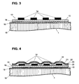
- FIG. 4 is also in a sectional drawing of the arrangement FIG. 3 represented, wherein the strain gauge 13 is still provided on its upper side with a protective layer 20 against moisture penetration.
- This protective layer 20 consists of an inorganic material, and may be formed inhomogeneous over its layer thickness. In a preferred embodiment, it consists of several layers of silicon nitride alternating with silicon oxide, wherein the thickness of the individual layers is between 50 and 200 nanometers.
- the silicon nitride layers 22 serve as barrier layers
- the silicon oxide layers 23 are intended as intermediate layers to cover micropores and microcracks of the barrier layer.
- the multi-layer 20 is a lining layer 21 of a polymer, for example, an acrylate or methacrylate polymer layer or an inorganic-organic hybrid polymer layer, preferably one that corresponds to the adhesive layer 16, underlays.
- a layer 21 smoothes the surface of the strain gauge 13, in particular in the region of the edges, for example, those of the resistance path 14, whereby their edge steepness is reduced.
- irregularities in the surface or even imperfections or dirt particles, be it on the resistance track 14 or the carrier 15 are compensated in a compensatory manner.
- the ausbnende polymer layer 21 reduces the likelihood of the occurrence or adhesion of micropores or hairline cracks in an applied inorganic protective layer 20. As a result, the formation of a poorly dispersed multilayer inorganic protective layer 20 to be applied to the expanding layer 21 is promoted.
- the protective coating can now already be present on the strain gauges 13 to be applied or applied to the strain gauges 13 connected to the deformation body 1 by means of the adhesive layer 16.
- a portion of the protective layer 20 and the underlying ausbnenden polymer layer 21 extend beyond the strain gauge 13 and cover at least a portion of the deformation body 1, in particular the adjacent to the strain gauge 13 areas of the deformation body 1.
- the ingress of moisture in the carrier 15 further reduced.
- the adhesive is present as a solution of the precondensed inorganic components and the organic components, preferably reactive organic groups, in a conventional lacquer solvent.
- the viscosity of the adhesive can be adapted as required to the chosen method of application, for example brushing, spinning, spraying, rolling or pad printing.
- the preferred method for applying a strain gauge 13 to the deformation body 1 of a load cell is to apply an inorganic-organic hybrid polymer in dissolved form by means of pad printing on the deformation body and then settle the strain gauge 13 on the surface provided with the solution and lightly pressed.
- the adhesive layer 16 is cured by crosslinking.
- the curing temperature depends on the choice of the components of the inorganic-organic hybrid polymer and is tuned for the smallest possible increase in the viscoelasticity of the deformation body with the duration of the action of the elevated temperature, which may be between one and three hours. It should be mentioned at this point that the viscoelasticity of aluminum can already be reduced by 50% with a reduction of the curing temperature from 150 ° C. to 100 ° C.
- the tampon printing process provides, by means of an elastically deformable pad, the tampon, the inorganic-organic hybrid polymer in dissolved form - the adhesive - from a plate provided with an etched depression record, the cliché, and on the deformation body directly in the place to be fastened Strain gauge to deposit.
- the shape of the adhesive is maintained during application and it is a uniform adhesive layer 16 is generated.
- the force measuring cell provided with a strain gauge which was applied by means of an adhesive layer according to the invention, has been described and illustrated in a preferred embodiment.
- the material for the beam of the strain gauge is not limited to polyimide.
- Other polymers such as epoxies, phenolic resins, melamines and ketones for strain gauges used in weighing technology can also be used.
- the material for the adhesive layer is to be used. This relates in particular to the variation of the polymeric component of the inorganic-organic hybrid polymer.
Claims (9)
- Cellule de mesure de force comprenant un corps de déformation (1) et au moins une jauge de contrainte (13) appliquée sur le corps de déformation (1) au moyen d'une couche adhésive (16), laquelle présente une bande de résistance (14) électrique, sensible à la dilatation et appliquée sur un support (15) polymère, caractérisée en ce que la couche adhésive (16) est à base d'un polymère hybride inorganique et organique et en ce que la au moins une jauge de contrainte (13) est dotée d'une couche de protection (20) contre la pénétration d'humidité, en dessous de laquelle est posée une couche (21) égalisatrice, qui est à base d'un polymère ou d'un polymère hybride inorganique et organique, la couche de protection (20) étant réalisée sous forme de couche multicouches à base de couches de barrière et de couches intermédiaires, les couches de barrière étant des matériaux inorganiques et les couches intermédiaires des polymères ou des matériaux inorganiques.
- Cellule de mesure de force selon la revendication 1, caractérisée en ce que la couche multicouches conçue comme couche de protection (20) se compose d'une succession alternative d'une couche de barrière (22) à base de nitrure de silicium et d'une couche intermédiaire (23) à base d'oxyde de silicium.
- Cellule de mesure de force selon la revendication 1 ou 2, caractérisée en ce que le corps de déformation (1) est fabriqué en aluminium, le corps de déformation (1) comprenant sur sa surface une couche d'oxyde d'aluminium (19), laquelle est renforcée dans son épaisseur par rapport à une couche d'oxyde naturelle en raison d'un traitement chimique, électrochimique ou thermique et/ou présente une porosité élevée, la liaison avec la couche adhésive (16) étant renforcée par un ancrage mécanique de la couche adhésive (16) dans la couche d'oxyde d'aluminium (19).
- Procédé pour la fixation d'une jauge de contrainte (13) sur un corps de déformation (1) d'une cellule de mesure de force, caractérisé en ce qu'une masse adhésive, qui se compose d'un polymère hybride inorganique et organique dans une forme dissoute, est appliquée sur le corps de déformation (1) pour générer une couche adhésive (16), la jauge de contrainte (13) est appliquée sur la masse adhésive et ensuite la couche adhésive (16) est durcie à une température comprise entre 80°C et 130°C, le corps de déformation (1) avec la jauge de contrainte (13) étant exposé pendant une durée comprise entre une demi-heure et trois heures à la température élevée et en ce que la au moins une jauge de contrainte (13) est dotée d'un revêtement de protection contre la pénétration d'humidité, lequel présente une couche (21) égalisatrice, qui est à base d'un polymère ou d'un polymère hybride inorganique et organique, est appliquée directement sur la jauge de contrainte et présente une couche de protection (20) qui est conçue sous forme de couche multicouches constituée de couches de barrière et de couches intermédiaires, les couches de barrière étant des matériaux inorganiques et les couches intermédiaires des polymères ou des matériaux inorganiques.
- Procédé selon la revendication 4, caractérisé en ce que la jauge de contrainte (13) est sollicité pendant le durcissement avec une pression comprise entre 100 kN/m2 et 1000 kN/m2.
- Procédé selon la revendication 4 ou 5 pour un corps de déformation (1) en aluminium, caractérisé en ce que, pour l'agrandissement de la couche d'oxyde d'aluminium (19) de sa surface, ce corps est réchauffé à une température comprise 40°C et 100°C avant l'application de la masse adhésive pour générer la couche adhésive (16) dans une atmosphère d'oxygène.
- Procédé selon la revendication 4 ou 5 pour un corps de déformation (1) en aluminium, caractérisé en ce, pour agrandir la couche d'oxyde d'aluminium (19) de sa surface, ce corps est soumis à un traitement chimique ou électrochimique avant l'application de la masse adhésive pour générer la couche adhésive (16).
- Procédé selon l'une quelconque des revendications 4 à 7, caractérisé en ce que l'application de la masse adhésive s'effectue au moyen d'un procédé d'impression par tampon pour générer la couche adhésive (16).
- Procédé selon l'une quelconque des revendications 4 à 8, caractérisé en ce que le revêtement de protection est appliqué sur une jauge de contrainte (13) déjà collée sur un corps de déformation (1).
Priority Applications (6)
| Application Number | Priority Date | Filing Date | Title |
|---|---|---|---|
| DE502004010000T DE502004010000D1 (de) | 2004-01-27 | 2004-01-27 | Kraftmesszelle mit Dehnmessstreifen mit Klebeschicht aus anorganisch-organischem Hybrid-Polymer (ORMOCER) |
| EP04075198A EP1560010B1 (fr) | 2004-01-27 | 2004-01-27 | Cellule de mesure de force avec jauge de contrainte avec couche d'adhésif de polymer hybride inorganique-organique (ORMOCER) |
| AT04075198T ATE441843T1 (de) | 2004-01-27 | 2004-01-27 | Kraftmesszelle mit dehnmessstreifen mit klebeschicht aus anorganisch-organischem hybrid- polymer (ormocer) |
| JP2005007547A JP2005214969A (ja) | 2004-01-27 | 2005-01-14 | 力計測セルの変形可能な本体へのひずみゲージの接着技術 |
| CNB200510005766XA CN100538293C (zh) | 2004-01-27 | 2005-01-25 | 应变片与测力元件的变形体的粘结 |
| US11/043,161 US7243558B2 (en) | 2004-01-27 | 2005-01-27 | Bonding of strain gauges to the deformable body of a force-measuring cell |
Applications Claiming Priority (1)
| Application Number | Priority Date | Filing Date | Title |
|---|---|---|---|
| EP04075198A EP1560010B1 (fr) | 2004-01-27 | 2004-01-27 | Cellule de mesure de force avec jauge de contrainte avec couche d'adhésif de polymer hybride inorganique-organique (ORMOCER) |
Publications (2)
| Publication Number | Publication Date |
|---|---|
| EP1560010A1 EP1560010A1 (fr) | 2005-08-03 |
| EP1560010B1 true EP1560010B1 (fr) | 2009-09-02 |
Family
ID=34639445
Family Applications (1)
| Application Number | Title | Priority Date | Filing Date |
|---|---|---|---|
| EP04075198A Expired - Lifetime EP1560010B1 (fr) | 2004-01-27 | 2004-01-27 | Cellule de mesure de force avec jauge de contrainte avec couche d'adhésif de polymer hybride inorganique-organique (ORMOCER) |
Country Status (6)
| Country | Link |
|---|---|
| US (1) | US7243558B2 (fr) |
| EP (1) | EP1560010B1 (fr) |
| JP (1) | JP2005214969A (fr) |
| CN (1) | CN100538293C (fr) |
| AT (1) | ATE441843T1 (fr) |
| DE (1) | DE502004010000D1 (fr) |
Cited By (1)
| Publication number | Priority date | Publication date | Assignee | Title |
|---|---|---|---|---|
| US20220341790A1 (en) * | 2019-09-05 | 2022-10-27 | Minebea Mitsumi Inc. | Sensor module and strain detecting device |
Families Citing this family (32)
| Publication number | Priority date | Publication date | Assignee | Title |
|---|---|---|---|---|
| CN101309638A (zh) | 2005-09-06 | 2008-11-19 | 神经系统检测公司 | 一次性、多用途的心血管自主神经病变的检测装置 |
| DE102006012831A1 (de) | 2006-03-21 | 2007-10-04 | Hottinger Baldwin Messtechnik Gmbh | Dehnungsmessstreifen und Messgrößenaufnehmer mit mindestens einem Dehnungsmessstreifen |
| JP2008002870A (ja) * | 2006-06-21 | 2008-01-10 | Ishida Co Ltd | ロードセル、およびその製造方法 |
| JP2011513736A (ja) * | 2008-02-27 | 2011-04-28 | メジャメント スペシャリティーズ, インコーポレイテッド | ビームおよびダイヤフラムを使用する低圧トランスデューサ |
| FR2937725B1 (fr) * | 2008-10-24 | 2011-01-21 | Snecma | Procede pour installer et proteger un capteur sur un substrat |
| FR2944865B1 (fr) * | 2009-04-27 | 2011-06-24 | Commissariat Energie Atomique | Capteur de contrainte et son procede de realisation. |
| DE102010012670B4 (de) * | 2010-03-24 | 2020-09-03 | Soehnle Industrial Solutions Gmbh | Gabelstapler mit einer Vorrichtung zur Erfassung einer Gewichtsbelastung |
| CN102221430B (zh) * | 2010-04-13 | 2013-07-10 | 精量电子(深圳)有限公司 | 一种微熔粘接应变片的方法 |
| JP5893857B2 (ja) * | 2011-06-24 | 2016-03-23 | 株式会社ミツトヨ | スケールの目盛保護構造 |
| DE102011053505A1 (de) * | 2011-09-12 | 2013-03-14 | Scambia Holdings Cyprus Ltd. | Trägereinheit |
| CN102645156B (zh) * | 2012-04-25 | 2014-11-12 | 中航电测仪器股份有限公司 | 一种提高酚醛基底电阻应变计质量的方法 |
| WO2014153094A1 (fr) * | 2013-03-14 | 2014-09-25 | Santi Larry D | Balance de chariot à fourche, sa cellule de charge et procédé de mesure d'une charge de chariot à fourche |
| FR3023909B1 (fr) * | 2014-07-17 | 2020-11-20 | Centre Techn Ind Mecanique | Procede de realisation d'un capteur d'efforts et installation de mise en œuvre |
| DE102014013812A1 (de) * | 2014-09-23 | 2016-03-24 | Westfalia-Automotive Gmbh | Anhängekupplung mit einem Sensor |
| JP2016125977A (ja) * | 2015-01-08 | 2016-07-11 | 昭和電工株式会社 | 歪ゲージ接着方法 |
| JP2017067764A (ja) * | 2015-09-29 | 2017-04-06 | ミネベアミツミ株式会社 | ひずみゲージ、荷重センサ、及びひずみゲージの製造方法 |
| CN105803381B (zh) * | 2016-03-30 | 2018-04-13 | 中国人民解放军装甲兵工程学院 | 一种基于应变片安装的高温应变喷涂方法 |
| DE102016108541A1 (de) * | 2016-05-09 | 2017-11-09 | Bosal Nederland B.V. | Vorrichtung zum Ziehen eines Anhängers und/oder Halten einer Lastenträgereinheit |
| CN108120369A (zh) * | 2016-11-28 | 2018-06-05 | 梅特勒-托利多(常州)精密仪器有限公司 | 固定应变片的方法及装置 |
| JP6793103B2 (ja) | 2017-09-29 | 2020-12-02 | ミネベアミツミ株式会社 | ひずみゲージ |
| JP2019066453A (ja) | 2017-09-29 | 2019-04-25 | ミネベアミツミ株式会社 | ひずみゲージ |
| JP2019066312A (ja) | 2017-09-29 | 2019-04-25 | ミネベアミツミ株式会社 | ひずみゲージ |
| JP2019066454A (ja) | 2017-09-29 | 2019-04-25 | ミネベアミツミ株式会社 | ひずみゲージ、センサモジュール |
| JP2019082424A (ja) * | 2017-10-31 | 2019-05-30 | ミネベアミツミ株式会社 | ひずみゲージ |
| JP2019113411A (ja) | 2017-12-22 | 2019-07-11 | ミネベアミツミ株式会社 | ひずみゲージ、センサモジュール |
| JP2019184344A (ja) | 2018-04-05 | 2019-10-24 | ミネベアミツミ株式会社 | ひずみゲージ及びその製造方法 |
| EP3617683A1 (fr) * | 2018-08-31 | 2020-03-04 | Mettler Toledo (Changzhou) Precision Instrument Ltd. | Procédé d'isolation d'un détecteur de contrainte contre la pénétration d'humidité |
| JPWO2020085247A1 (ja) | 2018-10-23 | 2021-09-16 | ミネベアミツミ株式会社 | アクセルペダル、ステアリング、ドア、ドア開閉システム |
| CN112284581B (zh) * | 2020-10-27 | 2022-04-15 | 湖北长江新型显示产业创新中心有限公司 | 一种传感器、显示面板及电子设备 |
| FR3116339B1 (fr) * | 2020-11-16 | 2022-11-11 | Commissariat Energie Atomique | Jauge d’extensométrie inorganique |
| CN113532259A (zh) * | 2021-07-23 | 2021-10-22 | 中国航发贵阳发动机设计研究所 | 一种m-610胶粘剂粘贴应变计工艺 |
| US11874192B2 (en) * | 2021-08-04 | 2024-01-16 | Vishay Advanced Technologies Ltd. | Elongate force sensor assembly with throughgoing bore |
Citations (3)
| Publication number | Priority date | Publication date | Assignee | Title |
|---|---|---|---|---|
| US5631622A (en) * | 1994-02-15 | 1997-05-20 | Hottinger Baldwin Messtechnik Gmbh | Strain gage and measuring transducer and method of producing the same |
| US6283578B1 (en) * | 1996-06-28 | 2001-09-04 | Pelikan Produktions Ag | Hydrophobic coating for ink jet printing heads |
| EP1308705A1 (fr) * | 2001-10-27 | 2003-05-07 | Robert Bosch Gmbh | Procédé de fabrication d'un element capteur et son utilisation |
Family Cites Families (19)
| Publication number | Priority date | Publication date | Assignee | Title |
|---|---|---|---|---|
| US3935636A (en) * | 1974-03-29 | 1976-02-03 | Tyco Laboratories, Inc. | Method of making a pressure transducer |
| GB2051819A (en) * | 1979-06-29 | 1981-01-21 | Bofors America | Epoxy resin adhesive composition |
| GB8303555D0 (en) * | 1983-02-09 | 1983-03-16 | Strain Measurement Dev Ltd | Strain gauges |
| CH677988A5 (fr) * | 1986-07-30 | 1991-07-15 | Actron Entwicklungs Ag | |
| JP2539639B2 (ja) * | 1987-10-28 | 1996-10-02 | 株式会社共和電業 | 高温用ひずみゲ―ジおよびその添着構造 |
| JPH01169303A (ja) * | 1987-12-25 | 1989-07-04 | Sumitomo Heavy Ind Ltd | 歪検出器の製作方法 |
| JP2651556B2 (ja) * | 1992-12-11 | 1997-09-10 | 株式会社 寺岡精工 | ロードセル及びその製造方法 |
| JPH06281511A (ja) * | 1993-03-26 | 1994-10-07 | Tokyo Electric Co Ltd | 歪センサ |
| DE4320666A1 (de) * | 1993-06-22 | 1995-01-05 | Hottinger Messtechnik Baldwin | Dehnungsmeßstreifen |
| JPH0735628A (ja) * | 1993-07-16 | 1995-02-07 | Kyowa Electron Instr Co Ltd | ひずみゲージ添着個所被覆構造およびその被覆方法 |
| JPH0744039A (ja) * | 1993-07-27 | 1995-02-14 | Toshiba Lighting & Technol Corp | 平面ヒータ |
| JPH098326A (ja) * | 1995-06-15 | 1997-01-10 | Matsushita Electric Works Ltd | 半導体圧力センサ |
| JP3520652B2 (ja) * | 1996-02-08 | 2004-04-19 | 株式会社デンソー | 半導体力センサ |
| WO1999042799A1 (fr) * | 1998-02-18 | 1999-08-26 | Honeywell Data Instruments, Inc. | Jauge de contrainte a isolation electrique |
| JP3336992B2 (ja) * | 1999-04-09 | 2002-10-21 | 株式会社寺岡精工 | ロードセル |
| JP3613086B2 (ja) * | 1999-08-31 | 2005-01-26 | 荒川化学工業株式会社 | 有機無機ハイブリッドポリウレタン用組成物および有機無機ハイブリッドポリウレタン |
| JP4635312B2 (ja) * | 2000-09-21 | 2011-02-23 | 日立化成工業株式会社 | 接着剤組成物、回路接続材料、回路接続用接着剤組成物、接続体及び半導体装置 |
| JP2002139389A (ja) * | 2000-10-30 | 2002-05-17 | Nagano Keiki Co Ltd | 荷重測定用センシング素子 |
| JP2002365146A (ja) * | 2001-06-12 | 2002-12-18 | Ishida Co Ltd | ロードセル |
-
2004
- 2004-01-27 EP EP04075198A patent/EP1560010B1/fr not_active Expired - Lifetime
- 2004-01-27 AT AT04075198T patent/ATE441843T1/de not_active IP Right Cessation
- 2004-01-27 DE DE502004010000T patent/DE502004010000D1/de not_active Expired - Lifetime
-
2005
- 2005-01-14 JP JP2005007547A patent/JP2005214969A/ja active Pending
- 2005-01-25 CN CNB200510005766XA patent/CN100538293C/zh not_active Expired - Fee Related
- 2005-01-27 US US11/043,161 patent/US7243558B2/en active Active
Patent Citations (3)
| Publication number | Priority date | Publication date | Assignee | Title |
|---|---|---|---|---|
| US5631622A (en) * | 1994-02-15 | 1997-05-20 | Hottinger Baldwin Messtechnik Gmbh | Strain gage and measuring transducer and method of producing the same |
| US6283578B1 (en) * | 1996-06-28 | 2001-09-04 | Pelikan Produktions Ag | Hydrophobic coating for ink jet printing heads |
| EP1308705A1 (fr) * | 2001-10-27 | 2003-05-07 | Robert Bosch Gmbh | Procédé de fabrication d'un element capteur et son utilisation |
Cited By (1)
| Publication number | Priority date | Publication date | Assignee | Title |
|---|---|---|---|---|
| US20220341790A1 (en) * | 2019-09-05 | 2022-10-27 | Minebea Mitsumi Inc. | Sensor module and strain detecting device |
Also Published As
| Publication number | Publication date |
|---|---|
| ATE441843T1 (de) | 2009-09-15 |
| EP1560010A1 (fr) | 2005-08-03 |
| JP2005214969A (ja) | 2005-08-11 |
| CN100538293C (zh) | 2009-09-09 |
| CN1648625A (zh) | 2005-08-03 |
| DE502004010000D1 (de) | 2009-10-15 |
| US20050160837A1 (en) | 2005-07-28 |
| US7243558B2 (en) | 2007-07-17 |
Similar Documents
| Publication | Publication Date | Title |
|---|---|---|
| EP1560010B1 (fr) | Cellule de mesure de force avec jauge de contrainte avec couche d'adhésif de polymer hybride inorganique-organique (ORMOCER) | |
| EP1560011B1 (fr) | Jauge de contrainte avec protection contre l'humidité au moyen d'une couche inorganique inhomogène sur une couche polymère d'égalisation (ORMOCER) et un arrangement de fentes | |
| EP2126511B1 (fr) | Jauge optique d'allongement | |
| EP0596293B1 (fr) | Jauge d'allongement et transducteur comportant une telle jauge | |
| DE69727793T2 (de) | Verbundmaterial aus Silikongummi und Polyesterharz | |
| EP1999445B1 (fr) | Jauge de contrainte et enregistreur de grandeur mesuree comprenant au moins une jauge de contrainte | |
| EP2881249B1 (fr) | Composite de polymère de fibres naturelles et matériau de base léger et écologique pour habitacles d'automobiles | |
| DE102018118116A1 (de) | Verfahren zur Herstellung eines elektrisch leitfähigen Substrats, einer elektronischen Vorrichtung und einer Anzeigevorrichtung | |
| EP0096156B1 (fr) | Procédé pour couvrir des structures physiques sensibles d'une façon quasi-hermétique et avec une influence limitée, en particulier pour jauges de contrainte | |
| DE3724290A1 (de) | Elektrode fuer piezoelektrische composites | |
| DE102016120906B4 (de) | Eingabegerät mit einem Array von Kraftsensoren und partiell gehärteter Zwischenschicht | |
| DE102010021914A1 (de) | Sensorvorrichtung für physikalische Größe und Herstellungsverfahren derselben | |
| DE102006023724A1 (de) | Messzellenanordnung für einen Drucksensor mit Kraftmesselement aus Glas | |
| DE102010054970B4 (de) | Vorrichtung zum Wandeln einer Dehnung und/oder Stauchung in ein elektrisches Signal, insbesondere Dehnungsmessfolie | |
| DE4312788C2 (de) | Feuchtesensor | |
| EP1263060A2 (fr) | Méthode de fabrication d'un élément plat multicouche et élément correspondant | |
| DE102010008397A1 (de) | Sensorsystem zur Bestimmung der Ermüdung an metallischen Bauteilen | |
| EP1308705A1 (fr) | Procédé de fabrication d'un element capteur et son utilisation | |
| EP1200986A1 (fr) | Structure couche de passivation | |
| DE102017218363A1 (de) | Oberflächenstrukturierte polymerkörper und verfahren zu ihrer herstellung | |
| DE102011119349A1 (de) | Verfahren zur Herstellung eines Dünnschichtsensorelements | |
| DE102013207779A1 (de) | Multischichtaufbau mit alternierenden leitenden und nicht leitenden Schichten | |
| DE102017000455A1 (de) | Verfahren und System zur Erkennung von Deformationen oder Deformationsänderungen an beschichteten Bauteilen | |
| DE19506863A1 (de) | pH-Sensor in Dickschichttechnik und Verfahren zu seiner Herstellung | |
| DE10003009B4 (de) | Messvorrichtung zur Charakterisierung von mechanischen Spannungszuständen in flächenhaften Materialien |
Legal Events
| Date | Code | Title | Description |
|---|---|---|---|
| PUAI | Public reference made under article 153(3) epc to a published international application that has entered the european phase |
Free format text: ORIGINAL CODE: 0009012 |
|
| AK | Designated contracting states |
Kind code of ref document: A1 Designated state(s): AT BE BG CH CY CZ DE DK EE ES FI FR GB GR HU IE IT LI LU MC NL PT RO SE SI SK TR |
|
| AX | Request for extension of the european patent |
Extension state: AL LT LV MK |
|
| 17P | Request for examination filed |
Effective date: 20060202 |
|
| AKX | Designation fees paid |
Designated state(s): AT BE BG CH CY CZ DE DK EE ES FI FR GB GR HU IE IT LI LU MC NL PT RO SE SI SK TR |
|
| RAP1 | Party data changed (applicant data changed or rights of an application transferred) |
Owner name: METTLER-TOLEDO AG |
|
| 17Q | First examination report despatched |
Effective date: 20061108 |
|
| 17Q | First examination report despatched |
Effective date: 20061108 |
|
| GRAP | Despatch of communication of intention to grant a patent |
Free format text: ORIGINAL CODE: EPIDOSNIGR1 |
|
| GRAS | Grant fee paid |
Free format text: ORIGINAL CODE: EPIDOSNIGR3 |
|
| GRAA | (expected) grant |
Free format text: ORIGINAL CODE: 0009210 |
|
| AK | Designated contracting states |
Kind code of ref document: B1 Designated state(s): AT BE BG CH CY CZ DE DK EE ES FI FR GB GR HU IE IT LI LU MC NL PT RO SE SI SK TR |
|
| REG | Reference to a national code |
Ref country code: CH Ref legal event code: EP |
|
| REG | Reference to a national code |
Ref country code: IE Ref legal event code: FG4D Free format text: LANGUAGE OF EP DOCUMENT: GERMAN |
|
| REF | Corresponds to: |
Ref document number: 502004010000 Country of ref document: DE Date of ref document: 20091015 Kind code of ref document: P |
|
| PG25 | Lapsed in a contracting state [announced via postgrant information from national office to epo] |
Ref country code: SE Free format text: LAPSE BECAUSE OF FAILURE TO SUBMIT A TRANSLATION OF THE DESCRIPTION OR TO PAY THE FEE WITHIN THE PRESCRIBED TIME-LIMIT Effective date: 20090902 Ref country code: FI Free format text: LAPSE BECAUSE OF FAILURE TO SUBMIT A TRANSLATION OF THE DESCRIPTION OR TO PAY THE FEE WITHIN THE PRESCRIBED TIME-LIMIT Effective date: 20090902 |
|
| NLV1 | Nl: lapsed or annulled due to failure to fulfill the requirements of art. 29p and 29m of the patents act | ||
| PG25 | Lapsed in a contracting state [announced via postgrant information from national office to epo] |
Ref country code: NL Free format text: LAPSE BECAUSE OF FAILURE TO SUBMIT A TRANSLATION OF THE DESCRIPTION OR TO PAY THE FEE WITHIN THE PRESCRIBED TIME-LIMIT Effective date: 20090902 Ref country code: SI Free format text: LAPSE BECAUSE OF FAILURE TO SUBMIT A TRANSLATION OF THE DESCRIPTION OR TO PAY THE FEE WITHIN THE PRESCRIBED TIME-LIMIT Effective date: 20090902 |
|
| PG25 | Lapsed in a contracting state [announced via postgrant information from national office to epo] |
Ref country code: CY Free format text: LAPSE BECAUSE OF FAILURE TO SUBMIT A TRANSLATION OF THE DESCRIPTION OR TO PAY THE FEE WITHIN THE PRESCRIBED TIME-LIMIT Effective date: 20090902 |
|
| REG | Reference to a national code |
Ref country code: IE Ref legal event code: FD4D |
|
| PG25 | Lapsed in a contracting state [announced via postgrant information from national office to epo] |
Ref country code: CZ Free format text: LAPSE BECAUSE OF FAILURE TO SUBMIT A TRANSLATION OF THE DESCRIPTION OR TO PAY THE FEE WITHIN THE PRESCRIBED TIME-LIMIT Effective date: 20090902 Ref country code: IE Free format text: LAPSE BECAUSE OF FAILURE TO SUBMIT A TRANSLATION OF THE DESCRIPTION OR TO PAY THE FEE WITHIN THE PRESCRIBED TIME-LIMIT Effective date: 20090902 Ref country code: PT Free format text: LAPSE BECAUSE OF FAILURE TO SUBMIT A TRANSLATION OF THE DESCRIPTION OR TO PAY THE FEE WITHIN THE PRESCRIBED TIME-LIMIT Effective date: 20100104 Ref country code: RO Free format text: LAPSE BECAUSE OF FAILURE TO SUBMIT A TRANSLATION OF THE DESCRIPTION OR TO PAY THE FEE WITHIN THE PRESCRIBED TIME-LIMIT Effective date: 20090902 Ref country code: EE Free format text: LAPSE BECAUSE OF FAILURE TO SUBMIT A TRANSLATION OF THE DESCRIPTION OR TO PAY THE FEE WITHIN THE PRESCRIBED TIME-LIMIT Effective date: 20090902 Ref country code: ES Free format text: LAPSE BECAUSE OF FAILURE TO SUBMIT A TRANSLATION OF THE DESCRIPTION OR TO PAY THE FEE WITHIN THE PRESCRIBED TIME-LIMIT Effective date: 20091213 |
|
| PG25 | Lapsed in a contracting state [announced via postgrant information from national office to epo] |
Ref country code: SK Free format text: LAPSE BECAUSE OF FAILURE TO SUBMIT A TRANSLATION OF THE DESCRIPTION OR TO PAY THE FEE WITHIN THE PRESCRIBED TIME-LIMIT Effective date: 20090902 |
|
| PLBE | No opposition filed within time limit |
Free format text: ORIGINAL CODE: 0009261 |
|
| STAA | Information on the status of an ep patent application or granted ep patent |
Free format text: STATUS: NO OPPOSITION FILED WITHIN TIME LIMIT |
|
| PG25 | Lapsed in a contracting state [announced via postgrant information from national office to epo] |
Ref country code: DK Free format text: LAPSE BECAUSE OF FAILURE TO SUBMIT A TRANSLATION OF THE DESCRIPTION OR TO PAY THE FEE WITHIN THE PRESCRIBED TIME-LIMIT Effective date: 20090902 |
|
| BERE | Be: lapsed |
Owner name: METTLER-TOLEDO A.G. Effective date: 20100131 |
|
| 26N | No opposition filed |
Effective date: 20100603 |
|
| PG25 | Lapsed in a contracting state [announced via postgrant information from national office to epo] |
Ref country code: MC Free format text: LAPSE BECAUSE OF NON-PAYMENT OF DUE FEES Effective date: 20100131 |
|
| PG25 | Lapsed in a contracting state [announced via postgrant information from national office to epo] |
Ref country code: GR Free format text: LAPSE BECAUSE OF FAILURE TO SUBMIT A TRANSLATION OF THE DESCRIPTION OR TO PAY THE FEE WITHIN THE PRESCRIBED TIME-LIMIT Effective date: 20091203 |
|
| PGFP | Annual fee paid to national office [announced via postgrant information from national office to epo] |
Ref country code: FR Payment date: 20101221 Year of fee payment: 8 |
|
| PG25 | Lapsed in a contracting state [announced via postgrant information from national office to epo] |
Ref country code: BE Free format text: LAPSE BECAUSE OF NON-PAYMENT OF DUE FEES Effective date: 20100131 |
|
| PG25 | Lapsed in a contracting state [announced via postgrant information from national office to epo] |
Ref country code: IT Free format text: LAPSE BECAUSE OF FAILURE TO SUBMIT A TRANSLATION OF THE DESCRIPTION OR TO PAY THE FEE WITHIN THE PRESCRIBED TIME-LIMIT Effective date: 20090902 |
|
| PGFP | Annual fee paid to national office [announced via postgrant information from national office to epo] |
Ref country code: GB Payment date: 20101215 Year of fee payment: 8 |
|
| PG25 | Lapsed in a contracting state [announced via postgrant information from national office to epo] |
Ref country code: AT Free format text: LAPSE BECAUSE OF NON-PAYMENT OF DUE FEES Effective date: 20100127 |
|
| PGFP | Annual fee paid to national office [announced via postgrant information from national office to epo] |
Ref country code: CH Payment date: 20110103 Year of fee payment: 8 |
|
| REG | Reference to a national code |
Ref country code: CH Ref legal event code: PL |
|
| GBPC | Gb: european patent ceased through non-payment of renewal fee |
Effective date: 20120127 |
|
| PG25 | Lapsed in a contracting state [announced via postgrant information from national office to epo] |
Ref country code: BG Free format text: LAPSE BECAUSE OF FAILURE TO SUBMIT A TRANSLATION OF THE DESCRIPTION OR TO PAY THE FEE WITHIN THE PRESCRIBED TIME-LIMIT Effective date: 20090902 Ref country code: HU Free format text: LAPSE BECAUSE OF FAILURE TO SUBMIT A TRANSLATION OF THE DESCRIPTION OR TO PAY THE FEE WITHIN THE PRESCRIBED TIME-LIMIT Effective date: 20100303 Ref country code: LU Free format text: LAPSE BECAUSE OF NON-PAYMENT OF DUE FEES Effective date: 20100127 |
|
| REG | Reference to a national code |
Ref country code: FR Ref legal event code: ST Effective date: 20120928 |
|
| PG25 | Lapsed in a contracting state [announced via postgrant information from national office to epo] |
Ref country code: TR Free format text: LAPSE BECAUSE OF FAILURE TO SUBMIT A TRANSLATION OF THE DESCRIPTION OR TO PAY THE FEE WITHIN THE PRESCRIBED TIME-LIMIT Effective date: 20090902 Ref country code: GB Free format text: LAPSE BECAUSE OF NON-PAYMENT OF DUE FEES Effective date: 20120127 Ref country code: CH Free format text: LAPSE BECAUSE OF NON-PAYMENT OF DUE FEES Effective date: 20120131 Ref country code: LI Free format text: LAPSE BECAUSE OF NON-PAYMENT OF DUE FEES Effective date: 20120131 |
|
| PG25 | Lapsed in a contracting state [announced via postgrant information from national office to epo] |
Ref country code: FR Free format text: LAPSE BECAUSE OF NON-PAYMENT OF DUE FEES Effective date: 20120131 |
|
| PGFP | Annual fee paid to national office [announced via postgrant information from national office to epo] |
Ref country code: DE Payment date: 20160127 Year of fee payment: 13 |
|
| REG | Reference to a national code |
Ref country code: DE Ref legal event code: R119 Ref document number: 502004010000 Country of ref document: DE |
|
| PG25 | Lapsed in a contracting state [announced via postgrant information from national office to epo] |
Ref country code: DE Free format text: LAPSE BECAUSE OF NON-PAYMENT OF DUE FEES Effective date: 20170801 |