EP1557634B1 - Vorrichtung zur Halterung einer Waffenstation - Google Patents
Vorrichtung zur Halterung einer Waffenstation Download PDFInfo
- Publication number
- EP1557634B1 EP1557634B1 EP05000907A EP05000907A EP1557634B1 EP 1557634 B1 EP1557634 B1 EP 1557634B1 EP 05000907 A EP05000907 A EP 05000907A EP 05000907 A EP05000907 A EP 05000907A EP 1557634 B1 EP1557634 B1 EP 1557634B1
- Authority
- EP
- European Patent Office
- Prior art keywords
- weapon
- weapon station
- sidepieces
- station
- bearing
- Prior art date
- Legal status (The legal status is an assumption and is not a legal conclusion. Google has not performed a legal analysis and makes no representation as to the accuracy of the status listed.)
- Revoked
Links
- 230000003287 optical effect Effects 0.000 claims description 4
- 239000004429 Calibre Substances 0.000 claims 1
- 238000009434 installation Methods 0.000 abstract description 3
- 230000006978 adaptation Effects 0.000 description 1
- 238000010276 construction Methods 0.000 description 1
- 238000013016 damping Methods 0.000 description 1
- 230000001419 dependent effect Effects 0.000 description 1
- 244000144992 flock Species 0.000 description 1
- 238000001931 thermography Methods 0.000 description 1
- 238000005303 weighing Methods 0.000 description 1
Images


Classifications
-
- F—MECHANICAL ENGINEERING; LIGHTING; HEATING; WEAPONS; BLASTING
- F41—WEAPONS
- F41A—FUNCTIONAL FEATURES OR DETAILS COMMON TO BOTH SMALLARMS AND ORDNANCE, e.g. CANNONS; MOUNTINGS FOR SMALLARMS OR ORDNANCE
- F41A23/00—Gun mountings, e.g. on vehicles; Disposition of guns on vehicles
- F41A23/34—Gun mountings, e.g. on vehicles; Disposition of guns on vehicles on wheeled or endless-track vehicles
-
- F—MECHANICAL ENGINEERING; LIGHTING; HEATING; WEAPONS; BLASTING
- F41—WEAPONS
- F41A—FUNCTIONAL FEATURES OR DETAILS COMMON TO BOTH SMALLARMS AND ORDNANCE, e.g. CANNONS; MOUNTINGS FOR SMALLARMS OR ORDNANCE
- F41A23/00—Gun mountings, e.g. on vehicles; Disposition of guns on vehicles
- F41A23/005—Locks for connecting guns to their mountings
-
- F—MECHANICAL ENGINEERING; LIGHTING; HEATING; WEAPONS; BLASTING
- F41—WEAPONS
- F41A—FUNCTIONAL FEATURES OR DETAILS COMMON TO BOTH SMALLARMS AND ORDNANCE, e.g. CANNONS; MOUNTINGS FOR SMALLARMS OR ORDNANCE
- F41A23/00—Gun mountings, e.g. on vehicles; Disposition of guns on vehicles
- F41A23/20—Gun mountings, e.g. on vehicles; Disposition of guns on vehicles for disappearing guns
-
- F—MECHANICAL ENGINEERING; LIGHTING; HEATING; WEAPONS; BLASTING
- F41—WEAPONS
- F41A—FUNCTIONAL FEATURES OR DETAILS COMMON TO BOTH SMALLARMS AND ORDNANCE, e.g. CANNONS; MOUNTINGS FOR SMALLARMS OR ORDNANCE
- F41A23/00—Gun mountings, e.g. on vehicles; Disposition of guns on vehicles
- F41A23/50—Travelling locks; Brakes for holding the gun platform in a fixed position during transport
Definitions
- the invention relates to a device for holding a weapons station for a vehicle.
- the invention relates to an armored and armed vehicle, which consists of the usual parts such as drive motor, gears, wheelsets or track drive, a crew room and a housing that houses all inputs and attachments, and a weapons station, especially with a smaller caliber, or a weapon station containing two weapons.
- a weapon station consists as Freirichtlafette essentially of a ring or platform with side pivot bearing and a weapon carrier. Simple weapon stations are characterized in that they are rotatably mounted on a flange about a vehicle hatch around.
- An armored transport vehicle which proposes to accommodate different weapons on a mount, interpret the arrangement and the distance of the trunnion with the largest caliber and incorporate an adapter device between the trunnion and the weapon mount.
- a secondary weapon With the DE 977 774 C the transport of a secondary weapon is described, which should lie completely under armored protection at rest.
- the auxiliary weapon is attached to a pivot lever which can be pivoted by a hydraulic lifting device from its rest position into the functional position. By pivoting around pegs, the weapon can be leveled. The weapon lies directly in this pin. A weapon with a different caliber can not be installed here.
- a hinged weapon station in which the weapon-carrying part of the weapon station is pivotally mounted directly above the side pivot bearing.
- a support ring locks the weapon position in the upper functional position.
- the pivot axis itself is mounted obliquely in the side pivot bearing, the moving rods are different lengths.
- a weapon with a different caliber can not be installed here.
- an armored transport vehicle with an on-board machine gun is known, which is suspended by trunnion In a carriage, which is mounted on a turntable on the roof of the vehicle pan.
- the flock tower is designed so that different on-board machine guns, especially with different calibers can be arranged with the same position of the trunnions and on the same turntable.
- This project is realized in that a weapon with the largest caliber provided on the trunnions (directly) can be hung, while the associated with the smaller calibers via an adapter device with the trunnions.
- This designed as a weighing trough weapon mount is then hung for the smaller caliber weapons on the trunnion.
- the weapons receptacle is held by means of receptacles adapted to its particular shape.
- a screen is arranged at the front of the cradle trough.
- the object of the invention is to provide a simple device for receiving different weapons in caliber.
- Each weapon can also be mounted individually at the weapon station.
- each weapon When combining two weapons, each weapon is supplied with ammunition on the respective side where the weapon is located. Caliber-dependent ammunition transport belts are used for the respective weapon.
- the weapon station can be closed under armored protection, the hatch of the gun carriage can be ammunitioned from the vehicle interior.
- the ammunition boxes can have a large viewing window, creating a recognizability of existing in the ammunition boxes ammunition is created.
- the movement of the weapon station is done by manual straightening drives in height and side with a translation in the drives.
- the optical view all around (360 °) can be realized by a separate arrangement of the optics with angular mirrors.
- An optic with integrated thermal imaging device can also be used. The subsequent installation of this optics in the weapon station is also possible.
- hinged cheeks are used with a pivot bearing in an advantageous manner, which are used for arm support by means of adaptation of the body of a weapon station.
- An extendable elevation drive which is partially integrated into the hinged cheeks, allows the short-term combat preparation of the weapon station.
- the design of the folding cheeks varies depending on the size and design of the male carriage. The advantages are that the device with folding cheeks and pivot bearings because of the small installation dimensions improves the air loadability and allows a short upgrade time to be ready to fight. The easy handling facilitates the construction.
- Fig. 1 shows the essential details of the pivoting device for a weapon not shown here 1.
- This consists of a pivot bearing 6, which has a U-shaped receptacle and is preferably received by two lateral cheeks 4.
- the cheeks 4 are mounted at the lower end by means of cheek bearing bolts 5 in a cheek bearing 3.
- a side pivot bearing 2 receives the cheek rest 3.
- the side pivot bearing 2 is installed on a vehicle roof (not shown).
- Fig. 2 shows a weapon station W with a weapon 1 in a functional position above or ready for battle.
- the weapon here a light machine gun with a small caliber or other lighter weapon that can be operated by an operator alone, is mounted centrally in the pivot bearing 6 and is rotatable about an axis 6a in the pivot bearing 6. So this weapon can be supplied either from the left or from the right with an ammunition, not shown.
- This is fed from below through the cheek bearing 3 to the outside and from there, for example, in a flexible belt on one of the cheeks 4 to the weapon 1.
- These lateral cheeks 4 receive the pivot bearing 6 and are, as already described, mounted at the lower end by means of the cheek bearing pins 5 in the cheek bearing 3.
- the side pivot bearing 2 takes next to the cheek bearing 3, other parts such as a turntable and angle mirror 8, and is rotatable about a vertical axis 7.
- this weapon station W is shown in perspective.
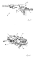
- Fig. 4 In the transport position with the weapon 1, Fig. 4 , the lock between the cheek bearing 3 and cheek 4 is released, so that the cheeks 4 can be pivoted on the cheek bearing pin as a fulcrum and thus the weapon 1 forward. As a result, the weapon 1 comes forward and at the same time down to a lower position.
- Fig. 5 represents this transport position in perspective.
- the invention relates to a folding weapon station W, wherein the two cheeks 4 as support arms and the pivot bearing 6 are folded forward in the sense of pivoting about the axis 6a. This gives a low height of the entire weapon station W. This is the lowest contour in terms of height achieved.
- a vehicle with folding weapon station W can enter an aircraft without much preparation.
- the weapons mounted on the pivot bearing 6 usually do not have to be removed.
- the weapon station is after folding up the cheeks 4 by means of cheek bearing 5 and the locking of the two folding cheeks 4 immediately ready for use again with attached weapon 1, 1a. This makes it possible to establish combat readiness in a very short time.
- the hinged weight is supported and balanced by means of a screw or gas or hydraulic spring or hydraulic damping system, etc. Thus, an abrupt pivoting due to the mass action is prevented and the operation does not require large forces.
- the elevation adjustment (height adjustment) of the weapon 1 or weapons 1, 1a is carried out by a well-knownnaturetantrieb not shown.
- the pivoting of the weapon 1 or weapons 1, 1 a in height is carried out by the pivot bearing. 6
- the circular configuration of the side rotary bearing 2 encloses an inner circular surface in which an opening and closing vehicle hatch for the vehicle crew is housed, which can be opened, removed or laterally swung away.
Landscapes
- Engineering & Computer Science (AREA)
- General Engineering & Computer Science (AREA)
- Aiming, Guidance, Guns With A Light Source, Armor, Camouflage, And Targets (AREA)
- Forklifts And Lifting Vehicles (AREA)
Description
- Die Erfindung betrifft eine Vorrichtung zur Halterung einer Waffenstation für ein Fahrzeug.
- Die Erfindung bezieht sich auf ein gepanzertes und bewaffnetes Fahrzeug, das sich aus den üblichen Teilen wie Antriebsmotor, Getrieben, Radsätzen oder Kettenlaufwerk, einem Besatzungsraum und einem Gehäuse, das alle Ein- und Anbauten aufnimmt, und einer Waffenstation, insbesondere mit einem kleineren Kaliber, oder einer Waffenstation, die zwei Waffen enthält, zusammensetzt. Eine Waffenstation besteht als Freirichtlafette im Wesentlichen aus einem Ring oder Plattform mit Seitendrehlager und einem Waffenträger. Einfache Waffenstationen sind dadurch gekennzeichnet, dass sie auf einem Flanschring drehbar um eine Fahrzeugluke herum angebracht sind.
- Aus der
EP 1 061 323 B1 ist ein gepanzertes Transportfahrzeug bekannt, welches zur Aufnahme unterschiedlicher Waffen auf einer Lafette vorschlägt, die Anordnung und den Abstand der Schildzapfen mit dem größten Kaliber auszulegen und zwischen den Schildzapfen und der Waffenaufnahme eine Adaptionsvorrichtung einzubinden. - Mit der
DE 977 774 C wird der Transport einer Nebenwaffe beschrieben, die in Ruhestellung vollständig unter Panzerschutz liegen soll. Die Nebenwaffe ist an einem Schwenkhebel befestigt, der durch eine hydraulische Hebevorrichtung aus seiner Ruhelage in die Funktionsstellung geschwenkt werden kann. Durch Schwenken um Zapfen kann die Waffe in der Höhe gerichtet werden. Die Waffe liegt dabei direkt in diesen Zapfen. Eine Waffe mit einem anderen Kaliber kann hier nicht eingebaut werden. - In der
EP 1 333 239 A2 wird eine abklappbare Waffenstation offenbart, bei welcher der waffentragende Teil der Waffenstation direkt über dem Seitendrehlager schwenkbar gelagert ist. Ein Abstützring verriegelt die Waffenlage in der oberen Funktionsstellung. Die Schwenkachse selbst ist schräg im Seitendrehlager angebracht, die beweglichen Stäbe sind unterschiedlich lang. Eine Waffe mit einem anderen Kaliber kann hier nicht eingebaut werden. - Mit der WO 03/046467 A1 wird u. a. die Bestückung verschiedener Waffen an einer Lafette publiziert. Jedes Waffensystem arbeitet vom anderen autark, ein gemeinsames Richten in der Höhe erfolgt nicht.
- Aus der
EP 1 061 323 A1 , welche eine vorrichtung gemäβ oberbegriff des Anspruchs 1 offenbart, ist ein gepanzertes Transportfahrzeug mit einer Bordmaschinenwaffe (MW) bekannt, die über Schildzapfen In einer Lafette aufgehängt ist, die über einen Drehkranz auf dem Dach der Fahrzeugwanne gelagert ist. Der Schartenturm Ist dabei so ausgebildet, dass unterschiedliche Bordmaschinenwaffen, insbesondere mit unterschiedlichen Kalibern mit der gleichen Lage der Schildzapfen und auf dem gleichen Drehkranz angeordnet werden können. Dieses Vorhaben wird dadurch realisiert, dass eine Waffe mit dem größten vorgesehenen Kaliber an den Schildzapfen (direkt) aufgehängt werden kann, während die mit den weniger kleinen Kalibern über eine Adaptionsvorrichtung mit den Schildzapfen verbunden werden. Diese als Wiegentrog ausgebildete Waffenaufnahme wird dann für die kleineren Kaliberwaffen an den Schildzapfen aufgehängt. Im Wiegentrog ist die Waffenaufnahme über an ihre besondere Form angepassten Aufnahmeelementen gehalten. An der Vorderseite des Wiegentrogs ist eine Blende angeordnet. - Aufgabe der Erfindung ist eine einfache Vorrichtung zur Aufnahme unterschiedlicher Waffen auch im Kaliber zu schaffen.
- Diese Aufgabe wird erfindungsgemäß durch die Merkmale des Anspruchs 1 gelöst. Weitere Merkmale ergeben sich aus den Unteransprüchen.
- Die Waffenstation kann mit verschiedenen Kombinationen von Waffen ausgerüstet werden, zum Beispiel einer Kombination aus
- Werferwaffe und schweres Maschinengewehr oder
- Werferwaffe und leichtes Maschinengewehr oder
- leichtes und schweres Maschinengewehr.
- Jede Waffe kann auch einzeln an der Waffenstation montiert werden.
- Bei der Kombination zweier Waffen wird jede Waffe auf der jeweiligen Seite, wo sich die Waffe befindet, mit Munition versorgt. Es werden für die jeweilige Waffe kaliberabhängige Munitionstransportgurte verwendet.
- Die Waffenstation kann unter Panzerschutz, Luke der Lafette ist geschlossen, vom Fahrzeuginnern nachmunitioniert werden. Zudem können die Munitionskästen ein großes Sichtfenster haben, wodurch eine Erkennbarkeit der in den Munitionskästen vorhandenen Munition geschaffen wird.
- Die Bewegung der Waffenstation erfolgt durch manuelle Richtantriebe in Höhe und Seite mit einer Übersetzung in den Antrieben.
- Die optische Sicht rundherum (360°) kann durch eine gesonderte Anordnung der Optik mit Winkelspiegeln realisiert werden. Auch eine Optik mit integriertem Wärmebildgerät kann Einsatz finden. Der nachträgliche Einbau dieser Optik in die Waffenstation ist ebenfalls möglich.
- In Weiterführung der Erfindung werden in vorteilhafter Art und Weise klappbare Wangen mit einem Schwenklager verwendet, welche zur Waffenaufnahme mittels Adaption des Grundkörpers einer Waffenstation dienen. Ein ausziehbarer Höhenrichtantrieb, der teilweise in die klappbaren Wangen integriert ist, ermöglicht die kurzzeitige Kampfbereitmachung der Waffenstation. Die Ausführung der klappbaren Wangen variiert je nach Größe und Ausführung der aufzunehmenden Lafette. Die Vorteile liegen darin, dass die Einrichtung mit klappbaren Wangen und Schwenklager wegen der geringen Aufbaumaße die Luftverlastbarkeit verbessert und eine geringe Aufrüstzeit ermöglicht, um kampfbereit zu sein. Die einfache Handhabung erleichtert den Aufbau.
- Ein Ausführungsbeispiel der Erfindung ist in den Zeichnungen schematisch dargestellt und im Folgenden näher beschrieben. Es zeigen:
- Fig. 1
- eine Lafette ohne Waffe,
- Fig. 2
- eine Waffe in Funktionsstellung,
- Fig. 3
- die Waffe aus
Fig. 2 perspektivisch, - Fig.4
- die Waffe aus
Fig. 2 in Transportstellung, - Fig.5
- die Waffe aus
Fig. 4 perspektivisch, - Fig.6
- eine weitere Waffe in Transportstellung,
- Fig. 7
- zwei Waffen in Funktionsstellung perspektivisch.
-
Fig. 1 zeigt die wesentlichen Details der Schwenkvorrichtung für eine hier nicht näher dargestellte Waffe 1. Diese besteht aus einem Schwenklager 6, welches eine U- förmige Aufnahme aufweist und von vorzugsweise zwei seitlichen Wangen 4 aufgenommen wird. Die Wangen 4 sind am unteren Ende mittels Wangenlagerbolzen 5 in einer Wangenlagerung 3 gelagert. Ein Seitendrehlager 2 nimmt die Wangenlagerung 3 auf. Das Seitendrehlager 2 ist auf einem Fahrzeugdach (nicht dargestellt) eingebaut. -
Fig. 2 zeigt eine Waffenstation W mit einer Waffe 1 in einer Funktionsstellung oben bzw. gefechtsbereit. Die Waffe 1, hier eine leichten Maschinenwaffe mit kleinem Kaliber oder eine sonstige leichteren Waffe, die von einem Bediener allein bedient werden kann, wird in im Schwenklager 6 mittig gelagert und ist um eine Achse 6a in dem Schwenklager 6 drehbar. So kann diese Waffe wahlweise von links als auch von rechts mit einer nicht näher dargestellten Munition versorgt werden. Diese wird von unten durch die Wangenlagerung 3 nach außen und von dort beispielsweise in einem flexiblen Gurt an einer der Wangen 4 zur Waffe 1 zugeführt. Diese seitlichen Wangen 4 nehmen das Schwenklager 6 auf und sind, wie bereits beschrieben, am unteren Ende mittels der Wangenlagerbolzen 5 in der Wangenlagerung 3 gelagert. Das Seitendrehlager 2 nimmt neben der Wangenlagerung 3, weitere Teile wie zum Beispiel einen Drehkranz und Winkelspiegel 8, auf und ist um eine Hochachse 7 drehbar ausgeführt. InFig. 3 ist diese Waffenstation W perspektivisch dargestellt. - In der Transportstellung mit der Waffe 1,
Fig. 4 , ist die Verriegelung zwischen Wangenlagerung 3 und Wange 4 gelöst, so dass die Wangen 4 am Wangenlagerbolzen als Drehpunkt und damit die Waffe 1 nach vorn geschwenkt werden kann. Dadurch kommt die Waffe 1 nach vorn und gleichzeitig nach unten in eine tiefere Position.Fig. 5 stellt diese Transportstellung perspektivisch dar. - Für eine Optikanlenkung zur Höhenverstellung (Elevation / Depression) zwischen Waffe und Optik vom Schwenklager 6 zum nicht näher dargestellten Optikantrieb sind mehrere Lösungen möglich. Einmal kann ein nicht näher dargestellter Encoder an der Spiegelschwenkachse an der Optik und an der Schwenklagerachse, die die Verbindung zwischen Schwenklager 6 und Wangen 4 ist, eingebunden werden. Der Encoder am Schwenklager 6 gibt die Signale an den Encoder an der Optik weiter. Somit wird die Optik in der Bewegung der Waffenelevation nachgeführt. Bei einer mechanischen Optikanlenkung zwischen Waffe 1 und Schwenklager 6 und der Optik sind die Optikgestänge in der Länge vorzugsweise verstellbar, um ein Abklappen der Waffe 1 zu ermöglichen.
- Alternativ können andere oder weitere Waffen 1, 1a mit dieser Vorrichtung nach vorne verschwenkt werden. Diese Varianten sind in
Fig. 6 und Fig. 7 aufgezeigt. - Die Erfindung bezieht sich auf eine klappbare Waffenstation W, wobei die beiden Wangen 4 als Trägerarme und das Schwenklager 6 nach vorn abgeklappt werden im Sinne einer Schwenkung um die Achse 6a. Damit erhält man ein niedriges Höhenmaß der gesamten Waffenstation W. Dadurch wird die niedrigste Kontur in Bezug auf die Bauhöhe erreicht. Nach dem Schwenken der Wangen 4 nach vorn kann ein Fahrzeug mit klappbarer Waffenstation W ohne große Vorbereitung in ein Luftfahrzeug einfahren. Dabei müssen die auf das Schwenklager 6 montierten Waffen meist nicht abgenommen werden. Die Waffenstation ist nach dem Hochklappen der Wangen 4 mittels Wangenlagerung 5 und dem Verriegeln der beiden klappbaren Wangen 4 sofort wieder einsatzbereit bei aufgesetzter Waffe 1, 1a. Dies ermöglicht eine Herstellung der Gefechtsbereitschaft in kürzester Zeit. Das abklappbare Gewicht wird mittels einer Schrauben- oder Gas- oder Hydraulikfeder oder hydraulisches Dämpfungssystem etc. unterstützt und ausgeglichen. Somit wird ein abruptes Schwenken aufgrund der Masseneinwirkung verhindert und die Bedienung benötigt keine großen Kräfte.
- Die Elevationsverstellung (Höhenverstellung) der Waffe 1 bzw. Waffen 1, 1a erfolgt durch einen nicht näher dargestellten da bekannten Höhenrichtantrieb. Das Verschwenken der Waffe 1 bzw. Waffen 1, 1a in Höhe erfolgt durch das Schwenklager 6.
- Die kreisförmige Ausbildung des Seitendrehlagers 2 umschließt eine innere kreisförmige Fläche, in der eine öffnende und schließende Fahrzeugluke für die Fahrzeugbesatzung untergebracht ist, die geöffnet, entfernt oder seitlich weggeschwenkt werden kann.
Claims (14)
- Eine Vorrichtung zur Halterung einer Weffenstation (W) mit einer oder zwei Waffen (1, 1a) auf einem militärischen Fahrzeug mit einem Radfahr- oder Kettenlaufwerk, aufweisend- ein ringförmig ausgebildetes Seitendrehlager (2) auf dem Fahrzeug- oder Turmdach für die Aufnahme einer Waffenstation (W).- zwei an ihren unteren Enden im Seitendrehlager (2) drehbar gelagerte Wangen (4),- ein in den oberen Enden der Wangen (4), zwischen den Wangen (4), aufgenommenes Schwenklager (6)dadurch gekennzeichnet, dass- das Schwenklager (6) eine U-förmige Aufnahme für die Waffen aufweist, und- die Waffenstation (W) mit zwei unterschiedlichen Waffen (1, 1a) bestückt ist.
- Vorrichtung nach Anspruch 1, dadurch gekennzeichnet, dass die Wangen (4) mittels Wangenlagerung (3) und Wangenlagerbolzen (5) am unteren Ende der Wangen (4) drehbar um eine waagerechte Achse (5a) auf dem kreisförmigen ebenen Seitendrehlager (2) befestigt sind.
- Vorrichtung nach Anspruch 1, dadurch gekennzeichnet, dass die Waffenstation (W) mit einer leichten Maschinenwaffe (1, 1 a) mit kleinem Kaliber oder einer sonstigen leichteren Waffe bestückt ist.
- Vorrichtung nach Anspruch 1, dadurch gekennzeichnet, dass die Waffenstation (W) mit einer Werferwaffe und einem schweren Maschinengewehr bestückt ist.
- Vorrichtung nach Anspruch 1, dadurch gekennzeichnet, dass die Waffenstation (W) mit einer Werferwaffe und einem leichten Maschinengewehr bestückt ist.
- Vorrichtung nach Anspruch 1, dadurch gekennzeichnet, dass die Waffenstation (W) mit einem leichtem und einem schweren Maschinengewehr bestückt ist.
- Vorrichtung nach einem der vorgenannten Ansprüche 3 bis 6, dadurch gekennzeichnet, dass jede Waffe auch einzeln an der Waffenstation (W) montiert sein kann.
- Vorrichtung nach einem der vorgenannten Ansprüche, dadurch gekennzeichnet, dass die Waffenstation (W) mit einer zugehörigen Zieleinrichtung und einer Kamera, bestückt sein kann und Waffenstation (W) und Zieleinrichtung eine Einheit bilden.
- Vorrichtung nach einem der oben genannten Ansprüche, dadurch gekennzeichnet, dass die Wangen (4) in einer oberen und einer unteren Endlage entsprechend einem Schwenkvorgang um die Achse (5a) gehalten und verriegelt werden können, so dass der Schwenkradius der Waffe (1) um die Achse (5a) mit Endlagen oben und unten begrenzt wird.
- Vorrichtung nach Anspruch 9, dadurch gekennzeichnet, dass die Wangen (4) mittels einer gedämpften Feder zwischen abklappbarem Teil und festem Teil am Seitendrehlager bezüglich der Schwenkbewegung kraftmäßig unterstützt werden.
- Vorrichtung nach Anspruch 10, dadurch gekennzeichnet, dass die Unterstützungsfeder als Gasfeder oder als mechanische oder hydraulische Feder ausgeführt sein kann.
- Vorrichtung nach einem der oben genannten Ansprüche, dadurch gekennzeichnet, dass die kreisförmige Ausbildung des Seitendrehlagers (2) eine innere kreisförmige Fläche umschließt, in der eine öffnende und schließende Fahrzeugluke für die Fahrzeugbesatzung untergebracht ist, die geöffnet, entfernt oder seitlich weggeschwenkt werden kann.
- Vorrichtung nach einem der oben genannten Ansprüche, dadurch gekennzeichnet, dass die Waffe (1) und/oder die schwenkbaren Wangen (4) mittels geeigneter Schnapp- und Riegelverschlüsse in der oberen oder unteren Funktionsstellung verriegelt werden und keine Schraubverbindung gelöst wird oder sonstiges Werkzeug zum Einsatz kommt, um die Funktionsstellungen jeweils anzufahren.
- Vorrichtung nach einem der oben genannten Ansprüche dadurch gekennzeichnet, dass die abklappbare Waffenstation (W) und die optische Sichteinrichtung, ein Winkelspiegel, eine Funktionseinheit bilden können, so dass die Sicht nach vorn unter der Waffenstation (W) hindurch bei hochgeschwenkter Waffenstation (W) ungehindert möglich ist.
Priority Applications (1)
| Application Number | Priority Date | Filing Date | Title |
|---|---|---|---|
| PL05000907T PL1557634T3 (pl) | 2004-01-22 | 2005-01-18 | Urządzenie do mocowania stanowiska strzeleckiego |
Applications Claiming Priority (2)
| Application Number | Priority Date | Filing Date | Title |
|---|---|---|---|
| DE102004063882A DE102004063882B4 (de) | 2004-01-22 | 2004-01-22 | Vorrichtung zur Halterung einer Waffenstation |
| DE102004063882 | 2004-01-22 |
Publications (2)
| Publication Number | Publication Date |
|---|---|
| EP1557634A1 EP1557634A1 (de) | 2005-07-27 |
| EP1557634B1 true EP1557634B1 (de) | 2012-01-11 |
Family
ID=34625876
Family Applications (1)
| Application Number | Title | Priority Date | Filing Date |
|---|---|---|---|
| EP05000907A Revoked EP1557634B1 (de) | 2004-01-22 | 2005-01-18 | Vorrichtung zur Halterung einer Waffenstation |
Country Status (4)
| Country | Link |
|---|---|
| EP (1) | EP1557634B1 (de) |
| AT (1) | ATE541175T1 (de) |
| DE (1) | DE102004003476A1 (de) |
| PL (1) | PL1557634T3 (de) |
Families Citing this family (11)
| Publication number | Priority date | Publication date | Assignee | Title |
|---|---|---|---|---|
| DE102009009082A1 (de) * | 2009-02-14 | 2010-08-19 | Krauss-Maffei Wegmann Gmbh & Co. Kg | Wirkmittelwurfsystem zum Abschuss nicht-letaler Wirkmittel von einem Fahrzeug, insbesondere einem Polizei-oder Militärfahrzeug |
| KR101578026B1 (ko) * | 2010-04-07 | 2015-12-16 | 한화테크윈 주식회사 | 화기 거치 장치 |
| DE102010017784B4 (de) | 2010-07-07 | 2013-08-08 | Krauss-Maffei Wegmann Gmbh & Co. Kg | Militärisches Fahrzeug mit einem Überrollschutz und Verfahren zur Reduktion der Fahrzeughöhe eines militärischen Fahrzeugs |
| KR101305445B1 (ko) * | 2011-07-07 | 2013-09-12 | (주)우남마린 | 기관총용 총기거치대 |
| EP2746712B1 (de) * | 2012-12-20 | 2017-04-12 | Curtiss-Wright Antriebstechnik GmbH | Antriebsvorrichtung für einen Werfer |
| DE102013100392A1 (de) * | 2013-01-15 | 2014-07-17 | Krauss-Maffei Wegmann Gmbh & Co. Kg | Vorrichtung und Verfahren zum Richten eines Raketenabschussbehälters |
| DE102013101635A1 (de) | 2013-02-19 | 2014-08-21 | Krauss-Maffei Wegmann Gmbh & Co. Kg | Waffenstation |
| FR3019279B1 (fr) | 2014-03-28 | 2018-06-22 | Safran Electronics & Defense | Tourelleau optronique arme |
| DE102014105597B3 (de) | 2014-04-17 | 2015-02-19 | Rheinmetall Landsysteme Gmbh | Lafette für eine Waffe bzw. Maschinenwaffe |
| US9568267B2 (en) * | 2014-07-22 | 2017-02-14 | Moog Inc. | Configurable weapon station having under armor reload |
| CN113639582B (zh) * | 2021-08-09 | 2024-10-01 | 沈阳陆胜机械有限公司 | 一种多自由度稳定装置 |
Family Cites Families (8)
| Publication number | Priority date | Publication date | Assignee | Title |
|---|---|---|---|---|
| DE977774C (de) * | 1964-09-27 | 1970-01-15 | Wegmann & Co | Panzerung fuer eine in der Ruhelage vollstaendig unter Panzerschutz stehende Nebenwaffe eines Panzerfahrzeugs; Nebenwaffe in dieser Panzerung und Zieleinrichtung in Verbindung mit der Nebenwaffe |
| DE1553979A1 (de) * | 1965-12-16 | 1972-06-08 | Messerschmitt Boelkow Blohm | Magazin fuer eine Abschuss- und Ladevorrichtung fuer rueckstoss- getriebene lenkbare Flugkoerper,insbesondere zum Einbau in gepanzerte Fahrzeuge |
| DE3843258A1 (de) * | 1988-12-22 | 1990-07-05 | Rheinmetall Gmbh | Scheitellafettiertes geschuetz fuer ein panzerfahrzeug |
| DE19927656A1 (de) | 1999-06-17 | 2000-12-21 | Krauss Maffei Wegmann Gmbh & C | Gepanzertes Transportkraftfahrzeug |
| FR2832792B1 (fr) | 2001-11-29 | 2004-07-16 | Giat Ind Sa | Systeme d'obsersation et/ou de tir |
| DE10160215A1 (de) * | 2001-12-07 | 2003-06-26 | Rheinmetall Landsysteme Gmbh | Multifunktionaler Aufnahmering für gepanzerte Fahrzeuge |
| DE10204298A1 (de) * | 2002-02-02 | 2003-08-14 | Rheinmetall Landsysteme Gmbh | Abklappbare Waffenstation |
| DE10204364A1 (de) * | 2002-02-02 | 2003-08-14 | Rheinmetall Landsysteme Gmbh | Waffenstation mit Hilfsantrieb |
-
2004
- 2004-01-22 DE DE102004003476A patent/DE102004003476A1/de not_active Withdrawn
-
2005
- 2005-01-18 EP EP05000907A patent/EP1557634B1/de not_active Revoked
- 2005-01-18 AT AT05000907T patent/ATE541175T1/de active
- 2005-01-18 PL PL05000907T patent/PL1557634T3/pl unknown
Also Published As
| Publication number | Publication date |
|---|---|
| EP1557634A1 (de) | 2005-07-27 |
| PL1557634T3 (pl) | 2012-06-29 |
| DE102004003476A1 (de) | 2005-08-18 |
| ATE541175T1 (de) | 2012-01-15 |
Similar Documents
| Publication | Publication Date | Title |
|---|---|---|
| EP1061323B2 (de) | Gepanzertes Transportkraftfahrzeug | |
| EP0331980A1 (de) | Kampffahrzeug, insbesondere Panzerhaubitze | |
| EP1557634B1 (de) | Vorrichtung zur Halterung einer Waffenstation | |
| DE10258263B4 (de) | Schießmodul | |
| EP0611942B1 (de) | Waffenlafette für Panzerfahrzeuge | |
| EP0899533B1 (de) | Schwenklafette | |
| EP0906553B1 (de) | Steilfeuergeschütz, insbesondere granatwerfer | |
| EP2710323B1 (de) | Geschütz und militärisches fahrzeug | |
| DE102004063882B4 (de) | Vorrichtung zur Halterung einer Waffenstation | |
| EP0626551B1 (de) | Einrichtung zur Anordnung einer eine leichte Waffe tragenden Lafette auf dem Dach eines ungepanzerten Kraftfahrzeugs, insbesondere eines Pkws. | |
| EP0844455A2 (de) | Anordnung eines Geschützes in einem Panzerturm | |
| EP1333239B1 (de) | Abklappbare Waffenstation | |
| DE2531936C3 (de) | Vorrichtung zum Fördern und Ausrichten von Munition für eine Rohrwaffe in einem drehbaren Panzerturm | |
| DE3207138C2 (de) | Panzerfahrzeug mit einem im Turm eingebauten Mörser | |
| DE2852704C1 (de) | Munitionstransportvorrichtung fuer ein scheitellafettiertes Geschuetz | |
| DE3508660C2 (de) | Kampffahrzeug mit scheitellafettierter Waffenanlage | |
| EP2710322B2 (de) | Verfahren zum aufmunitionieren eines munitionslagers sowie munitionslager mit einer vorrichtung zum aufmunitionieren | |
| EP0710812B1 (de) | Geschosszuführungsvorrichtung für eine Panzerhaubitze | |
| DE946601C (de) | Panzerfahrzeug | |
| EP1825211B1 (de) | Kampffahrzeug mit flugabwehrsystem | |
| DE1947811A1 (de) | Panzerfahrzeug mit auf einem Drehkranz gelagerten Waffen | |
| DE102023115802A1 (de) | Beobachtungskuppel für ein militärisches Fahrzeug | |
| DE1936420U (de) | Halterung fuer leichte waffen mit einem zielfernrohr. |
Legal Events
| Date | Code | Title | Description |
|---|---|---|---|
| PUAI | Public reference made under article 153(3) epc to a published international application that has entered the european phase |
Free format text: ORIGINAL CODE: 0009012 |
|
| AK | Designated contracting states |
Kind code of ref document: A1 Designated state(s): AT BE BG CH CY CZ DE DK EE ES FI FR GB GR HU IE IS IT LI LT LU MC NL PL PT RO SE SI SK TR |
|
| AX | Request for extension of the european patent |
Extension state: AL BA HR LV MK YU |
|
| 17P | Request for examination filed |
Effective date: 20050601 |
|
| RAP1 | Party data changed (applicant data changed or rights of an application transferred) |
Owner name: RHEINMETALL LANDSYSTEME GMBH |
|
| AKX | Designation fees paid |
Designated state(s): AT BE BG CH CY CZ DE DK EE ES FI FR GB GR HU IE IS IT LI LT LU MC NL PL PT RO SE SI SK TR |
|
| GRAP | Despatch of communication of intention to grant a patent |
Free format text: ORIGINAL CODE: EPIDOSNIGR1 |
|
| GRAS | Grant fee paid |
Free format text: ORIGINAL CODE: EPIDOSNIGR3 |
|
| GRAA | (expected) grant |
Free format text: ORIGINAL CODE: 0009210 |
|
| AK | Designated contracting states |
Kind code of ref document: B1 Designated state(s): AT BE BG CH CY CZ DE DK EE ES FI FR GB GR HU IE IS IT LI LT LU MC NL PL PT RO SE SI SK TR |
|
| REG | Reference to a national code |
Ref country code: GB Ref legal event code: FG4D Free format text: NOT ENGLISH |
|
| REG | Reference to a national code |
Ref country code: CH Ref legal event code: EP |
|
| REG | Reference to a national code |
Ref country code: AT Ref legal event code: REF Ref document number: 541175 Country of ref document: AT Kind code of ref document: T Effective date: 20120115 |
|
| REG | Reference to a national code |
Ref country code: IE Ref legal event code: FG4D |
|
| REG | Reference to a national code |
Ref country code: DE Ref legal event code: R096 Ref document number: 502005012308 Country of ref document: DE Effective date: 20120308 |
|
| REG | Reference to a national code |
Ref country code: NL Ref legal event code: VDEP Effective date: 20120111 |
|
| PG25 | Lapsed in a contracting state [announced via postgrant information from national office to epo] |
Ref country code: SI Free format text: LAPSE BECAUSE OF FAILURE TO SUBMIT A TRANSLATION OF THE DESCRIPTION OR TO PAY THE FEE WITHIN THE PRESCRIBED TIME-LIMIT Effective date: 20120111 |
|
| LTIE | Lt: invalidation of european patent or patent extension |
Effective date: 20120111 |
|
| REG | Reference to a national code |
Ref country code: PL Ref legal event code: T3 |
|
| BERE | Be: lapsed |
Owner name: RHEINMETALL LANDSYSTEME G.M.B.H. Effective date: 20120131 |
|
| PG25 | Lapsed in a contracting state [announced via postgrant information from national office to epo] |
Ref country code: NL Free format text: LAPSE BECAUSE OF FAILURE TO SUBMIT A TRANSLATION OF THE DESCRIPTION OR TO PAY THE FEE WITHIN THE PRESCRIBED TIME-LIMIT Effective date: 20120111 Ref country code: LT Free format text: LAPSE BECAUSE OF FAILURE TO SUBMIT A TRANSLATION OF THE DESCRIPTION OR TO PAY THE FEE WITHIN THE PRESCRIBED TIME-LIMIT Effective date: 20120111 Ref country code: BG Free format text: LAPSE BECAUSE OF FAILURE TO SUBMIT A TRANSLATION OF THE DESCRIPTION OR TO PAY THE FEE WITHIN THE PRESCRIBED TIME-LIMIT Effective date: 20120411 Ref country code: IS Free format text: LAPSE BECAUSE OF FAILURE TO SUBMIT A TRANSLATION OF THE DESCRIPTION OR TO PAY THE FEE WITHIN THE PRESCRIBED TIME-LIMIT Effective date: 20120511 |
|
| REG | Reference to a national code |
Ref country code: IE Ref legal event code: FD4D |
|
| PG25 | Lapsed in a contracting state [announced via postgrant information from national office to epo] |
Ref country code: PT Free format text: LAPSE BECAUSE OF FAILURE TO SUBMIT A TRANSLATION OF THE DESCRIPTION OR TO PAY THE FEE WITHIN THE PRESCRIBED TIME-LIMIT Effective date: 20120511 Ref country code: FI Free format text: LAPSE BECAUSE OF FAILURE TO SUBMIT A TRANSLATION OF THE DESCRIPTION OR TO PAY THE FEE WITHIN THE PRESCRIBED TIME-LIMIT Effective date: 20120111 Ref country code: GR Free format text: LAPSE BECAUSE OF FAILURE TO SUBMIT A TRANSLATION OF THE DESCRIPTION OR TO PAY THE FEE WITHIN THE PRESCRIBED TIME-LIMIT Effective date: 20120412 Ref country code: MC Free format text: LAPSE BECAUSE OF NON-PAYMENT OF DUE FEES Effective date: 20120131 |
|
| REG | Reference to a national code |
Ref country code: CH Ref legal event code: PL |
|
| PG25 | Lapsed in a contracting state [announced via postgrant information from national office to epo] |
Ref country code: CY Free format text: LAPSE BECAUSE OF FAILURE TO SUBMIT A TRANSLATION OF THE DESCRIPTION OR TO PAY THE FEE WITHIN THE PRESCRIBED TIME-LIMIT Effective date: 20120111 |
|
| PLBI | Opposition filed |
Free format text: ORIGINAL CODE: 0009260 |
|
| PG25 | Lapsed in a contracting state [announced via postgrant information from national office to epo] |
Ref country code: DK Free format text: LAPSE BECAUSE OF FAILURE TO SUBMIT A TRANSLATION OF THE DESCRIPTION OR TO PAY THE FEE WITHIN THE PRESCRIBED TIME-LIMIT Effective date: 20120111 Ref country code: CZ Free format text: LAPSE BECAUSE OF FAILURE TO SUBMIT A TRANSLATION OF THE DESCRIPTION OR TO PAY THE FEE WITHIN THE PRESCRIBED TIME-LIMIT Effective date: 20120111 Ref country code: EE Free format text: LAPSE BECAUSE OF FAILURE TO SUBMIT A TRANSLATION OF THE DESCRIPTION OR TO PAY THE FEE WITHIN THE PRESCRIBED TIME-LIMIT Effective date: 20120111 Ref country code: LI Free format text: LAPSE BECAUSE OF NON-PAYMENT OF DUE FEES Effective date: 20120131 Ref country code: CH Free format text: LAPSE BECAUSE OF NON-PAYMENT OF DUE FEES Effective date: 20120131 Ref country code: SE Free format text: LAPSE BECAUSE OF FAILURE TO SUBMIT A TRANSLATION OF THE DESCRIPTION OR TO PAY THE FEE WITHIN THE PRESCRIBED TIME-LIMIT Effective date: 20120111 Ref country code: RO Free format text: LAPSE BECAUSE OF FAILURE TO SUBMIT A TRANSLATION OF THE DESCRIPTION OR TO PAY THE FEE WITHIN THE PRESCRIBED TIME-LIMIT Effective date: 20120111 Ref country code: IE Free format text: LAPSE BECAUSE OF FAILURE TO SUBMIT A TRANSLATION OF THE DESCRIPTION OR TO PAY THE FEE WITHIN THE PRESCRIBED TIME-LIMIT Effective date: 20120111 |
|
| 26 | Opposition filed |
Opponent name: KRAUSS-MAFFEI WEGMANN GMBH & CO. KG Effective date: 20121010 |
|
| PLAX | Notice of opposition and request to file observation + time limit sent |
Free format text: ORIGINAL CODE: EPIDOSNOBS2 |
|
| PG25 | Lapsed in a contracting state [announced via postgrant information from national office to epo] |
Ref country code: IT Free format text: LAPSE BECAUSE OF FAILURE TO SUBMIT A TRANSLATION OF THE DESCRIPTION OR TO PAY THE FEE WITHIN THE PRESCRIBED TIME-LIMIT Effective date: 20120111 Ref country code: SK Free format text: LAPSE BECAUSE OF FAILURE TO SUBMIT A TRANSLATION OF THE DESCRIPTION OR TO PAY THE FEE WITHIN THE PRESCRIBED TIME-LIMIT Effective date: 20120111 |
|
| GBPC | Gb: european patent ceased through non-payment of renewal fee |
Effective date: 20120411 |
|
| PG25 | Lapsed in a contracting state [announced via postgrant information from national office to epo] |
Ref country code: BE Free format text: LAPSE BECAUSE OF NON-PAYMENT OF DUE FEES Effective date: 20120131 |
|
| REG | Reference to a national code |
Ref country code: DE Ref legal event code: R026 Ref document number: 502005012308 Country of ref document: DE Effective date: 20121010 |
|
| PG25 | Lapsed in a contracting state [announced via postgrant information from national office to epo] |
Ref country code: GB Free format text: LAPSE BECAUSE OF NON-PAYMENT OF DUE FEES Effective date: 20120411 |
|
| REG | Reference to a national code |
Ref country code: FR Ref legal event code: ST Effective date: 20130104 |
|
| PG25 | Lapsed in a contracting state [announced via postgrant information from national office to epo] |
Ref country code: FR Free format text: LAPSE BECAUSE OF NON-PAYMENT OF DUE FEES Effective date: 20120312 |
|
| REG | Reference to a national code |
Ref country code: AT Ref legal event code: MM01 Ref document number: 541175 Country of ref document: AT Kind code of ref document: T Effective date: 20120118 |
|
| PLAF | Information modified related to communication of a notice of opposition and request to file observations + time limit |
Free format text: ORIGINAL CODE: EPIDOSCOBS2 |
|
| PG25 | Lapsed in a contracting state [announced via postgrant information from national office to epo] |
Ref country code: ES Free format text: LAPSE BECAUSE OF FAILURE TO SUBMIT A TRANSLATION OF THE DESCRIPTION OR TO PAY THE FEE WITHIN THE PRESCRIBED TIME-LIMIT Effective date: 20120422 |
|
| PLBB | Reply of patent proprietor to notice(s) of opposition received |
Free format text: ORIGINAL CODE: EPIDOSNOBS3 |
|
| PG25 | Lapsed in a contracting state [announced via postgrant information from national office to epo] |
Ref country code: AT Free format text: LAPSE BECAUSE OF NON-PAYMENT OF DUE FEES Effective date: 20120118 |
|
| RAP2 | Party data changed (patent owner data changed or rights of a patent transferred) |
Owner name: RHEINMETALL LANDSYSTEME GMBH |
|
| PG25 | Lapsed in a contracting state [announced via postgrant information from national office to epo] |
Ref country code: TR Free format text: LAPSE BECAUSE OF FAILURE TO SUBMIT A TRANSLATION OF THE DESCRIPTION OR TO PAY THE FEE WITHIN THE PRESCRIBED TIME-LIMIT Effective date: 20120111 |
|
| PGFP | Annual fee paid to national office [announced via postgrant information from national office to epo] |
Ref country code: DE Payment date: 20140122 Year of fee payment: 10 |
|
| PG25 | Lapsed in a contracting state [announced via postgrant information from national office to epo] |
Ref country code: LU Free format text: LAPSE BECAUSE OF NON-PAYMENT OF DUE FEES Effective date: 20120118 |
|
| PGFP | Annual fee paid to national office [announced via postgrant information from national office to epo] |
Ref country code: PL Payment date: 20140113 Year of fee payment: 10 |
|
| PG25 | Lapsed in a contracting state [announced via postgrant information from national office to epo] |
Ref country code: HU Free format text: LAPSE BECAUSE OF FAILURE TO SUBMIT A TRANSLATION OF THE DESCRIPTION OR TO PAY THE FEE WITHIN THE PRESCRIBED TIME-LIMIT Effective date: 20050118 |
|
| RDAF | Communication despatched that patent is revoked |
Free format text: ORIGINAL CODE: EPIDOSNREV1 |
|
| REG | Reference to a national code |
Ref country code: DE Ref legal event code: R103 Ref document number: 502005012308 Country of ref document: DE Ref country code: DE Ref legal event code: R064 Ref document number: 502005012308 Country of ref document: DE |
|
| RDAG | Patent revoked |
Free format text: ORIGINAL CODE: 0009271 |
|
| STAA | Information on the status of an ep patent application or granted ep patent |
Free format text: STATUS: PATENT REVOKED |
|
| 27W | Patent revoked |
Effective date: 20141128 |
|
| REG | Reference to a national code |
Ref country code: DE Ref legal event code: R107 Ref document number: 502005012308 Country of ref document: DE Effective date: 20150513 |
|
| REG | Reference to a national code |
Ref country code: AT Ref legal event code: MA03 Ref document number: 541175 Country of ref document: AT Kind code of ref document: T Effective date: 20141128 |