EP1554447B1 - Spannvorrichtung für bandförmige zugglieder - Google Patents
Spannvorrichtung für bandförmige zugglieder Download PDFInfo
- Publication number
- EP1554447B1 EP1554447B1 EP03809255A EP03809255A EP1554447B1 EP 1554447 B1 EP1554447 B1 EP 1554447B1 EP 03809255 A EP03809255 A EP 03809255A EP 03809255 A EP03809255 A EP 03809255A EP 1554447 B1 EP1554447 B1 EP 1554447B1
- Authority
- EP
- European Patent Office
- Prior art keywords
- tension member
- tensioning
- tension
- tensioning device
- clamping
- Prior art date
- Legal status (The legal status is an assumption and is not a legal conclusion. Google has not performed a legal analysis and makes no representation as to the accuracy of the status listed.)
- Expired - Lifetime
Links
Images
Classifications
-
- E—FIXED CONSTRUCTIONS
- E04—BUILDING
- E04G—SCAFFOLDING; FORMS; SHUTTERING; BUILDING IMPLEMENTS OR AIDS, OR THEIR USE; HANDLING BUILDING MATERIALS ON THE SITE; REPAIRING, BREAKING-UP OR OTHER WORK ON EXISTING BUILDINGS
- E04G21/00—Preparing, conveying, or working-up building materials or building elements in situ; Other devices or measures for constructional work
- E04G21/12—Mounting of reinforcing inserts; Prestressing
-
- E—FIXED CONSTRUCTIONS
- E04—BUILDING
- E04C—STRUCTURAL ELEMENTS; BUILDING MATERIALS
- E04C5/00—Reinforcing elements, e.g. for concrete; Auxiliary elements therefor
- E04C5/08—Members specially adapted to be used in prestressed constructions
- E04C5/085—Tensile members made of fiber reinforced plastics
-
- E—FIXED CONSTRUCTIONS
- E04—BUILDING
- E04C—STRUCTURAL ELEMENTS; BUILDING MATERIALS
- E04C5/00—Reinforcing elements, e.g. for concrete; Auxiliary elements therefor
- E04C5/08—Members specially adapted to be used in prestressed constructions
- E04C5/12—Anchoring devices
-
- E—FIXED CONSTRUCTIONS
- E04—BUILDING
- E04C—STRUCTURAL ELEMENTS; BUILDING MATERIALS
- E04C5/00—Reinforcing elements, e.g. for concrete; Auxiliary elements therefor
- E04C5/08—Members specially adapted to be used in prestressed constructions
- E04C5/12—Anchoring devices
- E04C5/127—The tensile members being made of fiber reinforced plastics
-
- E—FIXED CONSTRUCTIONS
- E04—BUILDING
- E04G—SCAFFOLDING; FORMS; SHUTTERING; BUILDING IMPLEMENTS OR AIDS, OR THEIR USE; HANDLING BUILDING MATERIALS ON THE SITE; REPAIRING, BREAKING-UP OR OTHER WORK ON EXISTING BUILDINGS
- E04G21/00—Preparing, conveying, or working-up building materials or building elements in situ; Other devices or measures for constructional work
- E04G21/12—Mounting of reinforcing inserts; Prestressing
- E04G21/121—Construction of stressing jacks
-
- E—FIXED CONSTRUCTIONS
- E04—BUILDING
- E04G—SCAFFOLDING; FORMS; SHUTTERING; BUILDING IMPLEMENTS OR AIDS, OR THEIR USE; HANDLING BUILDING MATERIALS ON THE SITE; REPAIRING, BREAKING-UP OR OTHER WORK ON EXISTING BUILDINGS
- E04G23/00—Working measures on existing buildings
- E04G23/02—Repairing, e.g. filling cracks; Restoring; Altering; Enlarging
- E04G23/0218—Increasing or restoring the load-bearing capacity of building construction elements
- E04G2023/0251—Increasing or restoring the load-bearing capacity of building construction elements by using fiber reinforced plastic elements
- E04G2023/0255—Increasing or restoring the load-bearing capacity of building construction elements by using fiber reinforced plastic elements whereby the fiber reinforced plastic elements are stressed
- E04G2023/0259—Devices specifically adapted to stress the fiber reinforced plastic elements
-
- E—FIXED CONSTRUCTIONS
- E04—BUILDING
- E04G—SCAFFOLDING; FORMS; SHUTTERING; BUILDING IMPLEMENTS OR AIDS, OR THEIR USE; HANDLING BUILDING MATERIALS ON THE SITE; REPAIRING, BREAKING-UP OR OTHER WORK ON EXISTING BUILDINGS
- E04G23/00—Working measures on existing buildings
- E04G23/02—Repairing, e.g. filling cracks; Restoring; Altering; Enlarging
- E04G23/0218—Increasing or restoring the load-bearing capacity of building construction elements
- E04G2023/0251—Increasing or restoring the load-bearing capacity of building construction elements by using fiber reinforced plastic elements
- E04G2023/0262—Devices specifically adapted for anchoring the fiber reinforced plastic elements, e.g. to avoid peeling off
Definitions
- the invention relates to a tensioning device for band-shaped tension members on supporting structures, in particular concrete structures, with a permanently attachable to the structure base plate and with a releasably attachable to the base clamping spreader, a connectable to the band-shaped tension member by clamping clamping armature by itself on the tension traverse ab
- leverage press elements for clamping the tension member is displaceable and can be supported on the tension traverse or the base plate.
- tension members for example, lamellar plastic belts are used with embedded carbon fibers.
- anchoring for example, base plates made of steel dowelled in recesses of the concrete surface and / or secured by gluing.
- a tensioning device is attached to one end of the tension member, which is removed again after the clamping process and the determination of the tension member on the concrete structure, for example by permanent clamping and / or gluing.
- the tension anchor can only be maintained in a stable, applied to the concrete surface position that the lateral guides are rigidly connected to the tension traverse to accommodate the bending stresses occurring at an upward deflection of the clamping anchor. This makes a considerable design effort required, whereby the clamping device is not only difficult and unwieldy, but also increases the space requirement, so that a relatively large recess in the concrete surface must be made for the arrangement of the clamping device.
- the object of the invention is therefore to provide a clamping device of the type mentioned in such a way that the clamping anchor is held by the forces occurring during the clamping process stable in its desired position, without causing a bending stress of the guides.
- the tensioning device has a guide body, which in Use position, the tension member slidably supported at least upwards and is arranged stationarily between the tensioning traverse and the clamping anchor.
- the guide body forms a tensioning side at a distance in front of the tension traverse arranged deflection point for the tension member. If one considers the support point of the press elements and the lateral guides, such as guide rods, on the tension traverse as a hinge, the clamping anchor can only move on a circular path whose radius is greater than the existing between the guide body and the clamping anchor distance. In order to allow this pivoting movement of the tension anchor, the tension member would have to be stretched and thus stretched even further. Therefore, the tension force exerted by the tension member on the tension anchor keeps the tension anchor in its predetermined position on the structure, for example, the concrete surface stable, without this leading to a bending stress of the guide rods.
- the claimed exclusively on pressure guide rods can therefore be made relatively slim, since they do not have to transmit bending moments.
- the clamping device as a whole is light and relatively narrow, so that their lateral space requirement is low and the size of the required recess in the structural surface, such as concrete surface is limited.
- the tension member upwardly supporting guide body is arranged in the region of the tension member and thus does not protrude laterally beyond the guide rods, it does not increase the dimensions of the tensioning device.
- the guide body slidably receives the tension member in a guide slot, so that an all-sided guidance of the tension member is achieved.
- the guide body is attached to a guide beam rigidly connected to the tension traverse.
- the hold-down force applied to stabilize the tension member is transmitted directly to the tension traverse.
- the guide carrier is arranged on the upper side of the tension member and has laterally beyond the tension member protruding side portions which are releasably connected to a lying under the tension member bracket.
- the guide slot having a guide slot body can be solved after completion of the clamping operation and the determination of the tension member in a simple manner.
- the press elements are in the plane of the tension member and that the support of the tension anchor by blocking od. Like. In the plane of the tension member is done. As a result, an unstable equilibrium is achieved during clamping and in the blocked state, which only has to be secured by the guide body, without the guide body would have to absorb significant forces.
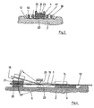
- a band-shaped tension member 1 for example, a carbon fiber-reinforced plastic lamella, is intended for attachment to the surface of a supporting structure, in the illustrated embodiment of a concrete structure 2. Likewise, the use in other structures, such as steel or wood, possible. Before being fixed to the concrete structure 2, the tension member 1 must be biased.
- the tension member 1 by means of a clamping plate 3, act on the multiple clamping bracket 4, fixed to a base plate 5, which is fixed by dowels 6 and an adhesive layer 7 in a recess 8 of the concrete structure 2.
- a base plate 9 by means of dowels 10 and an adhesive layer 11 defined in a recess 12 of the concrete structure 2.
- a clamping plate in the Fig. 1 and 2 not yet shown
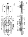
- the tensioning device 13 has a tensioning traverse 14, which is provided with two lugs 15, which are fastened on both sides of the tension member 1 by means of screws 16 releasably secured to the base plate 9.
- tension side On the tension traverse 14 are based on the base plate 9 side facing away (referred to in this context as "tension side") from two press elements 17, which are designed in the illustrated embodiment as a hydraulic cylinder.
- the two press members 17 are in the plane of the tension member 1. They press a clamping armature 18 away from the tension traverse 14.
- the clamping anchor 18 is guided on both sides of lateral guide rods 19, which are connected to the tension traverse 14. In its Spannend sued the clamping anchor 18 is fixed to the lateral guide rods 19, so that it is then supported even after the release of the press members 17 on the guide rods 19 on the tension traverse 14.
- another type of blocking can be chosen to the Support anchor 18.
- the support or blocking is in this embodiment in the plane of the tension member. 1
- the clamping anchor 18 has a lower plate 20 on which the tension member 1 rests.
- the tension member 1 is clamped by clamping bracket 21, clamping screws 22 and a clamping plate 23 against the lower plate 20 and secured in this manner to the clamping anchor 18.
- a guide support 24 is integral with the tension traverse 14, welded to this or otherwise, for example by means of screws rigidly attached to the tension traverse 14 and forms at its free end a lying at the top of the tension member 1 guide body 25 extending between the tension traverse 14 and the clamping anchor 18 and is arranged in span healedem distance to the tension traverse 14.
- the arranged on the upper side of the tension member 1 guide body 25 has laterally beyond the tension member 1 projecting side portions 26 which are releasably connected to a below the tension member 1 bracket 27, preferably via lateral screws 28.
- the guide body 25 does not necessarily have with the tension traverse 14 may be connected: it may also be attached in a stationary manner, for example, to the supporting structure, in this case to the concrete structure 2.
- a guide slot 29 is formed, which receives the tension member 1 slidably.
- the guide body 25 forms a deflection point for the tension member 1, the tension side is at a distance in front of the tension traverse 14.
Landscapes
- Architecture (AREA)
- Engineering & Computer Science (AREA)
- Civil Engineering (AREA)
- Structural Engineering (AREA)
- Mechanical Engineering (AREA)
- Chemical & Material Sciences (AREA)
- Chemical Kinetics & Catalysis (AREA)
- Electrochemistry (AREA)
- Reinforcement Elements For Buildings (AREA)
- Working Measures On Existing Buildindgs (AREA)
- Folding Of Thin Sheet-Like Materials, Special Discharging Devices, And Others (AREA)
- Basic Packing Technique (AREA)
- Knitting Machines (AREA)
- Tension Adjustment In Filamentary Materials (AREA)
- Sewing Machines And Sewing (AREA)
- Clamps And Clips (AREA)
- Shaping Of Tube Ends By Bending Or Straightening (AREA)
- Controlling Rewinding, Feeding, Winding, Or Abnormalities Of Webs (AREA)
- Registering, Tensioning, Guiding Webs, And Rollers Therefor (AREA)
Applications Claiming Priority (3)
| Application Number | Priority Date | Filing Date | Title |
|---|---|---|---|
| DE10249266 | 2002-10-23 | ||
| DE10249266A DE10249266B3 (de) | 2002-10-23 | 2002-10-23 | Spannvorrichtung für bandförmige Zugglieder |
| PCT/EP2003/009079 WO2004038128A1 (de) | 2002-10-23 | 2003-08-16 | Spannvorrichtung für bandförmige zugglieder |
Publications (2)
| Publication Number | Publication Date |
|---|---|
| EP1554447A1 EP1554447A1 (de) | 2005-07-20 |
| EP1554447B1 true EP1554447B1 (de) | 2010-07-21 |
Family
ID=31984425
Family Applications (1)
| Application Number | Title | Priority Date | Filing Date |
|---|---|---|---|
| EP03809255A Expired - Lifetime EP1554447B1 (de) | 2002-10-23 | 2003-08-16 | Spannvorrichtung für bandförmige zugglieder |
Country Status (9)
| Country | Link |
|---|---|
| US (1) | US20050252116A1 (da) |
| EP (1) | EP1554447B1 (da) |
| JP (1) | JP2006504005A (da) |
| KR (1) | KR20050032031A (da) |
| AT (1) | ATE474981T1 (da) |
| AU (1) | AU2003253415A1 (da) |
| DE (2) | DE10249266B3 (da) |
| DK (1) | DK1554447T3 (da) |
| WO (1) | WO2004038128A1 (da) |
Families Citing this family (18)
| Publication number | Priority date | Publication date | Assignee | Title |
|---|---|---|---|---|
| EP1507050A1 (de) * | 2003-08-13 | 2005-02-16 | Sika Technology AG | Krafteinleitungselement |
| CH701655B1 (de) * | 2008-02-08 | 2011-02-28 | Josef Scherer | Verfahren und Vorrichtung zum Vorspannen von Verstärkungslaminaten an Bauwerken. |
| US8904721B2 (en) * | 2008-06-12 | 2014-12-09 | University Of Utah Research Foundation | Anchoring, splicing and tensioning elongated reinforcement members |
| US8925279B2 (en) * | 2008-06-12 | 2015-01-06 | The University Of Utah Research Foundation | Anchoring, splicing and tensioning elongated reinforcement members |
| US10006477B2 (en) | 2010-04-13 | 2018-06-26 | University Of Utah Research Foundation | Sheet and rod attachment apparatus and system |
| EP2447446A1 (de) | 2010-10-28 | 2012-05-02 | Sika Technology AG | Endverankerung von Zuggliedern an Stahlbetonträgern |
| FR2969196B1 (fr) * | 2010-12-15 | 2014-02-07 | Soletanche Freyssinet | Procede de renforcement d'un ouvrage de construction mettant en oeuvre au moins une bande de renfort. |
| CH706630B1 (de) * | 2013-05-14 | 2013-12-31 | S & P Clever Reinforcement Company Ag | Verfahren zum Vorspannen eines Stahlbauwerkes sowie damit vorgespanntes Stahlbauwerk. |
| CN103541513B (zh) * | 2013-09-22 | 2016-04-20 | 沈阳建筑大学 | 一种内镶frp筋加固混凝土锚固件 |
| AU2016282937A1 (en) * | 2015-06-26 | 2018-01-18 | Danmarks Tekniske Universitet | Anchorage device |
| CN105781123A (zh) * | 2016-05-06 | 2016-07-20 | 西南交通大学 | 碳纤维板机械夹持锚具以及加固装置 |
| CN105862608B (zh) * | 2016-05-20 | 2017-09-19 | 东南大学 | 一种预应力纤维板加固梁板的自动化张拉系统及方法 |
| CN106285038B (zh) * | 2016-09-23 | 2023-01-24 | 长沙理工大学 | 一种分离式预应力碳纤维布张拉粘贴装置及方法 |
| DE102017203645B4 (de) * | 2017-03-07 | 2020-07-02 | KB Vorspann-Technik GmbH | System zum Vorspannen eines Turmbauwerks |
| EP3372753B1 (de) * | 2017-03-07 | 2020-02-19 | KB Vorspann-Technik GmbH | Verfahren, arretiervorrichtung und system zum vorspannen eines turmbauwerks |
| US11186991B2 (en) * | 2018-10-31 | 2021-11-30 | Shenzhen University | Early warning device and ductility control method for prestressed FRP reinforced structure |
| CN111794545B (zh) * | 2020-06-16 | 2024-11-01 | 深圳大学 | 一种预应力加固装置及预应力加载施工方法 |
| CN117449608B (zh) * | 2023-12-26 | 2024-03-12 | 福建理工大学 | 一种用于弧面结构的自动调平碳纤维板预应力张拉装置 |
Family Cites Families (11)
| Publication number | Priority date | Publication date | Assignee | Title |
|---|---|---|---|---|
| US3290840A (en) * | 1962-07-20 | 1966-12-13 | Prescon Corp | Method and means for chemically prestressing concrete |
| FR1426231A (fr) * | 1964-11-25 | 1966-01-28 | Union Tech Interfederale Du Ba | Perfectionnements aux éléments de constructions renforcés |
| BE789655R (fr) * | 1965-05-21 | 1973-04-04 | Birguer Alexandre Rue Lincoln | Poutres composites et precontraintes en acier-beton et leur procede de |
| JP2700268B2 (ja) | 1989-04-04 | 1998-01-19 | 東急建設株式会社 | 炭素繊維強化プラスチック平面板の定着方法及び定着装置 |
| MX9200051A (es) * | 1992-01-07 | 1993-07-01 | Jose Luis Siller Franco | Concector por friccion mejorado para anclar acero de refuerzo a tension en elementos de concreto preesforzado o reforzado. |
| CH687399A5 (de) * | 1992-04-06 | 1996-11-29 | Eidgenoessische Materialpruefung | Verfahren und Vorrichtung zur Schubverstaerkung an einem Bauwerkteil. |
| DK0803020T3 (da) * | 1995-01-09 | 1999-06-14 | Empa | Befæstigelse af forstærkningslameller |
| US5768847A (en) * | 1995-05-15 | 1998-06-23 | Policelli; Frederick J. | Concrete reinforcing devices, concrete reinforced structures, and method of and apparatus for producing such devices and structures |
| DE19742210A1 (de) * | 1997-09-24 | 1999-03-25 | Goehler Bernhard Dipl Ing | Verfahren und bandförmiges Zugglied zur Ertüchtigung und/oder Sanierung von Stahlbeton- oder Spannbeton-Tragwerken sowie Vorrichtung zur Durchführung des Vefahrens |
| DE19849605A1 (de) * | 1998-10-28 | 2000-05-04 | Goehler Andrae Und Partner Ber | Spannvorrichtung für ein bandförmiges Zugglied |
| DE19944573A1 (de) | 1999-09-17 | 2001-03-22 | Josef Scherer | Verstärkungsanordnung für Bauwerke und Bauwerksteile |
-
2002
- 2002-10-23 DE DE10249266A patent/DE10249266B3/de not_active Expired - Fee Related
-
2003
- 2003-08-16 AT AT03809255T patent/ATE474981T1/de active
- 2003-08-16 AU AU2003253415A patent/AU2003253415A1/en not_active Abandoned
- 2003-08-16 US US10/517,988 patent/US20050252116A1/en not_active Abandoned
- 2003-08-16 DE DE50312912T patent/DE50312912D1/de not_active Expired - Lifetime
- 2003-08-16 JP JP2004545755A patent/JP2006504005A/ja not_active Withdrawn
- 2003-08-16 WO PCT/EP2003/009079 patent/WO2004038128A1/de not_active Ceased
- 2003-08-16 EP EP03809255A patent/EP1554447B1/de not_active Expired - Lifetime
- 2003-08-16 KR KR1020047018154A patent/KR20050032031A/ko not_active Abandoned
- 2003-08-16 DK DK03809255.7T patent/DK1554447T3/da active
Also Published As
| Publication number | Publication date |
|---|---|
| EP1554447A1 (de) | 2005-07-20 |
| DE10249266B3 (de) | 2004-04-08 |
| ATE474981T1 (de) | 2010-08-15 |
| KR20050032031A (ko) | 2005-04-06 |
| JP2006504005A (ja) | 2006-02-02 |
| DK1554447T3 (da) | 2010-10-04 |
| WO2004038128A1 (de) | 2004-05-06 |
| AU2003253415A1 (en) | 2004-05-13 |
| DE50312912D1 (de) | 2010-09-02 |
| US20050252116A1 (en) | 2005-11-17 |
Similar Documents
| Publication | Publication Date | Title |
|---|---|---|
| DE10249266B3 (de) | Spannvorrichtung für bandförmige Zugglieder | |
| EP1125031B1 (de) | Spannvorrichtung für ein bandförmiges zugglied | |
| DE69805747T3 (de) | Spannvorrichtung für eine holmlose Spritzgiessmaschine | |
| EP2489808B1 (de) | Bewehrungselement für die Aufnahme von Kräften in Betonelementen, die durch Stützelemente abgestützt sind | |
| DE10341376A1 (de) | Verankerung für bandförmige Zugglieder an Tragwerken | |
| DE2505235C2 (de) | Sattelplatte zur Befestigung von Druckplatten an Rotations-Hochdruckmaschinen | |
| DE3604071A1 (de) | Druckplattenspanneinrichtung in einer grube eines plattenzylinders einer rotationsdruckmaschine | |
| DE2021780B2 (de) | Verfahren zur Anpassung der Bogenführung eines aus einer Stranggießkokille austretenden Stranges | |
| DE2049211C3 (de) | Greifvorrichtung für Bauteile | |
| EP0002814A1 (de) | Betonschalung aus Schaltafeln mit Keilverbindung | |
| EP0012265B1 (de) | Vorrichtung zur Schienenbefestigung | |
| AT391916B (de) | Ausleger mit horizontaler seilabspannung | |
| DE1709306C3 (de) | Führung für Gleitschalungen | |
| WO1991004859A1 (de) | Vorrichtung zum positionsgenauen spannen einer druckplatte auf einem druckzylinder | |
| DE2607212B2 (de) | Kern zur Bildung eines Hohlraumes in einer Gießform herzustellenden plattenartigen Bauelementen | |
| DE2907116C2 (de) | Vorrichtung für die Montage einer Türzarge | |
| DE854187C (de) | Grubenstempel | |
| DE1011612B (de) | Vorrichtung zum Zusammenpressen eines plattenfoermigen Koerpers, z.B. eines Furnierstueckes | |
| DE3421148C2 (da) | ||
| DE7341458U (de) | Schnellspannvorrichtung | |
| DE2237651C3 (de) | Bandspanner | |
| DE934341C (de) | Grubenstempel aus Stahl oder Leichtmetall | |
| AT377721B (de) | Montagevorrichtung zum verbinden von schubladen- teilen | |
| DE2055457C3 (de) | Vulkanisierpresse für Fördergurte und ähnliche bandförmige Gummierzeugnisse | |
| DE19544788A1 (de) | Spritzgießmaschine mit Zweiplatten-Schließeinheit |
Legal Events
| Date | Code | Title | Description |
|---|---|---|---|
| PUAI | Public reference made under article 153(3) epc to a published international application that has entered the european phase |
Free format text: ORIGINAL CODE: 0009012 |
|
| 17P | Request for examination filed |
Effective date: 20041006 |
|
| AK | Designated contracting states |
Kind code of ref document: A1 Designated state(s): AT BE BG CH CY CZ DE DK EE ES FI FR GB GR HU IE IT LI LU MC NL PT RO SE SI SK TR |
|
| AX | Request for extension of the european patent |
Extension state: AL LT LV MK |
|
| DAX | Request for extension of the european patent (deleted) | ||
| REG | Reference to a national code |
Ref country code: HK Ref legal event code: DE Ref document number: 1077862 Country of ref document: HK |
|
| RIN1 | Information on inventor provided before grant (corrected) |
Inventor name: ANDRAE, HANS-PETER Inventor name: MAIER, MARKUS |
|
| 17Q | First examination report despatched |
Effective date: 20090930 |
|
| GRAP | Despatch of communication of intention to grant a patent |
Free format text: ORIGINAL CODE: EPIDOSNIGR1 |
|
| GRAS | Grant fee paid |
Free format text: ORIGINAL CODE: EPIDOSNIGR3 |
|
| GRAA | (expected) grant |
Free format text: ORIGINAL CODE: 0009210 |
|
| AK | Designated contracting states |
Kind code of ref document: B1 Designated state(s): AT BE BG CH CY CZ DE DK EE ES FI FR GB GR HU IE IT LI LU MC NL PT RO SE SI SK TR |
|
| REG | Reference to a national code |
Ref country code: GB Ref legal event code: FG4D Free format text: NOT ENGLISH |
|
| REG | Reference to a national code |
Ref country code: CH Ref legal event code: EP |
|
| REG | Reference to a national code |
Ref country code: IE Ref legal event code: FG4D |
|
| REG | Reference to a national code |
Ref country code: CH Ref legal event code: NV Representative=s name: ISLER & PEDRAZZINI AG |
|
| REF | Corresponds to: |
Ref document number: 50312912 Country of ref document: DE Date of ref document: 20100902 Kind code of ref document: P |
|
| REG | Reference to a national code |
Ref country code: DK Ref legal event code: T3 |
|
| REG | Reference to a national code |
Ref country code: NL Ref legal event code: VDEP Effective date: 20100721 |
|
| PG25 | Lapsed in a contracting state [announced via postgrant information from national office to epo] |
Ref country code: NL Free format text: LAPSE BECAUSE OF FAILURE TO SUBMIT A TRANSLATION OF THE DESCRIPTION OR TO PAY THE FEE WITHIN THE PRESCRIBED TIME-LIMIT Effective date: 20100721 Ref country code: FI Free format text: LAPSE BECAUSE OF FAILURE TO SUBMIT A TRANSLATION OF THE DESCRIPTION OR TO PAY THE FEE WITHIN THE PRESCRIBED TIME-LIMIT Effective date: 20100721 |
|
| REG | Reference to a national code |
Ref country code: IE Ref legal event code: FD4D |
|
| BERE | Be: lapsed |
Owner name: LEONHARDT, ANDRA UND PARTNER BERATENDE INGENIEURE Effective date: 20100831 |
|
| PG25 | Lapsed in a contracting state [announced via postgrant information from national office to epo] |
Ref country code: PT Free format text: LAPSE BECAUSE OF FAILURE TO SUBMIT A TRANSLATION OF THE DESCRIPTION OR TO PAY THE FEE WITHIN THE PRESCRIBED TIME-LIMIT Effective date: 20101122 Ref country code: BG Free format text: LAPSE BECAUSE OF FAILURE TO SUBMIT A TRANSLATION OF THE DESCRIPTION OR TO PAY THE FEE WITHIN THE PRESCRIBED TIME-LIMIT Effective date: 20101021 Ref country code: SI Free format text: LAPSE BECAUSE OF FAILURE TO SUBMIT A TRANSLATION OF THE DESCRIPTION OR TO PAY THE FEE WITHIN THE PRESCRIBED TIME-LIMIT Effective date: 20100721 Ref country code: CY Free format text: LAPSE BECAUSE OF FAILURE TO SUBMIT A TRANSLATION OF THE DESCRIPTION OR TO PAY THE FEE WITHIN THE PRESCRIBED TIME-LIMIT Effective date: 20100721 |
|
| PG25 | Lapsed in a contracting state [announced via postgrant information from national office to epo] |
Ref country code: MC Free format text: LAPSE BECAUSE OF NON-PAYMENT OF DUE FEES Effective date: 20100831 Ref country code: SE Free format text: LAPSE BECAUSE OF FAILURE TO SUBMIT A TRANSLATION OF THE DESCRIPTION OR TO PAY THE FEE WITHIN THE PRESCRIBED TIME-LIMIT Effective date: 20100721 Ref country code: GR Free format text: LAPSE BECAUSE OF FAILURE TO SUBMIT A TRANSLATION OF THE DESCRIPTION OR TO PAY THE FEE WITHIN THE PRESCRIBED TIME-LIMIT Effective date: 20101022 |
|
| PG25 | Lapsed in a contracting state [announced via postgrant information from national office to epo] |
Ref country code: IE Free format text: LAPSE BECAUSE OF FAILURE TO SUBMIT A TRANSLATION OF THE DESCRIPTION OR TO PAY THE FEE WITHIN THE PRESCRIBED TIME-LIMIT Effective date: 20100721 |
|
| PLBE | No opposition filed within time limit |
Free format text: ORIGINAL CODE: 0009261 |
|
| STAA | Information on the status of an ep patent application or granted ep patent |
Free format text: STATUS: NO OPPOSITION FILED WITHIN TIME LIMIT |
|
| PG25 | Lapsed in a contracting state [announced via postgrant information from national office to epo] |
Ref country code: SK Free format text: LAPSE BECAUSE OF FAILURE TO SUBMIT A TRANSLATION OF THE DESCRIPTION OR TO PAY THE FEE WITHIN THE PRESCRIBED TIME-LIMIT Effective date: 20100721 Ref country code: CZ Free format text: LAPSE BECAUSE OF FAILURE TO SUBMIT A TRANSLATION OF THE DESCRIPTION OR TO PAY THE FEE WITHIN THE PRESCRIBED TIME-LIMIT Effective date: 20100721 Ref country code: RO Free format text: LAPSE BECAUSE OF FAILURE TO SUBMIT A TRANSLATION OF THE DESCRIPTION OR TO PAY THE FEE WITHIN THE PRESCRIBED TIME-LIMIT Effective date: 20100721 Ref country code: EE Free format text: LAPSE BECAUSE OF FAILURE TO SUBMIT A TRANSLATION OF THE DESCRIPTION OR TO PAY THE FEE WITHIN THE PRESCRIBED TIME-LIMIT Effective date: 20100721 Ref country code: IT Free format text: LAPSE BECAUSE OF FAILURE TO SUBMIT A TRANSLATION OF THE DESCRIPTION OR TO PAY THE FEE WITHIN THE PRESCRIBED TIME-LIMIT Effective date: 20100721 |
|
| 26N | No opposition filed |
Effective date: 20110426 |
|
| PG25 | Lapsed in a contracting state [announced via postgrant information from national office to epo] |
Ref country code: ES Free format text: LAPSE BECAUSE OF FAILURE TO SUBMIT A TRANSLATION OF THE DESCRIPTION OR TO PAY THE FEE WITHIN THE PRESCRIBED TIME-LIMIT Effective date: 20101101 |
|
| PG25 | Lapsed in a contracting state [announced via postgrant information from national office to epo] |
Ref country code: BE Free format text: LAPSE BECAUSE OF NON-PAYMENT OF DUE FEES Effective date: 20100831 |
|
| REG | Reference to a national code |
Ref country code: DE Ref legal event code: R097 Ref document number: 50312912 Country of ref document: DE Effective date: 20110426 |
|
| REG | Reference to a national code |
Ref country code: HK Ref legal event code: WD Ref document number: 1077862 Country of ref document: HK |
|
| PG25 | Lapsed in a contracting state [announced via postgrant information from national office to epo] |
Ref country code: HU Free format text: LAPSE BECAUSE OF FAILURE TO SUBMIT A TRANSLATION OF THE DESCRIPTION OR TO PAY THE FEE WITHIN THE PRESCRIBED TIME-LIMIT Effective date: 20110122 Ref country code: LU Free format text: LAPSE BECAUSE OF NON-PAYMENT OF DUE FEES Effective date: 20100816 |
|
| PG25 | Lapsed in a contracting state [announced via postgrant information from national office to epo] |
Ref country code: TR Free format text: LAPSE BECAUSE OF FAILURE TO SUBMIT A TRANSLATION OF THE DESCRIPTION OR TO PAY THE FEE WITHIN THE PRESCRIBED TIME-LIMIT Effective date: 20100721 |
|
| REG | Reference to a national code |
Ref country code: DE Ref legal event code: R082 Ref document number: 50312912 Country of ref document: DE Representative=s name: KATSCHER HABERMANN PATENTANWAELTE, DE |
|
| REG | Reference to a national code |
Ref country code: DE Ref legal event code: R082 Ref document number: 50312912 Country of ref document: DE Representative=s name: KATSCHER HABERMANN PATENTANWAELTE, DE Effective date: 20130925 Ref country code: DE Ref legal event code: R081 Ref document number: 50312912 Country of ref document: DE Owner name: LEONHARDT, ANDRAE UND PARTNER BERATENDE INGENI, DE Free format text: FORMER OWNER: LEONHARDT, ANDRAE UND PARTNER BERATENDE INGENIEURE VBI GMBH, 70192 STUTTGART, DE Effective date: 20130925 Ref country code: DE Ref legal event code: R082 Ref document number: 50312912 Country of ref document: DE Representative=s name: PATENTANWAELTE KATSCHER HABERMANN, DE Effective date: 20130925 |
|
| REG | Reference to a national code |
Ref country code: CH Ref legal event code: PFA Owner name: LEONHARDT, ANDRAE UND PARTNER INGENIEURE VBI A, DE Free format text: FORMER OWNER: LEONHARDT, ANDRAE UND PARTNER BERATENDE INGENIEURE VBI GMBH, DE |
|
| REG | Reference to a national code |
Ref country code: AT Ref legal event code: HC Ref document number: 474981 Country of ref document: AT Kind code of ref document: T Owner name: LEONHARDT, ANDRAE UND PARTNER BERATENDE INGENI, DE Effective date: 20150113 |
|
| REG | Reference to a national code |
Ref country code: FR Ref legal event code: CJ Effective date: 20150130 Ref country code: FR Ref legal event code: CA Effective date: 20150130 |
|
| REG | Reference to a national code |
Ref country code: FR Ref legal event code: PLFP Year of fee payment: 13 |
|
| PGFP | Annual fee paid to national office [announced via postgrant information from national office to epo] |
Ref country code: DE Payment date: 20150807 Year of fee payment: 13 Ref country code: GB Payment date: 20150824 Year of fee payment: 13 Ref country code: CH Payment date: 20150824 Year of fee payment: 13 Ref country code: DK Payment date: 20150825 Year of fee payment: 13 |
|
| PGFP | Annual fee paid to national office [announced via postgrant information from national office to epo] |
Ref country code: AT Payment date: 20150827 Year of fee payment: 13 Ref country code: FR Payment date: 20150824 Year of fee payment: 13 |
|
| REG | Reference to a national code |
Ref country code: DE Ref legal event code: R119 Ref document number: 50312912 Country of ref document: DE |
|
| REG | Reference to a national code |
Ref country code: DK Ref legal event code: EBP Effective date: 20160831 |
|
| REG | Reference to a national code |
Ref country code: CH Ref legal event code: PL |
|
| REG | Reference to a national code |
Ref country code: AT Ref legal event code: MM01 Ref document number: 474981 Country of ref document: AT Kind code of ref document: T Effective date: 20160816 |
|
| GBPC | Gb: european patent ceased through non-payment of renewal fee |
Effective date: 20160816 |
|
| PG25 | Lapsed in a contracting state [announced via postgrant information from national office to epo] |
Ref country code: CH Free format text: LAPSE BECAUSE OF NON-PAYMENT OF DUE FEES Effective date: 20160831 Ref country code: LI Free format text: LAPSE BECAUSE OF NON-PAYMENT OF DUE FEES Effective date: 20160831 |
|
| REG | Reference to a national code |
Ref country code: FR Ref legal event code: ST Effective date: 20170428 |
|
| PG25 | Lapsed in a contracting state [announced via postgrant information from national office to epo] |
Ref country code: AT Free format text: LAPSE BECAUSE OF NON-PAYMENT OF DUE FEES Effective date: 20160816 |
|
| PG25 | Lapsed in a contracting state [announced via postgrant information from national office to epo] |
Ref country code: FR Free format text: LAPSE BECAUSE OF NON-PAYMENT OF DUE FEES Effective date: 20160831 Ref country code: DK Free format text: LAPSE BECAUSE OF NON-PAYMENT OF DUE FEES Effective date: 20160831 Ref country code: DE Free format text: LAPSE BECAUSE OF NON-PAYMENT OF DUE FEES Effective date: 20170301 Ref country code: GB Free format text: LAPSE BECAUSE OF NON-PAYMENT OF DUE FEES Effective date: 20160816 |