EP1552925B1 - Support pour une cartouche à encre - Google Patents
Support pour une cartouche à encre Download PDFInfo
- Publication number
- EP1552925B1 EP1552925B1 EP05000277A EP05000277A EP1552925B1 EP 1552925 B1 EP1552925 B1 EP 1552925B1 EP 05000277 A EP05000277 A EP 05000277A EP 05000277 A EP05000277 A EP 05000277A EP 1552925 B1 EP1552925 B1 EP 1552925B1
- Authority
- EP
- European Patent Office
- Prior art keywords
- cover
- ink cartridge
- cartridge holder
- hinge arm
- bearing base
- Prior art date
- Legal status (The legal status is an assumption and is not a legal conclusion. Google has not performed a legal analysis and makes no representation as to the accuracy of the status listed.)
- Expired - Fee Related
Links
Images


Classifications
-
- B—PERFORMING OPERATIONS; TRANSPORTING
- B41—PRINTING; LINING MACHINES; TYPEWRITERS; STAMPS
- B41F—PRINTING MACHINES OR PRESSES
- B41F31/00—Inking arrangements or devices
- B41F31/02—Ducts, containers, supply or metering devices
Definitions
- the invention relates to a color cartridge container for supplying ink to printing machine inking units, with a lid tightly sealing the ink cartridge container, which makes it possible to build up an air pressure for squeezing ink from a cartridge in the interior of the container, with a locking mechanism for locking the lid in the closed position and unlocking when opening the lid and a valve for controlling the supply and discharge of air with respect to the interior of the container, which is controllable in dependence on the locked or unlocked position of the lid.
- ink cartridges are used, from which the ink can be squeezed out by means of suitable facilities.
- Auspreßvoriquesen known, for example, consist of a cartridge receiving a container that can be sealed by a lid. After closing the container, the ink can be squeezed out of the cartridge through the open container bottom by introducing compressed air.
- the present invention relates.
- a pneumatic cartridge ejecting device of the type mentioned is known.
- the lid can be locked with a bayonet lock on the tubular container.
- the lid has an air connection through which compressed air can be introduced into the upper area of the container below the lid.
- the resulting compressed air cushion presses on the cartridge piston and drives it down so that the color is pressed down out of the cartridge.
- the document is particularly concerned with the sealing of an annular gap, which may remain in the container between the cartridge and the container in imprecise fit of the cartridge. Lack of other information, it is assumed that the lid is placed by hand on the container and that the supply and the discharge of the compressed air is controlled manually.
- the DE 296 02 801 U1 is also concerned with a device for squeezing out cartridges. Also in this case, it is a container that can be closed by a lid. It is about eliminating sealing problems, with the aim to be able to squeeze cartridges with different formats. The closing of the lid and the control of the compressed air should obviously be done manually.
- the EP 716 923 B1 describes a further squeezing device for cartridges, which comprises a cylindrical container which can be closed by a cover flap, to which a compressed air line can be connected.
- the closing and opening of the lid flap should obviously be done by hand. The same should apply to the supply and discharge of compressed air.
- the DE 198 54 494 C2 (Preamble of claim 1) describes a further cartridge receptacle with a lid closing this and a valve for supplying compressed air through the lid.
- This document is mainly about operating safety. It should be ensured, mutatis mutandis, that compressed air is supplied only when the lid is properly closed, and on the other hand, the compressed air cushion is removed before the lid is opened.
- a valve is provided for the air control, which is connected via an adjusting device with the lid, so that the valve when closing the cartridge receptacle with the lid is actuated.
- the invention has the object of providing a color cartridge container in such a way that it is suitable for a high degree of automation of the cartridge replacement process.
- a rotary actuator for automatically opening and closing the lid which is designed such that it brings the lid in a closed position in a first movement phase and locked in a second phase of movement the lid and the air valve switches and reversed when opened accordingly.
- the ink cartridge container according to the invention is suitable for integration into a system for fully automatic ink supply.
- a system for fully automatic ink supply For example, it is possible to have ink cartridges ready in a magazine and, after opening the lid of the ink cartridge container according to the present application, replace an empty cartridge with a full cartridge. Since the opening and closing of the lid, its locking and unlocking and the control of the supply and discharge of air are performed by one and the same pivot drive, it is possible to coordinate the three operations so that the required reliability is achieved. More details will become apparent later in the description.
- the pivot drive comprises a drive cylinder with extendable piston rod which is mounted on a console connected to the ink cartridge container on which a hinge mechanism of the lid is mounted in a first pivot axis.
- the hinge mechanism includes a hinge arm having a slot in which a transverse pin connected to the piston rod is guided, which is lockable in the retracted end position of the slot and remains locked until the lid is closed.
- this movement phase which has been referred to here as the second phase, the displacement of the transverse pin causes a locking of the lid and a switching of the valve.
- a bearing block is mounted, which is pivotable together with the hinge arm and on which a pivot lever is mounted in a second pivot axis, which is mounted parallel to the first pivot axis on the bearing block.
- the bearing block which is rigidly connected to the hinge arm, has a slot in which the transverse bolt also enters. This slot is congruent with the slot of the hinge arm. After unlocking the cross bolt this is also moved in the slot of the bearing block. This displacement pivots the pivot lever with respect to the bearing block.
- the pivot lever is connected on the one hand with a locking mechanism of the lid and on the other hand with the valve for the air control.
- the locking of the transverse pin is preferably carried out in that the pivot lever is locked with respect to the bearing block. Since the cross bolt is firmly connected to the pivot lever, the transverse bolt is fixed in this way, so that it can not move in the slot of the bearing block in the slot of the hinge arm.
- hinge arm and bearing block The entire arrangement of hinge arm and bearing block is mounted in a continuous axis, the first pivot axis on the console. It is folded in the feed direction when the lid is closed. The unlocking of the transverse bolt takes place in that during this folding the locking pin, which causes the locking, is pushed back by an unlocking member which is arranged on the console.
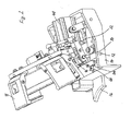
- Fig. 1 shows a lid of a color cartridge container according to the invention, which is generally designated 10.
- the cover 10 is supported by a first pivot axis 12 on a bracket 14 so that it can be folded from the illustrated, upright position to the left to a position in which it closes a container, not shown.
- the position of the container is indicated by the arcuate edge line of a connecting plate 16 only partially shown, which connects the console 14 fixed to the container.
- the cover 10 distributed on the circumference has a total of four closing jaws 18,20,22,24, the claw-shaped not shown edge elements on the upper edge of the container, not shown, and set the lid in this way on the container. This locking mechanism will be discussed in more detail later.
- the first pivot axis 12 runs across the entire width of the bracket 14 and is mounted at its two ends in bearings 26,28. Between these two bearings is a hinge arm 30, which is connected through an opening of the lower closing jaw 22 firmly fixed to the lid 10, as in Fig. 1 at least hinted at.
- the hinge arm consists of three parallel elements which are subdivided by slots 32, 34 into which the two fingers of a clevis 36 enter ( Fig. 4 ), which at the end of a piston rod 38 of a pneumatic cylinder 40 ( Fig. 5 ) which is the driving source for both opening and closing the lid, locking and unlocking the lid, and supplying and discharging air with respect to the container.
- the hinge arm 30 forms a coherent unit with a bearing block 42, which as well as the hinge arm and parallel to this from a common, pivotable about the first pivot axis 12 base body 44.
- the hinge arm 30 and the bearing block 42 have congruent elongated holes 46,48, which are traversed over the entire length of the arrangement of hinge arm and bearing block of a cross bolt 50.
- the transverse pin 50 is displaceable by means of the clevis 36 of the piston rod 38 in the oblong holes 46,48 under certain conditions transversely to its longitudinal axis, as will be explained in more detail later.
- the piston rod 38 With the lid 10 open, the piston rod 38 is in the retracted position, and the cross pin 50 is in the rear end position of the slots 46,48 of the hinge arm 30 and the bearing block 42. In this position, the cross bolt during the first phase of movement of the pivot mechanism according to the locked present invention.
- the cross pin is thus fixed in the hinge arm 30 so that it pivots the hinge arm 30 about the first pivot axis 12 when advancing the piston rod 38 and thus folds the lid 10 in the closed position.
- a pivot lever 52 is provided, which is pivotally mounted with respect to the bearing block 42 in a second pivot axis 54 which is parallel to the first pivot axis 12.
- the transverse bolt 50 runs in the slot 48 of the bearing block 42.
- the slot 48 and thus also the slot 46 thus describe a circular arc about the second pivot axis 54th
- a Entriegelungsblock 66 with an unspecified groove on which the locking bolt 58 strikes when folding the bearing block 42 on the surface of the console 14.
- the locking bolt has in this area a frusto-conical transition surface 68 which meets the left edge of the non-designated groove and thereby by the unlocking block 66 to the left in Fig. 6 is pushed back against the pressure of the compression spring 60.
- the pivot lever 52 is unlocked with respect to the bearing block 42.
- the transverse bolt is advanced in the oblong holes 46, 48. This has no effect with respect to the hinge arm 30 and the cover 10.
- a pull rod 70 is fixed by means of a ball joint 72 which is connected on the other side by means of another ball joint 74 with a collar 76 which is rotatably guided on the lid 10 in a manner not shown.
- the pull rod 70 is right in Fig. 3 and 4 drawn.
- guide bolts 78,80,82,84 are fixed, which protrude perpendicularly from the adjusting ring and in guide slots 86,88,90,92 on an upper, inwardly directed flange 94,96,98,100 of the closing jaws 18, 20,22,24 run.
- the closing jaws 18, 20, 22, 24 are in horizontal axes 102 (FIG. Fig. 4 ) is pivotally mounted on the outer periphery of the lid.
- the closing jaws are 18,20,22,24 folded up against the container on which they engage behind counter elements not shown.
- the mechanism first performs a flow before it releases the lid. This connection will be discussed below.
- the bearing block 42 When folding the hinge arm 30 and the bearing block 42 during the first phase of movement during extension of the piston rod 38, the bearing block 42 hits on approaching the surface of the console 14 with a groove 104 on the underside of the pivot lever 52 to an L-shaped bent end of a slider 106, which is slidably guided on the surface of the console 14 ( Fig. 5 ).
- This slider controls a three-way valve 110 which controls the air supply to the interior of the container and the discharge of the air from inside the container.
- Fig. 5 It can be seen particularly clearly that the pneumatic cylinder on the bracket 14 in a pivot axis 112 by means of two bearings 114,116 is pivotally mounted.
- the piston rod 38 and with this the clevis 36 can thus follow the movement of the transverse pin 50 in the slots 46,48 and the pivoting movement of the hinge arm 30, without causing tension.
- the function of the three-way valve 110 does not require extensive explanation.
- the valve has a non-designated inlet for compressed air and an outlet for conveying the compressed air in the cartridge container and a third output, which allows to reduce the compressed air cushion in the container to the environment.
- appropriate line connections are provided, which are not shown in the drawing.
Claims (10)
- Réservoir de cartouche d'encre pour alimenter des mécanismes d'encre de machines d'impression, comprenant un couvercle (10) qui ferme le réservoir de cartouche d'encre de manière étanche et qui permet d'établir une pression d'air dans le compartiment intérieur du réservoir pour l'éjection par pression de l'encre depuis une cartouche, comprenant un mécanisme de verrouillage pour verrouiller le couvercle dans la position fermée et pour le déverrouiller lors de l'ouverture du couvercle ainsi qu'une soupape (110) pour commander l'apport et l'évacuation de l'air en référence à l'intérieur du réservoir qui peut être commandé en fonction de la position verrouillée ou déverrouillée du couvercle, dans lequel la pression dans le réservoir est tout d'abord annulée avant que le couvercle soit déverrouillé, caractérisé en ce qu'un entraînement pivotant (30, 40, 42, 52) est prévu pour l'ouverture et la fermeture automatiques du couvercle (10) et est réalisé de telle sorte qu'il amène le couvercle (10) dans la position fermée dans une première phase de mouvement et qu'il- verrouille le couvercle (10) dans une seconde phase de mouvement et qu'il enclenche la soupape d'air (110) et la déplace à l'inverse en conséquence lors de l'ouverture.
- Réservoir de cartouche d'encre selon la revendication 1, caractérisé en ce que l'entraînement pivotant comporte un cylindre d'entraînement (40) muni d'une tige de piston qui peut être déployée (38) et qui est fixée sur une console (14), laquelle est reliée au réservoir de cartouche d'encre et sur laquelle un mécanisme à charnière (30, 36) du couvercle (10) est aussi monté dans un premier axe de pivotement (12), dans lequel ledit mécanisme à charnière comporte un bras de charnière (30) qui présente un trou oblong (46) dans lequel est guidé un boulon transversal (50) qui est relié à la tige de piston (38) du cylindre d'entraînement (40) et qui est verrouillé dans la position finale en retrait du trou oblong (46, 48) et qui reste verrouillé jusqu'à la fermeture du couvercle.
- Réservoir de cartouche d'encre selon la revendication 2, caractérisé en ce qu'une console d'appui (42) est montée sur le bras de charnière (30), laquelle peut être pivotée conjointement avec le bras de charnière et sur laquelle est monté un levier de pivotement (52) dans un second axe de pivotement (54) qui est monté parallèlement au premier axe de pivotement (12) sur la console d'appui (52).
- Réservoir de cartouche d'encre selon la revendication 3, caractérisé en ce que la console d'appui (42) est traversée en coïncidence avec le bras de charnière (30) du couvercle (10) par un trou oblong (48) dans lequel le boulon transversal (50) est également guidé.
- Réservoir de cartouche d'encre selon l'une ou l'autre des revendications 3 et 4, caractérisé en ce que le levier de pivotement (52) peut être verrouillé en référence au pivotement autour du second axe de pivotement (54).
- Réservoir de cartouche d'encre selon la revendication 5, caractérisé en ce que le verrouillage est annulé si le bras de charnière (30) du couvercle (10) est parvenu et si la console d'appui (42) avec celui-ci est parvenue dans une position avancée par la tige de piston (38) dans laquelle le couvercle (10) est fermé.
- Réservoir de cartouche d'encre selon l'une ou l'autre des revendications 5 et 6, caractérisé en ce que le verrouillage du levier de pivotement (52) a lieu en référence à la console d'appui (42).
- Réservoir de cartouche d'encre selon l'une ou l'autre des revendications 6 et 7, caractérisé en ce que le verrouillage du levier de pivotement (52) peut être annulé si le système constitué du bras de charnière (30) et de la console d'appui (42) est rabattu sur la console (14) dans le cadre du déploiement de la tige de piston (38).
- Réservoir de cartouche d'encre selon la revendication 8, caractérisé en ce qu'un boulon de pêne (58) est prévu, lequel relie la console d'appui (42) et le levier de pivotement (52) sous une pression de ressort et lequel peut être déverrouillé lors du rabattement du système constitué du bras de charnière (30) et de la console d'appui (42) sur la console (14) par un bloc de déverrouillage (66).
- Réservoir de cartouche d'encre selon l'une des revendications 3 à 9, caractérisé en ce que le levier de pivotement (52) vient en engagement avec une coulisse (108) lors du rabattement du système constitué du bras de charnière (30) et de la console d'appui (42) sur la surface de la console (14), dans lequel ladite coulisse exécute, lors du pivotement du levier de pivotement, un déplacement longitudinal au moyen duquel la soupape (110) peut être commandée.
Applications Claiming Priority (2)
| Application Number | Priority Date | Filing Date | Title |
|---|---|---|---|
| DE102004001750 | 2004-01-12 | ||
| DE102004001750A DE102004001750B3 (de) | 2004-01-12 | 2004-01-12 | Farbkartuschen-Behälter |
Publications (2)
| Publication Number | Publication Date |
|---|---|
| EP1552925A1 EP1552925A1 (fr) | 2005-07-13 |
| EP1552925B1 true EP1552925B1 (fr) | 2009-10-28 |
Family
ID=34485654
Family Applications (1)
| Application Number | Title | Priority Date | Filing Date |
|---|---|---|---|
| EP05000277A Expired - Fee Related EP1552925B1 (fr) | 2004-01-12 | 2005-01-07 | Support pour une cartouche à encre |
Country Status (4)
| Country | Link |
|---|---|
| US (1) | US7025447B2 (fr) |
| EP (1) | EP1552925B1 (fr) |
| JP (1) | JP4160054B2 (fr) |
| DE (1) | DE102004001750B3 (fr) |
Families Citing this family (4)
| Publication number | Priority date | Publication date | Assignee | Title |
|---|---|---|---|---|
| CN101698371B (zh) * | 2009-10-24 | 2011-05-25 | 黄景温 | 零调校移印机油盘装卸装置 |
| WO2019078899A1 (fr) | 2017-10-20 | 2019-04-25 | Hewlett-Packard Development Company, L.P. | Capuchons de cartouche d'encre |
| WO2019078898A1 (fr) | 2017-10-20 | 2019-04-25 | Hewlett-Packard Development Company, L.P. | Liaison de clapet et de capuchon de réservoir d'encre |
| WO2019078900A1 (fr) * | 2017-10-20 | 2019-04-25 | Hewlett-Packard Development Company, L.P. | Séquençage de clapet et de joint de capuchon |
Family Cites Families (11)
| Publication number | Priority date | Publication date | Assignee | Title |
|---|---|---|---|---|
| DE716923C (de) * | 1940-08-31 | 1942-02-02 | Eisenwerk Wanheim G M B H | Befestigung des walzenfoermigen und des kegel- oder pilzfoermigen Teiles eines sogenannten Pilzfraesers auf einem Zapfen |
| JP3345653B2 (ja) * | 1993-05-12 | 2002-11-18 | 谷電機工業株式会社 | スクリーン版クリーニング装置 |
| TW373595U (en) * | 1994-05-25 | 1999-11-01 | Canon Kk | An ink container and an ink jet recording apparatus using the same |
| DE9420159U1 (de) | 1994-12-16 | 1995-04-13 | Bvs Gmbh | Vorrichtung zur Versorgung eines Druckmaschinenfarbwerks mit Farbe |
| DE29519348U1 (de) * | 1995-12-06 | 1996-02-15 | Ritter Ralf | Pneumatische Kartuschenauspreßvorrichtung |
| DE29602801U1 (de) * | 1996-02-16 | 1996-06-27 | Bvs Gmbh | Vorrichtung zum Auspressen von Kartuschen |
| DE19853593C1 (de) * | 1998-11-20 | 2000-04-20 | Technotrans Ag | Füllvorrichtung für Kartuschen |
| DE19854494C2 (de) * | 1998-11-25 | 2001-07-26 | Heidelberger Druckmasch Ag | Vorrichtung zur Farbversorgung eines Farbwerkes einer Druckmaschine |
| JP2001010078A (ja) * | 1999-04-27 | 2001-01-16 | Canon Inc | インクタンク、該インクタンクが取り付けられるホルダー、該ホルダーを備えたインクジェット記録装置、インクタンクのホルダーへの装着方法 |
| DE19953324C2 (de) * | 1999-11-05 | 2001-12-20 | Technotrans Ag | Farbzufuhrsystem für Druckmaschinen |
| JP3891150B2 (ja) * | 2002-07-09 | 2007-03-14 | セイコーエプソン株式会社 | 液体カートリッジおよび液体収容体 |
-
2004
- 2004-01-12 DE DE102004001750A patent/DE102004001750B3/de not_active Expired - Fee Related
-
2005
- 2005-01-07 EP EP05000277A patent/EP1552925B1/fr not_active Expired - Fee Related
- 2005-01-10 US US11/032,488 patent/US7025447B2/en active Active
- 2005-01-12 JP JP2005005160A patent/JP4160054B2/ja not_active Expired - Fee Related
Also Published As
| Publication number | Publication date |
|---|---|
| JP4160054B2 (ja) | 2008-10-01 |
| EP1552925A1 (fr) | 2005-07-13 |
| DE102004001750B3 (de) | 2005-05-25 |
| JP2005199717A (ja) | 2005-07-28 |
| US20050151799A1 (en) | 2005-07-14 |
| US7025447B2 (en) | 2006-04-11 |
Similar Documents
| Publication | Publication Date | Title |
|---|---|---|
| EP0432660B1 (fr) | Dispositif de changement d'une plaque d'impression | |
| DE2755361C2 (de) | Falzklappenzylinder für Rotationsfalzwerk | |
| EP0654349A1 (fr) | Magasin pour l'échange automatique de plaques d'impression dans une machine à imprimer | |
| WO1994006632A1 (fr) | Dispositif servant a amener des plaques d'impression jusqu'a un cylindre a plaques et a les en eloigner | |
| EP1552925B1 (fr) | Support pour une cartouche à encre | |
| WO1994006631A1 (fr) | Dispositif permettant d'amener des plaques d'impression jusqu'a un cylindre de plaques et a les en eloigner | |
| EP0716004A1 (fr) | Porte pivotante et coulissante pour véhicules de transport de personnes | |
| DE4001736A1 (de) | Lagerhalterung fuer auf wellenzapfen aufgesetzte lager | |
| DE1621928A1 (de) | Spritzgeraet,insbesondere Spritzpistole | |
| EP0714768B1 (fr) | Dispositif d'accouplement d'une unité d'impression | |
| EP0280877B1 (fr) | Etiqueteuse à main | |
| DE2045149C3 (de) | Umschaltvorrichtung zwischen auto matischem und nicht automatischem Be trieb einer Druck Plattenzufuhrung und -entfernung bei Offsetdruckmaschinen | |
| EP0820866A2 (fr) | Dispositif d'encrage pour une machine à imprimer rotative | |
| EP1090754A1 (fr) | Dispositif pour échanger un manchon cylindrique à imprimer | |
| EP2221179B1 (fr) | Groupe d'impression ou d'encrage | |
| DE2708478C3 (de) | Übergabe- und Wendetrommel für eine Bogenrotationsdruckmaschine | |
| DE3220872C2 (de) | Betätigungseinrichtung für den wahlweise manuellen oder motorischen Betrieb von Maschinen, insbesondere Kleinoffsetdruckmaschinen | |
| DE102010061644A1 (de) | Kreppschabersystem | |
| WO2001025014A1 (fr) | Racle a reservoir d'encre | |
| DE19543494C1 (de) | Einstellvorrichtung für Druckwerkzylinder | |
| DE1629747B1 (de) | Aufklappbarer spritzkopf fuer eine strangpresse | |
| DE2752709A1 (de) | Farbbeschichtungsmaschine | |
| DE2025345C3 (de) | Vorrichtung zur Verhinderung der Beschädigung der Falzzylinder einer Druckmaschine beim Rückwärtsdrehen des Falzapparates | |
| AT222612B (de) | Einrichtung zum Steuern einer Folge von verschiedenen Arbeitsvorgängen, insbesondere einer Chemisch-Reinigungsmaschine | |
| DE60008000T2 (de) | Klappensatz, insbesondere für eine hydraulische pflugschwenkvorrichtung |
Legal Events
| Date | Code | Title | Description |
|---|---|---|---|
| PUAI | Public reference made under article 153(3) epc to a published international application that has entered the european phase |
Free format text: ORIGINAL CODE: 0009012 |
|
| AK | Designated contracting states |
Kind code of ref document: A1 Designated state(s): AT BE BG CH CY CZ DE DK EE ES FI FR GB GR HU IE IS IT LI LT LU MC NL PL PT RO SE SI SK TR |
|
| AX | Request for extension of the european patent |
Extension state: AL BA HR LV MK YU |
|
| 17P | Request for examination filed |
Effective date: 20050610 |
|
| AKX | Designation fees paid |
Designated state(s): DE FR GB IT |
|
| GRAP | Despatch of communication of intention to grant a patent |
Free format text: ORIGINAL CODE: EPIDOSNIGR1 |
|
| RBV | Designated contracting states (corrected) |
Designated state(s): FR GB IT |
|
| GRAS | Grant fee paid |
Free format text: ORIGINAL CODE: EPIDOSNIGR3 |
|
| GRAA | (expected) grant |
Free format text: ORIGINAL CODE: 0009210 |
|
| AK | Designated contracting states |
Kind code of ref document: B1 Designated state(s): FR GB IT |
|
| REG | Reference to a national code |
Ref country code: GB Ref legal event code: FG4D Free format text: NOT ENGLISH |
|
| REG | Reference to a national code |
Ref country code: DE Ref legal event code: 8566 |
|
| PLBE | No opposition filed within time limit |
Free format text: ORIGINAL CODE: 0009261 |
|
| STAA | Information on the status of an ep patent application or granted ep patent |
Free format text: STATUS: NO OPPOSITION FILED WITHIN TIME LIMIT |
|
| 26N | No opposition filed |
Effective date: 20100729 |
|
| PGFP | Annual fee paid to national office [announced via postgrant information from national office to epo] |
Ref country code: IT Payment date: 20120125 Year of fee payment: 8 |
|
| REG | Reference to a national code |
Ref country code: FR Ref legal event code: PLFP Year of fee payment: 12 |
|
| PG25 | Lapsed in a contracting state [announced via postgrant information from national office to epo] |
Ref country code: IT Free format text: LAPSE BECAUSE OF NON-PAYMENT OF DUE FEES Effective date: 20140107 |
|
| REG | Reference to a national code |
Ref country code: FR Ref legal event code: PLFP Year of fee payment: 13 |
|
| REG | Reference to a national code |
Ref country code: FR Ref legal event code: PLFP Year of fee payment: 14 |
|
| PGFP | Annual fee paid to national office [announced via postgrant information from national office to epo] |
Ref country code: FR Payment date: 20210127 Year of fee payment: 17 |
|
| PGFP | Annual fee paid to national office [announced via postgrant information from national office to epo] |
Ref country code: GB Payment date: 20210127 Year of fee payment: 17 |
|
| GBPC | Gb: european patent ceased through non-payment of renewal fee |
Effective date: 20220107 |
|
| PG25 | Lapsed in a contracting state [announced via postgrant information from national office to epo] |
Ref country code: GB Free format text: LAPSE BECAUSE OF NON-PAYMENT OF DUE FEES Effective date: 20220107 |
|
| PG25 | Lapsed in a contracting state [announced via postgrant information from national office to epo] |
Ref country code: FR Free format text: LAPSE BECAUSE OF NON-PAYMENT OF DUE FEES Effective date: 20220131 |