EP1550465A1 - Sterilisateur et procede de sterilisation - Google Patents
Sterilisateur et procede de sterilisation Download PDFInfo
- Publication number
- EP1550465A1 EP1550465A1 EP02765427A EP02765427A EP1550465A1 EP 1550465 A1 EP1550465 A1 EP 1550465A1 EP 02765427 A EP02765427 A EP 02765427A EP 02765427 A EP02765427 A EP 02765427A EP 1550465 A1 EP1550465 A1 EP 1550465A1
- Authority
- EP
- European Patent Office
- Prior art keywords
- endoscope
- section
- sterilizing
- information
- autoclave
- Prior art date
- Legal status (The legal status is an assumption and is not a legal conclusion. Google has not performed a legal analysis and makes no representation as to the accuracy of the status listed.)
- Granted
Links
Images


Classifications
-
- A—HUMAN NECESSITIES
- A61—MEDICAL OR VETERINARY SCIENCE; HYGIENE
- A61B—DIAGNOSIS; SURGERY; IDENTIFICATION
- A61B1/00—Instruments for performing medical examinations of the interior of cavities or tubes of the body by visual or photographical inspection, e.g. endoscopes; Illuminating arrangements therefor
- A61B1/00002—Operational features of endoscopes
- A61B1/00059—Operational features of endoscopes provided with identification means for the endoscope
-
- A—HUMAN NECESSITIES
- A61—MEDICAL OR VETERINARY SCIENCE; HYGIENE
- A61B—DIAGNOSIS; SURGERY; IDENTIFICATION
- A61B1/00—Instruments for performing medical examinations of the interior of cavities or tubes of the body by visual or photographical inspection, e.g. endoscopes; Illuminating arrangements therefor
- A61B1/12—Instruments for performing medical examinations of the interior of cavities or tubes of the body by visual or photographical inspection, e.g. endoscopes; Illuminating arrangements therefor with cooling or rinsing arrangements
- A61B1/121—Instruments for performing medical examinations of the interior of cavities or tubes of the body by visual or photographical inspection, e.g. endoscopes; Illuminating arrangements therefor with cooling or rinsing arrangements provided with means for cleaning post-use
- A61B1/123—Instruments for performing medical examinations of the interior of cavities or tubes of the body by visual or photographical inspection, e.g. endoscopes; Illuminating arrangements therefor with cooling or rinsing arrangements provided with means for cleaning post-use using washing machines
-
- A—HUMAN NECESSITIES
- A61—MEDICAL OR VETERINARY SCIENCE; HYGIENE
- A61L—METHODS OR APPARATUS FOR STERILISING MATERIALS OR OBJECTS IN GENERAL; DISINFECTION, STERILISATION OR DEODORISATION OF AIR; CHEMICAL ASPECTS OF BANDAGES, DRESSINGS, ABSORBENT PADS OR SURGICAL ARTICLES; MATERIALS FOR BANDAGES, DRESSINGS, ABSORBENT PADS OR SURGICAL ARTICLES
- A61L2/00—Methods or apparatus for disinfecting or sterilising materials or objects other than foodstuffs or contact lenses; Accessories therefor
- A61L2/02—Methods or apparatus for disinfecting or sterilising materials or objects other than foodstuffs or contact lenses; Accessories therefor using physical phenomena
- A61L2/04—Heat
- A61L2/06—Hot gas
- A61L2/07—Steam
-
- A—HUMAN NECESSITIES
- A61—MEDICAL OR VETERINARY SCIENCE; HYGIENE
- A61L—METHODS OR APPARATUS FOR STERILISING MATERIALS OR OBJECTS IN GENERAL; DISINFECTION, STERILISATION OR DEODORISATION OF AIR; CHEMICAL ASPECTS OF BANDAGES, DRESSINGS, ABSORBENT PADS OR SURGICAL ARTICLES; MATERIALS FOR BANDAGES, DRESSINGS, ABSORBENT PADS OR SURGICAL ARTICLES
- A61L2/00—Methods or apparatus for disinfecting or sterilising materials or objects other than foodstuffs or contact lenses; Accessories therefor
- A61L2/24—Apparatus using programmed or automatic operation
Definitions
- the present invention relates to a sterilizing apparatus and a sterilizing method for sterilizing a to-be-sterilized object such as an endoscope.
- the endoscope After an endoscope is used in an inspection, the endoscope is cleaned by a cleaning apparatus to remove contamination on the endoscope. Subsequently, the endoscope is subjected to high-pressure steam in an autoclave apparatus, and the endoscope is sterilized to prevent infection. In this way, the cleaning and sterilization of the endoscope are independently performed by the different apparatuses.
- the endoscope should be sterilized by the sterilizing apparatus after the endoscope has exactly undergone the cleaning process and leak check. However, the user has to check whether the endoscope has undergone the cleaning process and leak check.
- the user manually inputs conditions for the sterilization process to the sterilizing apparatus.
- the work of exactly inputting information associated with the conditions of individual endoscopes is complex and time-consuming due to peculiar problems of endoscopes.
- the load on the user side is great, and the user is required to have relatively high-level expertise.
- Endoscopes have various structures depending on their types. There are endoscopes with complex channel structures, endoscopes with large channel lengths, and endoscopes with very thin channels. Such endoscopes require a considerable length of time for a sterilizing process until steam for sterilization reaches all parts of the channels.
- the endoscope that is to be sterilized is placed in a process chamber and exposed to high-temperature steam.
- the body of the endoscope Immediately after sterilization, the body of the endoscope has a high temperature due to remaining heat.
- Electronic components that are built in the body of the endoscope, in particular, an imaging component such as a CCD (Charge-Coupled Device), are affected by the heat at the time of sterilization and their functions are degraded. Noise, etc. may be included in an image, and the quality of the image may deteriorate.
- CCD Charge-Coupled Device
- a high-pressure/high-humidity atmosphere is created in the process chamber.
- the process chamber is evacuated prior to starting the process.
- the user can change the settings relating to the process to be executed.
- an autoclave apparatus which is disclosed in Jpn. Pat. Appln. KOKAI Publication No. 5-285103, enables the user to change the settings relating to the process to be executed.
- the process time can advantageously be decreased.
- the endoscope may be damaged in the sterilizing process and the durability of the endoscope may be degraded.
- An object of the invention is to provide a sterilizing apparatus that can reduce a load on a user, and can exactly and quickly execute a sterilizing process under a proper sterilization process condition.
- Another object of the invention is to provide a sterilizing apparatus that can prevent degradation in an endoscope due to variations in a sterilizing process using an autoclave.
- the present invention provides a sterilizing apparatus comprising:
- cleaning information and sterilization information is stored in a to-be-sterilized object such as an endoscope. Based on the information, the process is automatically confirmed and corrected. Therefore, the invention can provide a sterilizing apparatus that can reduce a load on a user, and can exactly and quickly execute a process.
- the invention also provides a sterilizing apparatus that executes a sterilizing step of storing an endoscope, which includes an information writable memory section, in a chamber of an autoclave, and sterilizing the endoscope by applying heat and pressure with steam, and a drying step of drying the endoscope to which moisture is added by the steam, the sterilizing apparatus comprising:
- the invention also provides a sterilizing method comprising:
- the process condition is automatically set and confirmed, and correction is made to the to-be-sterilized object. According to the invention, it is possible to prevent degradation in an endoscope due to variations in a sterilizing process.
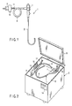
- FIG. 1 schematically shows an endoscope 1.
- FIG. 2 shows an endoscope cleaning apparatus 2 for cleaning the endoscope 1.
- FIG. 3 shows an endoscope sterilizing apparatus 3 for sterilizing the endoscope 1.
- FIG. 4 schematically shows an endoscopy system 4.
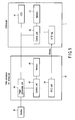
- FIG. 5 is a block diagram of the endoscopy system 4, and
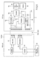
- FIG. 6 is a circuit diagram of an RFID unit and an RFID tag.
- the endoscope 1 includes an insertion section 6, an operation section 7 and a light guide cable 8.
- a connector 9 is provided at an extension end of the light guide cable 8.
- a communication connector section 10 for electrical connection to a peripheral device (not shown) is provided in the vicinity of the connector 9.
- the communication connector section 10 is provided with a connector portion for leakage testing (not shown).
- the communication connector 10 is equipped with a waterproof cap (not shown) that covers an exposed part of an electrical connection portion of the communication connector 10. When the endoscope 1 is cleaned and sterilized, the waterproof cap (not shown) prevents entrance of liquid such as a detergent or a disinfectant and protects the endoscope 1.
- An RFID tag 11 is provided at a position on the light guide cable 8 near the connector 9.
- the RFID tag 11 executes data transmission/reception in a non-electrical-contact method with an RFID unit (to be described later) that is provided on another apparatus such as the endoscope video processor, endoscope cleaning apparatus 2 or endoscope sterilizing apparatus 3.
- the RFID tag 11 includes a CPU (Central Processing Unit), a transmission/reception circuit, an antenna and a memory.
- CPU Central Processing Unit
- the basic principle of the non-electrical-contact method is a communication system using RFID (radio frequency identification) that uses radio waves.
- RFID radio frequency identification
- Examples of the RFID include “electromagnetic coupling method”, “capacitive coupling method”, “electromagnetic induction method”, “microwave method” and “optical communication method.”
- RFID is applicable not only to data transmission/reception but also to power transmission/reception.
- the memory (characteristic information recording section) of the RFID tag 11 stores characteristic information that includes history information as to whether the cleaning of the endoscope 1 that is to be sterilized is completed, as to when the cleaning process was executed, as to the result of leakage testing, as to whether sterilization is completed, and as to when sterilization was performed.
- the characteristic information includes information relating to the model name, i.e., type, of the endoscope 1, the product serial number of the endoscope 1, the time when an endoscopic inspection was conducted, and the case of treatment for which the endoscope 1 was used.
- An RFID system (wireless automatic recognition system) is constituted by the RFID tag 11 of the endoscope 1 and an RFID unit that is included in each of the endoscope video processor 32, endoscope cleaning apparatus 2 and endoscope sterilizing apparatus 3, which are described later. Information transmission/reception and power supply are executed through the communication using the RFID system.
- the RFID system adopts a wireless communication method using high-frequency waves, and not a wired method using electrical contact. Thus, both the RFID tag 11 and RFID unit can be sealed with members of a resin, etc., and both the RFID tag 11 and RFID unit have complete waterproof structures.
- the endoscope cleaning apparatus 2 shown in FIG. 2 comprises a cleaning bath 12 that accommodates the endoscope 1 as a medical instrument to be cleaned, a top cover 13, and a control panel 14 that sets sterilization process conditions such as a process step program.
- the RFID unit 15 is provided on a part of the cleaning bath 12.
- the RFID unit 15 constitutes an information reading unit that executes communication with the RFID tag 11 of the endoscope 1 that is accommodated in the cleaning bath 12, and reads record information in the RFID tag 11 that stores information such as the model name, product serial number, history, etc. of the endoscope 1.
- the endoscope cleaning apparatus 2 includes cleaning process condition setting means (step condition calculating section) that sets process conditions for cleaning the endoscope 1 accommodated in the cleaning bath 12, on the basis of the information of the endoscope 1 that is read out of the endoscope 1 accommodated in the cleaning bath 12.
- the RFID unit 15 is composed of a transmission/reception circuit, an antenna, etc., and is controlled by a control unit that is built in the endoscope cleaning apparatus 2.
- the endoscope 1 When the endoscope 1 is cleaned by the endoscope cleaning apparatus 2, the endoscope 1 is set in the cleaning bath 12, as shown in FIG. 2.
- Endoscope channel cleaning tubes 16 are connected to the endoscope 1 in order to clean the channels in the endoscope 1.
- a detergent is fed into the channels of the endoscope 1 through the cleaning tubes 16 from the endoscope cleaning apparatus 2 side. Thereby, the inside of each channel of the endoscope can be cleaned.
- a leak test tube 17 is connected to the connector portion for leakage testing in order to perform a leak test step for confirming that the outer member of the endoscope 1 has no hole or flaw.
- the leak test tube 17 communicates with the inside of the endoscope 1.
- a leak test step is started. Air is fed into the endoscope 1 through the leak test tube 17 from the endoscope cleaning apparatus 2. An air feed pressure at this time is measured by a leak sensor. If there is no hole or flaw in the endoscope 1, the air that is fed into the endoscope 1 does not leak, and a predetermined pressure value is indicated. If leakage occurs, the pressure value decreases and a leak portion of the endoscope 1 is detected. In this manner, it can be confirmed whether there is a hole or flaw in the endoscope 1.
- the endoscope sterilizing apparatus 3 includes a chamber (containing section) 21 for accommodating the endoscope 1 to be sterilized.
- An RFID unit 22 is provided on a part of the chamber 21.
- the RFID unit 22 is composed of a transmission/reception circuit, an antenna, etc.
- the RFID unit 22 is controlled by a control unit in the endoscope sterilizing apparatus 3.
- the RFID unit 22 executes wireless communication with the RFID tag 11 of the endoscope 1 and constitutes communication means for reading record information of the RFID tag 11 that stores information such as the model name, product serial number, history, etc. of the endoscope 1 accommodated in the chamber 21.
- the RFID unit 22 constitutes sterilization process condition setting means for setting process conditions for sterilizing the endoscope I accommodated in the chamber 21, on the basis of the characteristic information of the endoscope 1 that is read out of the endoscope 1 accommodated in the chamber 21 of the endoscope sterilizing apparatus 3.
- a cover 23 is provided on the inlet of the chamber 21.
- a control panel 24 is provided on the front surface of the endoscope sterilizing apparatus 3. Sterilization process conditions can be set through the control panel 24.
- FIG. 4 schematically shows the endoscopy system 4.
- the endoscopy system 4 includes a light source device 31, a video processor 32 and a monitor 33.
- the video processor 32 is provided with an RFID unit 34.
- the RFID unit 34 is controlled by a control unit that is provided in the video processor 32.
- the RFID unit 34 executes wireless communication with the RFID tag 11 of the endoscope 1.
- FIG. 5 is a block diagram of the endoscopy system 4.
- the endoscope 1 includes a CCD 41, a control unit 42 and a memory 43.
- the endoscope 1 includes the above-described RFID tag 11.
- the video processor 32 for the endoscope includes an image processing unit 44, a control unit 45 and a memory 46.
- the video processor 32 includes the above-described RFID unit 34.
- a video signal that is obtained by the CCD 41 of the endoscope 1 is sent to the image processing unit 44 of the video processor 32.
- the video signal is converted to an image signal by the image processing unit 44.
- the image signal is sent to the monitor 33, and the monitor 33 that serves as indication means displays an image.
- Wireless communication is executed by the RFID system between the endoscope 1 and video processor 32.
- Wireless communication is executed between the RFID tag 11 of endoscope 1 and the RFID unit 34.
- the cleaning information and sterilization information of the endoscope 1 and the characteristic information of the model number, etc. of the endoscope 1 are read in from the RFID tag 11.
- the information relating to the content of endoscopy, etc. is written in the RFID tag 11.
- FIG. 6 shows circuit configurations of the RFID unit 15, 22, 34 and the RFID tag 11.
- the RFID units 15, 22 and 34 are provided on the cleaning apparatus 2, sterilizing apparatus 3 and video processor 32, respectively.
- Each of the RFID unit 15, 22 and 34 comprises a transmission unit, a receiving unit, and a controller 54.
- the transmission unit includes a modulation circuit 52 having an oscillation circuit 51 for transmission, and a transmission coil L1.
- the receiving unit that includes a receiving coil L2 and a demodulation circuit 53.
- the controller 54 controls the transmission/reception by these units.
- the controller 54 is connected to a main-body control circuit 50 that is provided in the apparatus main body.
- the RFID tag 11 of the endoscope 1 comprises a coil L3 for signal transmission/reception, a capacitor C for oscillation, a demodulation circuit 55, a converter 56, a modulator 57, a main control unit 58 for controlling the respective components, and a memory 59.
- the RFID tag 11 includes a power supply circuit 60 that smoothes/rectifies a signal, which is received by a coil L4, and produces a stabilized drive power. The respective components are driven by the power produced by the power supply circuit 60.
- the endoscope 1 is set in the endoscope cleaning apparatus 2, and a leak test process is executed to confirm whether there is a hole or a flaw in the endoscope 1. If a flaw in the endoscope 1 is detected in the test, an alarm is issued to the user and the user is prompted to immediately repair the endoscope 1. It is better to also perform a channel clogging detection step for confirming whether the endoscope channel is clogged.
- the cleaning process for the endoscope 1 is started after confirming that there is no flaw in the endoscope 1 and no problem would arise even if the endoscope 1 is immersed in washing water.
- the endoscope cleaning apparatus 2 activates the RFID unit 15 and executes communication with the RFID tag 11 of the endoscope 1. Cleaning information as to when the cleaning of the endoscope 1 was performed and as to the result of the leak test step is written in the RFID tag 11 of the endoscope 1.
- the coil L1 is supplied with a radio-frequency wireless signal that is digitally modulated according to a write command, which is transferred as a serial signal from the controller 54 under the control of the main-body control circuit 50 of the endoscope cleaning apparatus 2.
- the coil L3 receives the wireless signal that is sent from the coil L1 of the RFID unit 15.
- a signal that is induced by the wireless signal is amplified and demodulated into the original digital signal in the demodulation circuit 55.
- the main control unit 58 writes information in the memory 59. In this way, communication is executed between the RFID tag 11 and RFID unit 15, and information is stored in the memory 59 in the RFID tag 11 of the endoscope 1.
- the endoscope 1 After the endoscope 1 is cleaned, the endoscope 1 is set in the chamber 21 of the sterilizing apparatus 3, and the sterilizing process for the endoscope 1 is executed.
- the sterilizing apparatus 3 communicates with the endoscope 1 and confirms the cleaning information and the model number of the endoscope 1, which is stored in the RFID tag 11 of the endoscope 1.
- the coil L1 is supplied with a radio-frequency wireless signal that is digitally modulated according to a read command, which is transferred as a serial signal from the controller 54 under the control of the main-body control circuit 50 of the sterilizing apparatus 3.
- a signal that is induced in the coil L3 is amplified and demodulated into the original digital signal in the demodulation circuit 55.
- the main control unit 58 of the RFID tag 11 reads in data from the memory 59, and converts the data to a serial signal in sync with a non-modulated signal sent from the coil L1.
- the modulation circuit 57 executes a control as to whether a tank circuit of the coil L3 and capacitor C is set in a resonant state.
- the controller 54 in the RFID unit 22 detects, through the coil L2, whether the tank circuit in the RFID tag 11 resonates. Thereby, communication of information is executed. In this way, communication is executed between the RFID tag 11 and RFID unit 22, and information is read out of the memory 59 in the RFID tag 11 of the endoscope 1.
- the sterilizing apparatus 3 does not start the sterilizing process operation and issues an alarm to the user to confirm these matters.
- the sterilizing process operation is started.
- the contents of the sterilization process conditions are automatically set on the basis of the information of the model number, etc. of the endoscope 1. For example, in the case of a long endoscope for colonoscopy or an endoscope with a very thin channel such as a forceps-raising wire guide, a long time is needed until steam for sterilization reaches all parts of the channel. Thus, the process time is set to be long. On the other hand, in the case of an endoscope with a simple channel structure or an endoscope with a short channel, the process time is set to be short.
- the sterilization steam temperature and pressure are increased and the process time is set to be short.
- the sterilizing process conditions can also be set in accordance with the information relating to the history of use of the endoscope 1 or the history of cleaning/sterilization.
- the sterilizing process is executed on the basis of the content of the sterilizing process that is properly set according to the endoscope 1 to be sterilized.
- the sterilizing apparatus 3 executes communication with the endoscope 1 once again and stores sterilization information, which relates to the time and kind of the sterilizing process, into the memory 59 in the RFID tag 11 of the endoscope 1.
- the endoscope 1 is connected to the light source device 31 and video processor 32, as shown in FIG. 4.
- the video processor 32 communicates with the connected endoscope 1 and confirms the sterilization information. If it is confirmed that the endoscope 1 is a sterilized one, the sterilization information as to what kind of sterilizing process was executed and when it was done is displayed on the monitor 33, and the user is prompted to confirm the information. If it is determined that the endoscope 1 is not a sterilized one, the monitor 33 displays a corresponding alarm message to the user.
- the video processor 32 confirms the sterilizing process content and estimates the temperature of the CCD 41 of the endoscope 1.
- the video processor 32 prestores data relating to a temperature decrease of the CCD 41 of the endoscope 1 in the case where the endoscope 1 is sterilized and then left in the natural state.
- the video processor 32 recognizes an elapsed time from the completion of the sterilizing process and thus calculates the temperature of the CCD 41.
- a filtration constant for removing noise due to the heat of the CCD 41 is calculated on the basis of the temperature of the CCD 41. Thereby, correction of the endoscopic image is automatically executed.
- the endoscope 1 can continuously be used without waiting for a long time until the CCD 41 in the endoscope 1 is completely cooled down.
- the video processor, cleaning apparatus and sterilizing apparatus for the endoscope are configured to be able to write, by communication, the cleaning information and sterilization information in the memory in the endoscope, and to read out information from the memory. Based on the information, the process conditions are automatically set or corrected. Thereby, the load on a user is reduced, and the exact and quick process can be executed.
- the cleaning apparatus communicates with the endoscope and receives information relating to the endoscope.
- the cleaning apparatus stores information relating to the cleaning in the memory means of the endoscope 1.
- the information relating to the cleaning refers to, for instance, information as to when the cleaning process was executed, information as to what kind of cleaning process was executed, information relating to the result of a leak test step for confirming whether leakage occurs in the endoscope, and information relating to the result of a channel clogging detection step for confirming whether the endoscope channel is clogged.
- the endoscope sterilizing apparatus communicates with the endoscope and acquires information relating to the cleaning and information relating to the endoscope itself, which are stored in the endoscope. Based on the information, the endoscope sterilizing apparatus confirms whether the endoscope 1 has exactly been cleaned. In addition, the endoscope sterilizing apparatus confirms whether the endoscope is free from leakage or channel clogging. If it is not possible to confirm such information, an alarm may be issued to the user to prevent the sterilizing process from being started.
- the conditions for the sterilizing process are automatically set in accordance with the type of the endoscope.
- the endoscope sterilizing apparatus 3 executes communication with the endoscope 1 once again and stores the information relating to sterilization in the endoscope.
- the information relating to sterilization refers to, for instance, information as to what kind of sterilizing process was executed and when the sterilizing process as executed.
- the endoscope image processing apparatus communicates with the endoscope and acquires information relating to the sterilization. Based on the information as to what kind of sterilizing process was executed and when the sterilizing process as executed, the endoscope image processing apparatus estimates the temperature in the inside of the endoscope and executes, for example, a noise-reduction image process in accordance with the temperature characteristics of the CCD.
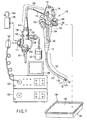
- FIG. 7 is an explanatory view that schematically shows the structure of an endoscope.
- FIG. 8 is an explanatory view that schematically shows the structure of an autoclave apparatus for sterilizing the endoscope shown in FIG. 7.
- FIG. 9 is a time chart of an autoclave sterilization process using the autoclave apparatus shown in FIG. 8.
- FIG. 10 is a flow chart that illustrates the autoclave sterilization process by the autoclave apparatus shown in FIG. 8.
- an endoscope apparatus 101 includes an endoscope 102 with imaging means; a light source device 103 that is detachably connected to the endoscope 102 and supplies illumination light to a light guide (not shown) that is provided on the endoscope 102; a video processor 105 that is connected to the endoscope 102 via a signal cable 104, controls the imaging means of the endoscope 102, and processes a video signal obtained by the imaging means; and a monitor 106 that displays a video image corresponding to a subject image, which is output from the video processor 105.
- the endoscope 102 is formed such that the endoscope 102 can be subjected to a cleaning process after it is used for observation or treatment, and the endoscope 102, which has been subjected to the cleaning process, can subsequently be subjected to a sterilizing process using high-pressure steam.
- the endoscope 102 includes a flexible thin, long insertion section 107; an operation section 108 that is connected to a proximal end side of the insertion section 107; a flexible connection cord 109 that extends from a side part of the operation section 108; and a connection section 110 that is provided at an extension end of the connection cord 109 and is detachably connected to the light source device 103.
- a side part of the connector section 110 is provided with an electric connector section 111 that is detachably connectable to the signal cable 104 connected to the video processor 105.
- the electric connector section 111 is provided with an air passage portion (not shown) for communication between the inside of the endoscope 102 and the outside.
- connection part between the insertion section 107 and the operation section 108 is provided with an insertion-section-side breakage-preventing member 112 that has an elastic member for preventing sharp bending of the connection part.
- a connection part between the operation section 108 and connection cord 109 is provided with an operation-section-side breakage-preventing member 113.
- a connector-section-side breakage-preventing member 114 is provided at a connection part between the connection cord 109 and connection section 110.
- the insertion section 107 comprises a soft, flexible tube portion 115; a bendable portion 116 that is provided at a distal end side of the flexible tube portion 115 and can be bent by the operation of the operation section 108; and a distal end portion 117 that is provided at a distal end of the flexible tube portion 115 and is provided with an observation optical system and an illumination optical system (not shown).
- the distal end portion 117 of the insertion section 107 is provided with an air-feeding/water-feeding nozzle 118 for feeding a detergent or gas toward an optical member that is provided on the outer surface of the observation optical system (not shown) by an air-feeding operation and a water-feeding operation; a suction portion 119 that is a distal-end-side opening of an instrument channel (not shown) for insertion of an instrument provided in the insertion section 107 or for suction of liquid in a body cavity; and a liquid-feeding port 120 that is open to an object of observation and feeds liquid.
- the connector section 110 is provided with a gas-feeding mouthpiece 121 that is detachably connected to a gas supply source (not shown) that is built in the light source device 103; a water-feeding tank pressurizing mouthpiece 123 and a liquid supply mouthpiece 124, which are detachably connected to a water-feeding tank 122 that is a liquid supply source; a suction mouthpiece 125 that is connected to a suction source (not shown) for effecting suction from the suction port 119; and an injection mouthpiece 126 that is connected to water-feeding means (not shown) for feeding water from the liquid-feeding port 120.
- the connector section 110 is provided with a ground terminal mouthpiece 127 for feeding leak current back to a high-frequency treatment device when high-frequency leak current occurs in the endoscope in the case of conducting high-frequency treatment, etc.
- the operation section 108 is provided with an air-feed/water-feed operation button 128 for executing an air-feed operation and a water-feed operation; a suction operation button 129 for executing a suction operation; a bending operation knob 130 for executing a bending operation of the bendable portion; a plurality of remote switches 131 for remote-controlling the video processor 105; and an instrument insertion port 132 that is an opening communicating with the instrument channel.
- a watertight cap 133 with a pressure adjusting valve is detachably connectable to the electric connector section 111 of the endoscope 102.
- the watertight cap 133 is equipped with a pressure adjusting valve 133a.
- a sterilization case 134 for storing the endoscope 102 is used.
- the sterilization case 134 as shown in FIG. 7, comprises a tray 135 and a cover member 136.
- the tray 135 and cover member 136 are provided with a plurality of air passage holes (not shown). Steam can pass through the air passage holes.
- the connector section 110 is provided with a restriction member (not shown) that corresponds to the shape of the endoscope 102.
- the restriction member is formed such that the respective parts of the endoscope 102 are placed at predetermined positions.
- the restriction member is provided with an insertion section restriction portion (not shown) in which the elongated flexible section 107 is stored.
- Typical conditions for high-pressure steam sterilization are U.S. standards ANSI/AAMI ST37-1992, which are endorsed by American National Standards Institute and issued by Association for the Advancement of Medical Instrumentation. According to these standards, in the case of the pre-vacuum type, the time for a sterilization step is four minutes at 132°C. In the case of the gravity type, the time for a sterilization step is 10 minutes at 132°C.
- the temperature condition for the sterilization step with high-pressure steam is generally set in the range of about 115°C to 138°C, although the temperatures vary depending on the type of the high-pressure steam sterilizing apparatus and the time of the sterilization step. In some types of sterilizing apparatuses, the temperature can be set at about 142°C.
- the time condition varies depending on the temperature condition for the sterilization step. In general, the time is set between about 3 minutes and 60 minutes. In some types of sterilizing apparatuses, the time can be set at about 100 minutes. In this step, the pressure in the sterilization chamber is generally set at about +0.2 MPa, relative to the atmospheric pressure.
- the high-pressure steam sterilization step for the general pre-vacuum type includes a pre-vacuum step for setting the sterilization chamber, where the to-be-sterilized apparatus is accommodated, in a vacuum state prior to sterilization, and a subsequent sterilization step for feeding high-pressure, high-temperature steam into the sterilization chamber and executing sterilization.
- the pre-vacuum step is a step for making the steam reach minute portions of the to-be-sterilized apparatus in the subsequent sterilization step.
- the pressure in the sterilization chamber is reduced so that high-pressure, high-temperature steam may reach every part of the to-be-sterilized apparatus.
- the pressure in the sterilization chamber in the pre-vacuum step is generally set at about -0.07 MPa to -0.09 MPa, relative to the atmospheric pressure.
- the sterilization step is followed by a drying step for setting the inside of the sterilization chamber in a reduced-pressure state once again, thereby to dry the sterilized apparatus.
- the sterilization chamber is decompressed to remove steam from the sterilization chamber. This facilitates the drying of the to-be-sterilized apparatus in the sterilization chamber.
- the pressure in the drying sterilization chamber in the drying step is generally set at about -0.07 MPa to -0.09 MPa, relative to the atmospheric pressure.
- the sterilization is performed in the state in which the watertight cap 133 with the pressure adjusting valve is attached to the electric connector section 111.
- the pressure adjusting valve 133a of the watertight cap 133 is closed, and the passage hole is closed by the watertight cap 133.
- the inside of the endoscope 102 is watertightly sealed from the outside.
- the pressure in the sterilization chamber is reduced in the pre-vacuum step, and such a pressure difference occurs that the outside pressure becomes lower than the inside pressure of the endoscope 102.
- the pressure adjusting valve 133a is opened and the inside and outside of the endoscope 102 communicate via the air passage hole. This prevents the occurrence of a large pressure difference between the inside of the endoscope 102 and the inside of the sterilization chamber. Hence, when the endoscope is subjected to the sterilizing process, no damage occurs due to the pressure difference between the inside and outside.
- the pressure adjusting valve 133a is closed.
- high-pressure, high-temperature steam does not positively enter the endoscope 102 via the watertight cap 133 and air passage hole.
- high-temperature, high-pressure steam gradually enters the endoscope 102 through, for example, the outer sheath of the flexible tube formed of high-polymer material or an O-ring formed of fluoro-rubber, silicone rubber, etc., which is a sealing means provided at a connection part of the outer member of the endoscope 102.
- a pressure acting from outside toward inside which is a sum of the reduced pressure in the pre-vacuum step and the applied pressure in the sterilization step, is applied to the outer member of the endoscope 102.
- a pressure acting inward from outside which corresponds to the reduced pressure in the pressure-reducing step, is applied to the outer member of the endoscope 102. If the watertight cap 133 is removed from the electric connector section 111, the inside and outside of the endoscope 102 communicate through the air passage hole and the inside pressure of the endoscope 102 changes to the atmospheric pressure. As a result, the pressure load on the outer member of the endoscope 102 is eliminated.
- a chamber 141 for accommodating the endoscope 102 and executing an autoclave process is formed in an autoclave apparatus 140.
- the autoclave apparatus 140 includes a water tank, a steam generating device and a suction pump, which are not shown.
- the autoclave apparatus 140 includes a process step selection section 142, a process step display section 143, an endoscope data reading device 144, and an endoscope data display section 145.
- the autoclave apparatus 140 also includes a write control section 125 that executes a control to write an executed treatment process condition, as history information, in the memory section of the endoscope 102; a step condition calculation section 126 that calculates a sterilization process condition relating to the step; and a control section 128.
- the control section 128 controls the sterilization step of the autoclave apparatus 140 in accordance with the sterilization process condition that is set by the step condition calculation section 126.
- the process step selection section 142 is provided with a plurality of operation buttons of A, B and C. Needless to say, the number of buttons may be four or more, or two.
- the endoscope data reading device 144 shown in FIG. 8 is detachably connectable to the electric connector section 111 of the endoscope 102.
- the endoscope data reading device 144 is connected to the autoclave apparatus 140 by means of a soft communication cord 144a.
- the connector section 110 incorporates a memory unit 146 that stores endoscope data. If the endoscope data reading device 144 is connected to the electric connector section 111, the autoclave apparatus 140 is enabled to read the data stored in the memory unit 146.
- the endoscope data reading device 144 can write executed process content, as history information, in the memory unit 146 of the to-be-processed endoscope 102.
- the endoscope data reading device 144 functions both as an apparatus for reading data and as an apparatus for writing data.
- Data may be written to and read from the memory unit 146 of the autoclave apparatus 140 by means of data transmission/reception using a non-electric-contact communication method, without using the apparatus 144 with the soft cord 144a.
- RFID radio frequency identification
- Examples of the RFID include “electromagnetic coupling method”, “capacitive coupling method”, “electromagnetic induction method”, “microwave method” and “optical communication method.” This method is applicable not only to data transmission/reception but also to power transmission/reception.
- FIG. 9 illustrates, in a simplified fashion, the autoclave sterilization step that is executed by the autoclave apparatus 140.
- a single autoclave sterilization process comprises a pre-vacuum step (PV step) for setting the inside of the chamber 141 in a negative-pressure state, a high-pressure steam sterilization step (S step) and a negative-pressure drying step (D step).
- PV step pre-vacuum step
- S step high-pressure steam sterilization step
- D step negative-pressure drying step
- a negative pressure is built, following which steam is injected. Thereby, steam can be sufficiently fed to thin channels in the endoscope 102.
- the inside of the endoscope 102 tries to have a higher pressure than the inside of the chamber 141.
- the pressure in the endoscope 102 is kept at a level close to the pressure in the chamber 141 by the function of the pressure adjusting valve 33a of the watertight cap 133.
- the temperature reaches a sterilization temperature of, e.g. 135°C.
- a small amount of steam enters the endoscope 102 via the soft flexible tube portion 115 or soft sealing portions at some locations (the outside pressure (i.e. pressure in the chamber 141) is much higher than the inside pressure of the endoscope 102).
- the inside of the chamber 141 is dried with hot air while the inside of the chamber 141 is kept at a negative pressure.
- the pressure adjusting valve 133a functions and most of the steam, which has entered the endoscope 102 in the S step, can be removed.
- FIG. 10 illustrates process steps relating to the handling of the data stored in the memory unit 146 of the endoscope 102. The flow of the process, as well as these steps, is described.
- step S1 of "read characteristic data of the endoscope” the watertight cap 133 of the cleaned endoscope 102 is once removed, and the endoscope data reading device 144 is connected to the electric connector section 111. Then, the autoclave apparatus 140 reads the information that is stored in the memory unit 146 of the endoscope 102.
- the information includes history information relating to, e.g. the PV step time and negative-pressure level, the S step time and temperature, and D step time and negative-pressure level in the previously executed autoclave processes.
- the history information which relates to, e.g. previous ten steps, may be displayed on the endoscope data display section 145.
- the information that is stored in the memory unit 146 may include information such as the model type of the endoscope 102, other than the history information.
- step S2 of "calculate a recommendable autoclave step” the autoclave apparatus 140 calculates, based on the read data, a recommendable step as an autoclave step that is next executed. For example, if it is determined that the previous D step time was shorter than a proper time, a step in which the D step time is relatively long is recommended.
- step S3 of "display a recommendable step” the content of the recommendable step is displayed on the process step display section 143, thus informing the user.
- the endoscope 102 is placed in the chamber 141. Prior to this, the watertight cap 133 is attached to the electric connector section 111.
- buttons on the process step selection section 142 designate three autoclave step patterns A, B and C.
- pattern A is most suitable to the endoscope 102, but the D step time is long.
- Pattern B is usable when a relatively quick process is required, and thus the D step time is relatively short.
- Pattern C relates to a process of autoclaving an instrument such as an accessory, a cleaning instrument or a treatment instrument, which has a simpler structure than the endoscope 102.
- both the PV step time and D step time are very short. That is, all the steps of the autoclave process can be completed in a very short time period.
- Pattern C is applicable to the endoscope 102 when a quick process is particularly required.
- the D step time is very short, the application of pattern C to the endoscope 102 leads to accumulation of moisture in the endoscope 102, degrading the durability of the endoscope 102.
- step S4 of "user setting/input” if pattern A was previously applied to the endoscope 102 in succession, the process step display section 143 displays a message to the effect that any one of patterns A to C is applicable. If a quick process is needed, the user can select pattern C.
- the autoclave apparatus 140 that reads the associated data causes the display section 143 to display a message to the effect that pattern A is recommendable.
- the autoclave apparatus 140 may be configured to become inoperable if the user presses buttons other than the button A.
- step S5 of "execute an autoclave step” is performed and the autoclave operation is started.
- step S6 of "write step result information in the endoscope” is executed.
- the endoscope 102 is taken out of the chamber 141, and the watertight cap 133 is removed from the electric connector section 111.
- the endoscope data reading device 144 is connected to the electric connector section 111 once again.
- the executed process content is written as history information in the memory unit 146 of the endoscope 102 that is the object of processing.
- the data relating to the autoclave process which is executed each time, is managed for each endoscope. Based on the data, an autoclave process that is next executed is determined. Thereby, the durability of the endoscope 102 is secured.
- the D step is an important step for minimizing the moisture in the endoscope 102. If the user desires a quick process and the D step time becomes inadequate, the durability of the endoscope 102 is seriously affected.
- this embodiment may adopt such management that the number of times and the frequency of execution of the process with the above-mentioned special condition are recorded, and the same endoscope is prevented from being subjected to the process many times.
- the patterns A, B and C of the autoclave process may be associated with displays that recommend applicable products such as “flexible endoscope”, “rigid endoscope” and “forceps”. Further, buttons, which are indicative of “flexible endoscope”, “rigid endoscope”, “forceps” and “linen”, may be provided. If the objects that are placed in the chamber 41 are a forceps and linen, the user may press the buttons indicative of "forceps" and "linen”. Then, the autoclave apparatus 40 executes calculations and determines a process that is suitable for autoclaving the two objects, and automatically operates.
- the user can select the autoclave process in accordance with the need at each time, and the durability of the endoscope can be secured.
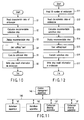
- FIG. 11 is an explanatory view that shows the structure of the autoclave apparatus that subjects the endoscope to autoclave-sterilization.
- FIG. 12 is a flow chart illustrating the flow of the autoclave process using the autoclave apparatus shown in FIG. 11.
- an autoclave apparatus 140 and an endoscope cleaning apparatus 147 are connected to a central management apparatus 148 by a signal line 149. Specifically, the autoclave apparatus 140 itself does not execute data management and processing. The data management and processing are executed by the central management apparatus 148. As is shown in FIG. 11, a plurality of autoclave apparatuses 140 and a plurality of endoscope cleaning apparatuses 147 may be provided. In this case, too, the data management/processing is executed by the common central management apparatus 148. In the other structural aspects, the present embodiment is the same as the second embodiment.
- step S11 the endoscope data reading device 144 is connected to the electric connector section 111 before the endoscope 102 is placed in the chamber 141.
- the central management apparatus 148 reads out the ID number of the endoscope from the memory unit 146.
- the central management apparatus 148 stores past records relating to the ID number.
- the central management apparatus 148 reads out the data that relates to, for instance, the PV step time and negative-pressure level, the S step time and temperature and the D step time and negative-pressure level in the previously executed autoclave step. Then, the central management apparatus 48 executes the process of "calculate a recommendable autoclave step" in step S13.
- step S14 information relating to a recommendable process is sent to the autoclave apparatus 140 and the process step display section 143 is caused to display the information, thereby notifying the user.
- step S15 the user sets (inputs) the process to be executed.
- one of the buttons on the process step selection section 142 is selected.
- the process step selection section 142 may be composed of a touch panel such that the user can freely input, e.g. the D step time in units of a minute. If the input content differs from the recommendable process content that is displayed on the process step display section 143, the central management apparatus 148 may execute determination and may effect alarm display on the process step display section 143. In addition, the central management apparatus 148 may control the autoclave apparatus 140 so as to prohibit the operation of the autoclave apparatus 140.
- step S16 the autoclave sterilization is executed. If the sterilization is completed, the information relating to the executed process is sent to the central management apparatus 148 in step S17 and is stored in the memory unit as the information associated with the ID number.
- Information of the temperature sensor and pressure sensor that are provided in the chamber 141 may be recorded as management information as to whether the autoclave apparatus 140 has normally operated in fact. If abnormality occurs, the central management apparatus 148 executes a control to suspend the process and to effect display on the process step display section 143 to prompt the user to perform a check.
- the chamber 141 may be provided with a sound sensor to sense burst sound.
- the endoscope 102 is cleaned by the endoscope cleaning apparatus 147 before executing autoclave sterilization.
- the endoscope cleaning apparatus 147 may also be provided with the endoscope data reading device 144 and the central management apparatus 148 may manage the information as to what kind of cleaning was done.
- the central management apparatus 148 may be connected to the video processor 105. If the user connects the signal cable 104 to the electric connector section 111 at the time of an inspection, it becomes possible to quickly and exactly understand whether the endoscope has normally been cleaned/sterilized.
- the common central management apparatus 148 can manage/control the plural endoscopes 102, endoscope cleaning apparatuses 147 and autoclave apparatuses 140. Therefore, the structure of the memory unit 146 can be made simpler, and the computers (information processing units, control units) in the autoclave apparatus 140 and endoscope cleaning apparatus 147 can be dispensed with. In particular, in a large-scale hospital, it becomes possible to comprehensively secure the exact information management and the durability of endoscopes at a minimum cost.
- an efficient system can be provided in the case where a plurality of autoclave apparatuses 140 are employed.
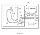
- FIG. 13 is an explanatory view that schematically shows the structure of an autoclave apparatus for autoclaving the endoscope 102 in the state in which the endoscope 102 is placed in the chamber 141.
- an endoscope connection section 150 which is provided on the autoclave apparatus 140 and is substituted for the above-described watertight cap 133, is connected to the electric connector section 111.
- a control unit 151 of the autoclave apparatus 140 is rendered communicable with the memory unit 146.
- the inside of the endoscope 102 communicates with a conduit 152.
- the conduit 152 communicates with the outside of the autoclave apparatus 140 via a control valve 153.
- a conduit 154 communicates with the chamber 141 and reaches a control valve 156 via a filter 155 that blocks passage of micro-organisms.
- the control valve 153 communicates with the control valve 156 via a conduit 157.
- the control unit 151 controls the control valve 153, control valve 156, suction pump 158 and the steam generating device (not shown).
- the present embodiment is the same as the second embodiment.
- the conduit connection section 150 is connected to the watertight cap 111. Thereby, like the second embodiment, information is read out of the memory unit 146 and the control unit 151 executes processing.
- a variation in pressure in the chamber 141 of the autoclave process is controlled in the following manner. For example, when the chamber 141 is set at a negative pressure by the suction pump 158, the control valve 153 equalizes the pressures in the endoscope 102 and to the pressure in the chamber 141. (That is, the inside of the endoscope 102 is also set at a negative pressure by the suction pump 158.)
- the control valve 153 is controlled to eliminate moisture in the endoscope 102 as quickly as possible.
- the inside of the endoscope 102 is sucked by the suction pump 158 and set at a negative pressure level.
- a suction device for sucking an inside gas in the endoscope 102 is constituted.
- air is let into the endoscope 102 from the outside of the autoclave apparatus 140.
- An injection device, which injects a gas different from the gas in the endoscope into the endoscope 102 after the suction, is thus constituted.
- gas in the chamber 141 is drawn. Using the same means described above, ventilation may be achieved.
- gas in the chamber 141 may be fed into the endoscope 102 from the endoscope connection section 150 via the control valve 156 and control valve 153 and the gas in the endoscope 102 may be replaced with the air in the chamber 141. Outside air is not necessarily in a high-level dry state. In this way, ventilation in a high-level dry state can be executed by feeding the gas in the chamber 141, which is in the high-level dry state, into the endoscope 102.
- a cooling device may be provided at a given position on the conduit 152, and cool gas may be fed into the endoscope 102 to more quickly cool the endoscope 102.
- Ventction in the endoscope 102 can be executed using the suction pump 158 that is employed to control the pressure in the chamber 141. Therefore, there is no need to provide another pump for ventilation in the endoscope 102, and the cost is reduced.
- the suction pump 158 may be provided anywhere along the flow path of the conduit 152, control valve 153, conduit 157, control valve 156 and conduit 154. Using the suction pump 158, air may be fed from the outside of the autoclave apparatus 140 into the chamber 141 via the filter 155, thereby cooling the endoscope 102. In this case, it is preferable that the cooling step be executed after the drying step for drying the inside of the chamber 141. This can reduce the cooling time, without condensation.
- the inside of the endoscope can easily be ventilated, and the durability can be secured.
- the autoclave apparatus 140 may integrally be provided with the function of cleaning the endoscope 102. Thereby, the characteristic information relating to the cleaning/sterilization of the endoscope 102 can be managed with a single setting.
Landscapes
- Health & Medical Sciences (AREA)
- Life Sciences & Earth Sciences (AREA)
- Animal Behavior & Ethology (AREA)
- General Health & Medical Sciences (AREA)
- Public Health (AREA)
- Veterinary Medicine (AREA)
- Surgery (AREA)
- Epidemiology (AREA)
- Optics & Photonics (AREA)
- Nuclear Medicine, Radiotherapy & Molecular Imaging (AREA)
- Biophysics (AREA)
- Pathology (AREA)
- Radiology & Medical Imaging (AREA)
- Physics & Mathematics (AREA)
- Engineering & Computer Science (AREA)
- Biomedical Technology (AREA)
- Heart & Thoracic Surgery (AREA)
- Medical Informatics (AREA)
- Molecular Biology (AREA)
- Endoscopes (AREA)
- Apparatus For Disinfection Or Sterilisation (AREA)
Applications Claiming Priority (2)
| Application Number | Priority Date | Filing Date | Title |
|---|---|---|---|
| JP2001063705A JP3691764B2 (ja) | 2001-03-07 | 2001-03-07 | オートクレーブ装置 |
| PCT/JP2002/009063 WO2004022109A1 (fr) | 2001-03-07 | 2002-09-05 | Sterilisateur et procede de sterilisation |
Publications (3)
| Publication Number | Publication Date |
|---|---|
| EP1550465A1 true EP1550465A1 (fr) | 2005-07-06 |
| EP1550465A4 EP1550465A4 (fr) | 2005-09-07 |
| EP1550465B1 EP1550465B1 (fr) | 2013-05-22 |
Family
ID=32684056
Family Applications (1)
| Application Number | Title | Priority Date | Filing Date |
|---|---|---|---|
| EP02765427.6A Expired - Lifetime EP1550465B1 (fr) | 2001-03-07 | 2002-09-05 | Sterilisateur et procede de sterilisation |
Country Status (5)
| Country | Link |
|---|---|
| US (1) | US20050148819A1 (fr) |
| EP (1) | EP1550465B1 (fr) |
| JP (1) | JP3691764B2 (fr) |
| CN (1) | CN100369635C (fr) |
| WO (1) | WO2004022109A1 (fr) |
Cited By (13)
| Publication number | Priority date | Publication date | Assignee | Title |
|---|---|---|---|---|
| EP1600174A3 (fr) * | 2004-05-28 | 2006-03-01 | Ethicon, Inc. | Contrôle de cycle de stérilisation/désinfection |
| WO2007047404A2 (fr) | 2005-10-12 | 2007-04-26 | Volcano Corporation | Appareil et procédé d'utilisation d'intelligence relative à un cathéter rfid |
| EP1875856A4 (fr) * | 2005-04-25 | 2012-10-10 | Olympus Medical Systems Corp | Dispositif de nettoyage/desinfection d endoscope |
| WO2017032561A3 (fr) * | 2015-08-27 | 2017-07-06 | Olympus Winter & Ibe Gmbh | Dispositif de nettoyage et de désinfection, système médical et procédé pour faire fonctionner un dispositif de nettoyage et de désinfection |
| EP3431196A1 (fr) * | 2013-05-21 | 2019-01-23 | Smart Medical Systems Ltd. | Système et procédé de retraitement d'endoscope |
| US10398295B2 (en) | 2014-12-22 | 2019-09-03 | Smart Medical Systems Ltd. | Balloon endoscope reprocessing system and method |
| US10456564B2 (en) | 2011-03-07 | 2019-10-29 | Smart Medical Systems Ltd. | Balloon-equipped endoscopic devices and methods thereof |
| US10610086B2 (en) | 2010-03-09 | 2020-04-07 | Smart Medical Systems Ltd. | Balloon endoscope and methods of manufacture and use thereof |
| US10835107B2 (en) | 2015-04-03 | 2020-11-17 | Smart Medical Systems Ltd. | Endoscope electro-pneumatic adaptor |
| IT202000004852A1 (it) * | 2020-03-06 | 2021-09-06 | S I D E M S P A | Metodo per ricondizionare dispositivi medicali, relativo apparato e prodotto informatico. |
| WO2023283135A1 (fr) * | 2021-07-09 | 2023-01-12 | Dental Smartmirror, Inc. | Dispositif médical ayant une valve apte à l'autoclavage |
| IT202200004118A1 (it) * | 2022-03-04 | 2023-09-04 | S I D Em S P A | Metodo per ricondizionare dispositivi medicali, relativo apparato e prodotto informatico |
| IT202200004130A1 (it) * | 2022-03-04 | 2023-09-04 | S I D Em S P A | Metodo per ricondizionare dispositivi medicali, relativo apparato e prodotto informatico |
Families Citing this family (58)
| Publication number | Priority date | Publication date | Assignee | Title |
|---|---|---|---|---|
| JP3691764B2 (ja) * | 2001-03-07 | 2005-09-07 | オリンパス株式会社 | オートクレーブ装置 |
| WO2003047638A1 (fr) * | 2001-12-07 | 2003-06-12 | Olympus Optical Co., Ltd. | Systeme de sterilisation a la vapeur haute pression pour equipement medical et dispositif et procede de sterilisation de cet equipement |
| JP2005253790A (ja) * | 2004-03-12 | 2005-09-22 | Olympus Corp | オートクレーブ滅菌処理方法及びこの処理方法を適用するオートクレーブ滅菌装置 |
| JP2006051073A (ja) * | 2004-08-10 | 2006-02-23 | Olympus Corp | 内視鏡システム、情報処理装置、内視鏡装置、内視鏡洗滌装置及びプログラム |
| ES2552108T3 (es) * | 2005-03-11 | 2015-11-25 | Howard Florey Institute Pty Ltd | Compuestos flavonoides y usos de los mismos |
| US8388523B2 (en) | 2005-04-01 | 2013-03-05 | Welch Allyn, Inc. | Medical diagnostic instrument having portable illuminator |
| JP2009515561A (ja) | 2005-04-01 | 2009-04-16 | ウェルチ アレン インコーポレーテッド | 膣鏡器具とともに用いる照明アセンブリ |
| US20060252990A1 (en) * | 2005-05-06 | 2006-11-09 | Melissa Kubach | Systems and methods for endoscope integrity testing |
| US8109871B2 (en) | 2005-05-06 | 2012-02-07 | Minntech Corporation | Endoscope integrity tester including context-sensitive compensation and methods of context-sensitive integrity testing |
| US7340943B2 (en) * | 2005-09-30 | 2008-03-11 | Ethicon, Inc. | Method of detecting connection of test port on an endoscope |
| US7686761B2 (en) * | 2005-10-28 | 2010-03-30 | Ethicon, Inc. | Method of detecting proper connection of an endoscope to an endoscope processor |
| US7901349B2 (en) * | 2005-11-02 | 2011-03-08 | Minntech Corporation | Endoscope reprocessor connectivity apparatus and method |
| US20070160494A1 (en) * | 2006-01-06 | 2007-07-12 | Sands Daniel L | Autoclave system using rfid tags on a case and/or instruments |
| US8142352B2 (en) | 2006-04-03 | 2012-03-27 | Welch Allyn, Inc. | Vaginal speculum assembly having portable illuminator |
| US20070282165A1 (en) * | 2006-05-31 | 2007-12-06 | Karl Storz Endovision | Optically coupled endoscope with microchip |
| US7757543B2 (en) * | 2006-07-13 | 2010-07-20 | Advanced Cardiovascular Systems, Inc. | Radio frequency identification monitoring of stents |
| JP2008073182A (ja) * | 2006-09-20 | 2008-04-03 | Pentax Corp | 内視鏡、内視鏡管理システムおよび内視鏡管理方法 |
| JP5188800B2 (ja) * | 2007-12-21 | 2013-04-24 | オリンパスメディカルシステムズ株式会社 | 内視鏡洗浄消毒装置及びこの内視鏡洗浄消毒装置による漏水検知方法 |
| JP2009160249A (ja) * | 2008-01-08 | 2009-07-23 | Fujifilm Corp | 内視鏡洗浄滅菌装置、内視鏡洗浄滅菌システム、内視鏡洗浄滅菌方法 |
| JP2009160250A (ja) * | 2008-01-08 | 2009-07-23 | Fujifilm Corp | 内視鏡洗浄滅菌装置及び方法 |
| DE102008010948B4 (de) * | 2008-02-25 | 2013-10-17 | Fresenius Medical Care Deutschland Gmbh | Verfahren zum Kalibrieren eines Sensors innerhalb einer Kammer; Sensor, Disposable und Behandlungsvorrichtung mit einem solchen Sensor |
| ES2383425T3 (es) | 2008-07-16 | 2012-06-21 | Emd Millipore Corporation | Dispositivos farmacéuticos resistentes con SOI a altas temperaturas |
| US8648932B2 (en) | 2009-08-13 | 2014-02-11 | Olive Medical Corporation | System, apparatus and methods for providing a single use imaging device for sterile environments |
| JP5624745B2 (ja) * | 2009-10-23 | 2014-11-12 | オリンパス株式会社 | 内視鏡システム |
| CN101788222B (zh) * | 2010-01-14 | 2012-01-11 | 北京白象新技术有限公司 | 一种具有可追溯性的内窥镜干燥箱 |
| CN101785870B (zh) * | 2010-01-28 | 2012-11-21 | 北京白象新技术有限公司 | 一种具有可追溯性的清洗消毒器 |
| BR112012024237A2 (pt) | 2010-03-25 | 2019-05-28 | Olive Medical Corp | sistema e método para fornecer um dispositivo de imageamento de utilização única para aplicações medicas |
| US8673212B2 (en) * | 2010-05-28 | 2014-03-18 | Steris Corporation | Apparatus to decontaminate equipment containing internal channels |
| EP2708021B1 (fr) | 2011-05-12 | 2019-07-10 | DePuy Synthes Products, Inc. | Capteur d'images comportant des interconnexions d'optimisation de tolérance |
| WO2013021701A1 (fr) * | 2011-08-09 | 2013-02-14 | オリンパスメディカルシステムズ株式会社 | Dispositif de lavage et de stérilisation d'endoscopes |
| ITVI20110237A1 (it) * | 2011-08-31 | 2013-03-01 | I M S S R L | Macchina per la sanificazione a freddo di dispositivi medicali |
| CN102380114B (zh) * | 2011-11-14 | 2013-09-18 | 曲林 | 喉镜片消毒机 |
| ITMI20112334A1 (it) * | 2011-12-21 | 2013-06-22 | Absolute Up S R L | Sterilizzatrice a vapore |
| JP6000702B2 (ja) * | 2012-07-12 | 2016-10-05 | オリンパス株式会社 | 医療システム |
| EP2877079B1 (fr) | 2012-07-26 | 2021-04-21 | DePuy Synthes Products, Inc. | Système de caméra à capteur d'image cmos monolithique à surface minimale |
| CA2880536C (fr) | 2012-08-01 | 2020-08-25 | The United States Of America As Represented By The Department Of Veterans Affairs | Procedes d'organisation de desinfection d'un ou de plusieurs articles contamines par des agents biologiques |
| EP2967286B1 (fr) | 2013-03-15 | 2021-06-23 | DePuy Synthes Products, Inc. | Minimisation du nombre d'entrée/de sortie et de conducteur d'un capteur d'image dans des applications endoscopes |
| US10517469B2 (en) | 2013-03-15 | 2019-12-31 | DePuy Synthes Products, Inc. | Image sensor synchronization without input clock and data transmission clock |
| AU2013402426B2 (en) * | 2013-10-03 | 2018-03-29 | Getinge Sterilization Ab | System for washing, disinfecting and/or sterilizing medical, dental, laboratory and/or pharmaceutical goods. |
| WO2015111251A1 (fr) * | 2014-01-24 | 2015-07-30 | オリンパス株式会社 | Dispositif de nettoyage/désinfection d'endoscope |
| KR101456562B1 (ko) * | 2014-04-07 | 2014-10-31 | 주식회사 다이아벨 | 자동 내시경 누수 검사 장치 및 그의 검사 방법 |
| CN104998283A (zh) * | 2014-04-24 | 2015-10-28 | 北京白象新技术有限公司 | 一种可以分区语音通信的环氧乙烷灭菌器 |
| CN105012980A (zh) * | 2014-04-24 | 2015-11-04 | 北京白象新技术有限公司 | 一种可以分区语音通信的清洗消毒器 |
| CN105012977A (zh) * | 2014-04-24 | 2015-11-04 | 北京白象新技术有限公司 | 一种可以分区语音通信的低温等离子体灭菌器 |
| KR101488786B1 (ko) * | 2014-06-30 | 2015-02-04 | 최대명 | 내시경 스코프의 관리 시스템 및 방법 |
| US9532706B2 (en) | 2014-08-07 | 2017-01-03 | Welch Allyn, Inc. | Vaginal speculum with illuminator |
| CN108024690B (zh) | 2015-05-15 | 2020-12-01 | 维兰德.K.沙马 | 用于内窥镜的蒸汽灭菌的系统和方法 |
| WO2017019397A1 (fr) * | 2015-07-28 | 2017-02-02 | Total Safety U.S., Inc. | Procédé et appareil de nettoyage de tuyau d'oxygène de raffinerie |
| CA3031164A1 (fr) * | 2016-08-01 | 2018-02-08 | Cantel (Uk) Limited | Armoire de sechage universelle destinee a un endoscope |
| CN108310399A (zh) * | 2017-01-16 | 2018-07-24 | 深圳市先赞科技有限公司 | 一种医用内窥镜双重灭菌方法 |
| AU2018201125B2 (en) * | 2017-02-17 | 2020-01-30 | Seal Shield, Llc | Uv sterilization system and device and related methods |
| KR101856548B1 (ko) * | 2017-08-23 | 2018-05-11 | 링크플로우 주식회사 | 스트리트 뷰 서비스 방법 및 이러한 방법을 수행하는 장치 |
| US11154179B2 (en) * | 2017-08-31 | 2021-10-26 | Sony Corporation | Medical image processing apparatus, medical image processing system, and driving method of medical image processing apparatus |
| CN112312824A (zh) * | 2018-04-17 | 2021-02-02 | 奥林巴斯株式会社 | 内窥镜再生处理器具 |
| JP2019216997A (ja) * | 2018-06-20 | 2019-12-26 | 株式会社モリタ製作所 | 診療器具、処理装置、診療装置、および管理システム |
| US11602258B2 (en) * | 2019-05-31 | 2023-03-14 | Intuitive Surgical Operations, Inc. | Surgical instruments and systems and methods for determining condition information thereof |
| CN112107706A (zh) * | 2020-09-29 | 2020-12-22 | 深圳市亚能美邦医疗科技服务有限公司 | 一种口内扫描仪探头套筒消毒方法 |
| WO2024056834A1 (fr) | 2022-09-14 | 2024-03-21 | Bien-Air Holding Sa | Système de retraitement de dispositifs médicaux |
Citations (1)
| Publication number | Priority date | Publication date | Assignee | Title |
|---|---|---|---|---|
| US4862872A (en) * | 1987-04-17 | 1989-09-05 | Olympus Optical Co., Ltd. | Endoscope and endoscope washing apparatus |
Family Cites Families (15)
| Publication number | Priority date | Publication date | Assignee | Title |
|---|---|---|---|---|
| JPS5285103A (en) * | 1976-01-06 | 1977-07-15 | Tsuchida Hidetoshi | Optically dividing method of aminoacid using schiff*s base system metal complex |
| JPH05285103A (ja) * | 1992-04-10 | 1993-11-02 | Olympus Optical Co Ltd | 内視鏡用オートクレーブ装置 |
| US5609561A (en) * | 1992-06-09 | 1997-03-11 | Olympus Optical Co., Ltd | Electronic type endoscope in which image pickup unit is dismounted to execute disinfection/sterilization processing |
| JP3226328B2 (ja) * | 1992-06-10 | 2001-11-05 | オリンパス光学工業株式会社 | オートクレーブ装置 |
| JP3476846B2 (ja) * | 1992-06-10 | 2003-12-10 | オリンパス株式会社 | オートクレーブ装置 |
| AR021846A1 (es) * | 1998-10-01 | 2002-08-07 | Minntech Corp | Aparato para esterilizar un endoscopio que utiliza un agente esterilizador y metodo empleado |
| JP3394742B2 (ja) * | 1999-05-31 | 2003-04-07 | オリンパス光学工業株式会社 | 内視鏡用データファイリングシステム |
| US6451202B1 (en) * | 1999-06-21 | 2002-09-17 | Access Business Group International Llc | Point-of-use water treatment system |
| US6638212B1 (en) * | 1999-07-27 | 2003-10-28 | Olympus Optical | Endoscope system having storage part of endoscope-related-data provided in endoscope |
| JP3791894B2 (ja) * | 2000-05-12 | 2006-06-28 | オリンパス株式会社 | 内視鏡画像ファイリングシステム |
| JP3864035B2 (ja) * | 2000-05-19 | 2006-12-27 | オリンパス株式会社 | 内視鏡システム |
| JP2002253648A (ja) * | 2001-02-28 | 2002-09-10 | Olympus Optical Co Ltd | 使用済み内視鏡の再生処理装置 |
| JP3691764B2 (ja) * | 2001-03-07 | 2005-09-07 | オリンパス株式会社 | オートクレーブ装置 |
| US6861954B2 (en) * | 2001-03-30 | 2005-03-01 | Bruce H. Levin | Tracking medical products with integrated circuits |
| JP4678980B2 (ja) * | 2001-04-10 | 2011-04-27 | オリンパス株式会社 | 内視鏡冷却装置 |
-
2001
- 2001-03-07 JP JP2001063705A patent/JP3691764B2/ja not_active Expired - Fee Related
-
2002
- 2002-09-05 EP EP02765427.6A patent/EP1550465B1/fr not_active Expired - Lifetime
- 2002-09-05 CN CNB028295552A patent/CN100369635C/zh not_active Expired - Fee Related
- 2002-09-05 WO PCT/JP2002/009063 patent/WO2004022109A1/fr active Application Filing
-
2005
- 2005-03-04 US US11/072,867 patent/US20050148819A1/en not_active Abandoned
Patent Citations (1)
| Publication number | Priority date | Publication date | Assignee | Title |
|---|---|---|---|---|
| US4862872A (en) * | 1987-04-17 | 1989-09-05 | Olympus Optical Co., Ltd. | Endoscope and endoscope washing apparatus |
Non-Patent Citations (1)
| Title |
|---|
| See also references of WO2004022109A1 * |
Cited By (23)
| Publication number | Priority date | Publication date | Assignee | Title |
|---|---|---|---|---|
| EP2269660A1 (fr) * | 2004-05-28 | 2011-01-05 | Ethicon, Inc. | Contrôle de cycle de stérilisation/désinfection |
| EP1600174A3 (fr) * | 2004-05-28 | 2006-03-01 | Ethicon, Inc. | Contrôle de cycle de stérilisation/désinfection |
| US7452504B2 (en) | 2004-05-28 | 2008-11-18 | Ethicon, Inc. | Sterilization/disinfection cycle control |
| US7575716B2 (en) | 2004-05-28 | 2009-08-18 | Ethicon, Inc. | Sterilization/disinfection cycle control |
| EP1875856A4 (fr) * | 2005-04-25 | 2012-10-10 | Olympus Medical Systems Corp | Dispositif de nettoyage/desinfection d endoscope |
| US10052082B2 (en) | 2005-10-12 | 2018-08-21 | Volcano Corporation | Apparatus and method for use of RFID catheter intelligence |
| WO2007047404A2 (fr) | 2005-10-12 | 2007-04-26 | Volcano Corporation | Appareil et procédé d'utilisation d'intelligence relative à un cathéter rfid |
| EP1933711A4 (fr) * | 2005-10-12 | 2013-02-27 | Volcano Corp | Appareil et procédé d'utilisation d'intelligence relative à un cathéter rfid |
| US9101298B2 (en) | 2005-10-12 | 2015-08-11 | Volcano Corporation | Apparatus and method for use of RFID catheter intelligence |
| EP1933711A2 (fr) * | 2005-10-12 | 2008-06-25 | Volcano Corporation | Appareil et procédé d'utilisation d'intelligence relative à un cathéter rfid |
| US10610086B2 (en) | 2010-03-09 | 2020-04-07 | Smart Medical Systems Ltd. | Balloon endoscope and methods of manufacture and use thereof |
| US10456564B2 (en) | 2011-03-07 | 2019-10-29 | Smart Medical Systems Ltd. | Balloon-equipped endoscopic devices and methods thereof |
| EP3431196A1 (fr) * | 2013-05-21 | 2019-01-23 | Smart Medical Systems Ltd. | Système et procédé de retraitement d'endoscope |
| AU2018282447B2 (en) * | 2013-05-21 | 2021-01-28 | Smart Medical Systems Ltd. | Endoscope reprocessing system and method |
| EP3950158A1 (fr) * | 2013-05-21 | 2022-02-09 | Smart Medical Systems Ltd. | Système et procédé de retraitement d'endoscope |
| US10398295B2 (en) | 2014-12-22 | 2019-09-03 | Smart Medical Systems Ltd. | Balloon endoscope reprocessing system and method |
| US10835107B2 (en) | 2015-04-03 | 2020-11-17 | Smart Medical Systems Ltd. | Endoscope electro-pneumatic adaptor |
| WO2017032561A3 (fr) * | 2015-08-27 | 2017-07-06 | Olympus Winter & Ibe Gmbh | Dispositif de nettoyage et de désinfection, système médical et procédé pour faire fonctionner un dispositif de nettoyage et de désinfection |
| IT202000004852A1 (it) * | 2020-03-06 | 2021-09-06 | S I D E M S P A | Metodo per ricondizionare dispositivi medicali, relativo apparato e prodotto informatico. |
| WO2023283135A1 (fr) * | 2021-07-09 | 2023-01-12 | Dental Smartmirror, Inc. | Dispositif médical ayant une valve apte à l'autoclavage |
| US11903568B2 (en) | 2021-07-09 | 2024-02-20 | Dental Smartmirror, Inc. | Medical device having a valve for autoclavability |
| IT202200004118A1 (it) * | 2022-03-04 | 2023-09-04 | S I D Em S P A | Metodo per ricondizionare dispositivi medicali, relativo apparato e prodotto informatico |
| IT202200004130A1 (it) * | 2022-03-04 | 2023-09-04 | S I D Em S P A | Metodo per ricondizionare dispositivi medicali, relativo apparato e prodotto informatico |
Also Published As
| Publication number | Publication date |
|---|---|
| US20050148819A1 (en) | 2005-07-07 |
| JP2002263172A (ja) | 2002-09-17 |
| CN1668340A (zh) | 2005-09-14 |
| WO2004022109A1 (fr) | 2004-03-18 |
| JP3691764B2 (ja) | 2005-09-07 |
| CN100369635C (zh) | 2008-02-20 |
| EP1550465A4 (fr) | 2005-09-07 |
| EP1550465B1 (fr) | 2013-05-22 |
Similar Documents
| Publication | Publication Date | Title |
|---|---|---|
| EP1550465B1 (fr) | Sterilisateur et procede de sterilisation | |
| EP1864607B1 (fr) | Système de gestion des étapes de nettoyage et de désinfection d'un endoscope | |
| KR101488786B1 (ko) | 내시경 스코프의 관리 시스템 및 방법 | |
| EP1524932A2 (fr) | Instruments r utilisables et syst mes et proc d s connexes | |
| US20130096375A1 (en) | Humidity detecting method and device for endoscope, and endoscope apparatus | |
| EP1452186B1 (fr) | Systeme de sterilisation a la vapeur haute pression pour equipement medical et dispositif et procede de sterilisation de cet equipement | |
| JP2006230491A (ja) | 内視鏡洗滌消毒装置 | |
| JP2002034891A (ja) | 内視鏡 | |
| JP2002017652A (ja) | 内視鏡装置 | |
| JP3647254B2 (ja) | 内視鏡洗滌消毒装置 | |
| US20020001551A1 (en) | Vessel for high-temperature high-pressure steam sterilization | |
| JP2002306412A (ja) | 内視鏡冷却装置 | |
| CN215348820U (zh) | 一种软式内镜护理监测仪 | |
| JP2000139814A (ja) | 内視鏡システム | |
| CN113475999A (zh) | 一种软式内镜护理监测仪、监测方法及护理方法 | |
| JP4102175B2 (ja) | 医療機器用高圧蒸気滅菌システム及びその滅菌装置、並びにその滅菌方法 | |
| JP2002330921A (ja) | 内視鏡装置 | |
| JP2004105747A (ja) | 内視鏡装置 | |
| US20230255447A1 (en) | Endoscope system, endoscope, and control method for endoscope | |
| JP2007159990A (ja) | オートクレーブ滅菌装置 | |
| JP7316443B2 (ja) | 内視鏡システム、制御装置、外部装置、制御装置と外部装置の組み合わせおよび内視鏡システム構成チェック方法 | |
| JP2002336192A (ja) | 医療システム | |
| WO2016100776A1 (fr) | Dispositifs d'imagerie médicale étalonnés et procédés associés | |
| JP2004081874A (ja) | 内視鏡装置 | |
| JP2008061908A (ja) | 内視鏡、内視鏡管理システム |
Legal Events
| Date | Code | Title | Description |
|---|---|---|---|
| PUAI | Public reference made under article 153(3) epc to a published international application that has entered the european phase |
Free format text: ORIGINAL CODE: 0009012 |
|
| 17P | Request for examination filed |
Effective date: 20050330 |
|
| AK | Designated contracting states |
Kind code of ref document: A1 Designated state(s): DE FR GB |
|
| A4 | Supplementary search report drawn up and despatched |
Effective date: 20050727 |
|
| RIC1 | Information provided on ipc code assigned before grant |
Ipc: 7A 61L 2/06 A Ipc: 7A 61B 1/00 B Ipc: 7A 61B 1/12 B |
|
| RIN1 | Information on inventor provided before grant (corrected) |
Inventor name: TASHIRO, YOSHIO Inventor name: YOSHIMOTO, YOSUKE Inventor name: MORIYAMA, HIROKI Inventor name: ISHIBIKI, KOTA Inventor name: AMANO, SHOICHI Inventor name: MORISHITA, KOJI Inventor name: FUTATSUGI, YASUYUKI Inventor name: NOGUCHI, TOSHIAKI Inventor name: NAKAGAWA, MIKIHIKO Inventor name: HASEGAWA, HITOSHI Inventor name: OSHIMA, RYU |
|
| RIN1 | Information on inventor provided before grant (corrected) |
Inventor name: YOSHIMOTO, YOSUKE Inventor name: MORISHITA, KOJI Inventor name: HASEGAWA, HITOSHI Inventor name: TASHIRO, YOSHIO Inventor name: NAKAGAWA, MIKIHIKO Inventor name: ISHIBIKI, KOTA Inventor name: MORIYAMA, HIROKI Inventor name: OSHIMA, RYU Inventor name: AMANO, SHOICHI Inventor name: FUTATSUGI, YASUYUKI Inventor name: NOGUCHI, TOSHIAKI |
|
| 17Q | First examination report despatched |
Effective date: 20111118 |
|
| GRAP | Despatch of communication of intention to grant a patent |
Free format text: ORIGINAL CODE: EPIDOSNIGR1 |
|
| RIC1 | Information provided on ipc code assigned before grant |
Ipc: A61L 2/06 20060101AFI20121031BHEP Ipc: A61B 1/12 20060101ALI20121031BHEP Ipc: A61B 1/00 20060101ALI20121031BHEP Ipc: A61L 2/07 20060101ALI20121031BHEP Ipc: A61L 2/24 20060101ALI20121031BHEP |
|
| GRAS | Grant fee paid |
Free format text: ORIGINAL CODE: EPIDOSNIGR3 |
|
| GRAA | (expected) grant |
Free format text: ORIGINAL CODE: 0009210 |
|
| RIN1 | Information on inventor provided before grant (corrected) |
Inventor name: ISHIBIKI, KOTA Inventor name: MORISHITA, KOJI Inventor name: NAKAGAWA, MIKIHIKO Inventor name: OSHIMA, RYU Inventor name: NOGUCHI, TOSHIAKI Inventor name: TASHIRO, YOSHIO Inventor name: MORIYAMA, HIROKI Inventor name: AMANO, SHOICHI Inventor name: YOSHIMOTO, YOSUKE Inventor name: HASEGAWA, HITOSHI Inventor name: FUTATSUGI, YASUYUKI |
|
| AK | Designated contracting states |
Kind code of ref document: B1 Designated state(s): DE FR GB |
|
| REG | Reference to a national code |
Ref country code: GB Ref legal event code: FG4D |
|
| REG | Reference to a national code |
Ref country code: DE Ref legal event code: R096 Ref document number: 60245007 Country of ref document: DE Effective date: 20130718 |
|
| PLBE | No opposition filed within time limit |
Free format text: ORIGINAL CODE: 0009261 |
|
| STAA | Information on the status of an ep patent application or granted ep patent |
Free format text: STATUS: NO OPPOSITION FILED WITHIN TIME LIMIT |
|
| 26N | No opposition filed |
Effective date: 20140225 |
|
| GBPC | Gb: european patent ceased through non-payment of renewal fee |
Effective date: 20130905 |
|
| REG | Reference to a national code |
Ref country code: DE Ref legal event code: R097 Ref document number: 60245007 Country of ref document: DE Effective date: 20140225 |
|
| REG | Reference to a national code |
Ref country code: FR Ref legal event code: ST Effective date: 20140530 |
|
| PG25 | Lapsed in a contracting state [announced via postgrant information from national office to epo] |
Ref country code: GB Free format text: LAPSE BECAUSE OF NON-PAYMENT OF DUE FEES Effective date: 20130905 |
|
| PG25 | Lapsed in a contracting state [announced via postgrant information from national office to epo] |
Ref country code: FR Free format text: LAPSE BECAUSE OF NON-PAYMENT OF DUE FEES Effective date: 20130930 |
|
| PGFP | Annual fee paid to national office [announced via postgrant information from national office to epo] |
Ref country code: DE Payment date: 20180920 Year of fee payment: 17 |
|
| REG | Reference to a national code |
Ref country code: DE Ref legal event code: R119 Ref document number: 60245007 Country of ref document: DE |
|
| PG25 | Lapsed in a contracting state [announced via postgrant information from national office to epo] |
Ref country code: DE Free format text: LAPSE BECAUSE OF NON-PAYMENT OF DUE FEES Effective date: 20200401 |