EP1548716A2 - Optisches Informationsaufzeichnungsmedium - Google Patents
Optisches Informationsaufzeichnungsmedium Download PDFInfo
- Publication number
- EP1548716A2 EP1548716A2 EP04258041A EP04258041A EP1548716A2 EP 1548716 A2 EP1548716 A2 EP 1548716A2 EP 04258041 A EP04258041 A EP 04258041A EP 04258041 A EP04258041 A EP 04258041A EP 1548716 A2 EP1548716 A2 EP 1548716A2
- Authority
- EP
- European Patent Office
- Prior art keywords
- pregroove
- optical
- recording medium
- layer
- recording layer
- Prior art date
- Legal status (The legal status is an assumption and is not a legal conclusion. Google has not performed a legal analysis and makes no representation as to the accuracy of the status listed.)
- Withdrawn
Links
- 230000003287 optical effect Effects 0.000 title claims abstract description 226
- 239000000758 substrate Substances 0.000 claims abstract description 80
- 230000001678 irradiating effect Effects 0.000 claims description 8
- 239000000126 substance Substances 0.000 abstract description 8
- 239000010410 layer Substances 0.000 description 203
- 239000000975 dye Substances 0.000 description 36
- 239000000463 material Substances 0.000 description 17
- 230000017525 heat dissipation Effects 0.000 description 13
- 239000011241 protective layer Substances 0.000 description 9
- 150000001875 compounds Chemical class 0.000 description 7
- 239000010408 film Substances 0.000 description 7
- 238000005259 measurement Methods 0.000 description 7
- 239000011347 resin Substances 0.000 description 7
- 229920005989 resin Polymers 0.000 description 7
- 230000000694 effects Effects 0.000 description 6
- 229910052751 metal Inorganic materials 0.000 description 6
- 239000002184 metal Substances 0.000 description 6
- 239000000987 azo dye Substances 0.000 description 5
- 230000000052 comparative effect Effects 0.000 description 5
- 230000020169 heat generation Effects 0.000 description 5
- 238000004528 spin coating Methods 0.000 description 5
- LFQSCWFLJHTTHZ-UHFFFAOYSA-N Ethanol Chemical compound CCO LFQSCWFLJHTTHZ-UHFFFAOYSA-N 0.000 description 4
- 239000012790 adhesive layer Substances 0.000 description 4
- 230000007423 decrease Effects 0.000 description 4
- 238000013461 design Methods 0.000 description 4
- 239000004417 polycarbonate Substances 0.000 description 4
- 229920000515 polycarbonate Polymers 0.000 description 4
- 239000011248 coating agent Substances 0.000 description 3
- 238000000576 coating method Methods 0.000 description 3
- 230000003247 decreasing effect Effects 0.000 description 3
- 239000004065 semiconductor Substances 0.000 description 3
- PCTMTFRHKVHKIS-BMFZQQSSSA-N (1s,3r,4e,6e,8e,10e,12e,14e,16e,18s,19r,20r,21s,25r,27r,30r,31r,33s,35r,37s,38r)-3-[(2r,3s,4s,5s,6r)-4-amino-3,5-dihydroxy-6-methyloxan-2-yl]oxy-19,25,27,30,31,33,35,37-octahydroxy-18,20,21-trimethyl-23-oxo-22,39-dioxabicyclo[33.3.1]nonatriaconta-4,6,8,10 Chemical compound C1C=C2C[C@@H](OS(O)(=O)=O)CC[C@]2(C)[C@@H]2[C@@H]1[C@@H]1CC[C@H]([C@H](C)CCCC(C)C)[C@@]1(C)CC2.O[C@H]1[C@@H](N)[C@H](O)[C@@H](C)O[C@H]1O[C@H]1/C=C/C=C/C=C/C=C/C=C/C=C/C=C/[C@H](C)[C@@H](O)[C@@H](C)[C@H](C)OC(=O)C[C@H](O)C[C@H](O)CC[C@@H](O)[C@H](O)C[C@H](O)C[C@](O)(C[C@H](O)[C@H]2C(O)=O)O[C@H]2C1 PCTMTFRHKVHKIS-BMFZQQSSSA-N 0.000 description 2
- BQCADISMDOOEFD-UHFFFAOYSA-N Silver Chemical compound [Ag] BQCADISMDOOEFD-UHFFFAOYSA-N 0.000 description 2
- 230000004075 alteration Effects 0.000 description 2
- 238000000354 decomposition reaction Methods 0.000 description 2
- 230000035945 sensitivity Effects 0.000 description 2
- 229910052709 silver Inorganic materials 0.000 description 2
- 239000004332 silver Substances 0.000 description 2
- 238000004544 sputter deposition Methods 0.000 description 2
- 239000010409 thin film Substances 0.000 description 2
- NBUKAOOFKZFCGD-UHFFFAOYSA-N 2,2,3,3-tetrafluoropropan-1-ol Chemical compound OCC(F)(F)C(F)F NBUKAOOFKZFCGD-UHFFFAOYSA-N 0.000 description 1
- 239000004925 Acrylic resin Substances 0.000 description 1
- 229920000178 Acrylic resin Polymers 0.000 description 1
- RYGMFSIKBFXOCR-UHFFFAOYSA-N Copper Chemical compound [Cu] RYGMFSIKBFXOCR-UHFFFAOYSA-N 0.000 description 1
- 239000000956 alloy Substances 0.000 description 1
- 229910045601 alloy Inorganic materials 0.000 description 1
- 229910052782 aluminium Inorganic materials 0.000 description 1
- XAGFODPZIPBFFR-UHFFFAOYSA-N aluminium Chemical compound [Al] XAGFODPZIPBFFR-UHFFFAOYSA-N 0.000 description 1
- 230000033228 biological regulation Effects 0.000 description 1
- 230000015572 biosynthetic process Effects 0.000 description 1
- 229910052802 copper Inorganic materials 0.000 description 1
- 239000010949 copper Substances 0.000 description 1
- 238000000151 deposition Methods 0.000 description 1
- 230000008021 deposition Effects 0.000 description 1
- 239000003822 epoxy resin Substances 0.000 description 1
- 238000011156 evaluation Methods 0.000 description 1
- 239000011521 glass Substances 0.000 description 1
- PCHJSUWPFVWCPO-UHFFFAOYSA-N gold Chemical compound [Au] PCHJSUWPFVWCPO-UHFFFAOYSA-N 0.000 description 1
- 229910052737 gold Inorganic materials 0.000 description 1
- 239000010931 gold Substances 0.000 description 1
- 230000031700 light absorption Effects 0.000 description 1
- 230000008018 melting Effects 0.000 description 1
- 238000002844 melting Methods 0.000 description 1
- 238000000034 method Methods 0.000 description 1
- 238000001579 optical reflectometry Methods 0.000 description 1
- 230000000704 physical effect Effects 0.000 description 1
- 239000004033 plastic Substances 0.000 description 1
- 229920000647 polyepoxide Polymers 0.000 description 1
- 239000002904 solvent Substances 0.000 description 1
- 238000000859 sublimation Methods 0.000 description 1
- 230000008022 sublimation Effects 0.000 description 1
- 238000012360 testing method Methods 0.000 description 1
- ANRHNWWPFJCPAZ-UHFFFAOYSA-M thionine Chemical compound [Cl-].C1=CC(N)=CC2=[S+]C3=CC(N)=CC=C3N=C21 ANRHNWWPFJCPAZ-UHFFFAOYSA-M 0.000 description 1
Images


Classifications
-
- G—PHYSICS
- G11—INFORMATION STORAGE
- G11B—INFORMATION STORAGE BASED ON RELATIVE MOVEMENT BETWEEN RECORD CARRIER AND TRANSDUCER
- G11B7/00—Recording or reproducing by optical means, e.g. recording using a thermal beam of optical radiation by modifying optical properties or the physical structure, reproducing using an optical beam at lower power by sensing optical properties; Record carriers therefor
- G11B7/24—Record carriers characterised by shape, structure or physical properties, or by the selection of the material
- G11B7/241—Record carriers characterised by shape, structure or physical properties, or by the selection of the material characterised by the selection of the material
- G11B7/242—Record carriers characterised by shape, structure or physical properties, or by the selection of the material characterised by the selection of the material of recording layers
- G11B7/244—Record carriers characterised by shape, structure or physical properties, or by the selection of the material characterised by the selection of the material of recording layers comprising organic materials only
- G11B7/246—Record carriers characterised by shape, structure or physical properties, or by the selection of the material characterised by the selection of the material of recording layers comprising organic materials only containing dyes
-
- G—PHYSICS
- G11—INFORMATION STORAGE
- G11B—INFORMATION STORAGE BASED ON RELATIVE MOVEMENT BETWEEN RECORD CARRIER AND TRANSDUCER
- G11B7/00—Recording or reproducing by optical means, e.g. recording using a thermal beam of optical radiation by modifying optical properties or the physical structure, reproducing using an optical beam at lower power by sensing optical properties; Record carriers therefor
- G11B7/007—Arrangement of the information on the record carrier, e.g. form of tracks, actual track shape, e.g. wobbled, or cross-section, e.g. v-shaped; Sequential information structures, e.g. sectoring or header formats within a track
-
- G—PHYSICS
- G11—INFORMATION STORAGE
- G11B—INFORMATION STORAGE BASED ON RELATIVE MOVEMENT BETWEEN RECORD CARRIER AND TRANSDUCER
- G11B7/00—Recording or reproducing by optical means, e.g. recording using a thermal beam of optical radiation by modifying optical properties or the physical structure, reproducing using an optical beam at lower power by sensing optical properties; Record carriers therefor
- G11B7/24—Record carriers characterised by shape, structure or physical properties, or by the selection of the material
- G11B7/2407—Tracks or pits; Shape, structure or physical properties thereof
- G11B7/24073—Tracks
- G11B7/24079—Width or depth
-
- G—PHYSICS
- G11—INFORMATION STORAGE
- G11B—INFORMATION STORAGE BASED ON RELATIVE MOVEMENT BETWEEN RECORD CARRIER AND TRANSDUCER
- G11B7/00—Recording or reproducing by optical means, e.g. recording using a thermal beam of optical radiation by modifying optical properties or the physical structure, reproducing using an optical beam at lower power by sensing optical properties; Record carriers therefor
- G11B7/24—Record carriers characterised by shape, structure or physical properties, or by the selection of the material
- G11B7/2407—Tracks or pits; Shape, structure or physical properties thereof
- G11B7/24073—Tracks
- G11B7/24076—Cross sectional shape in the radial direction of a disc, e.g. asymmetrical cross sectional shape
-
- G—PHYSICS
- G11—INFORMATION STORAGE
- G11B—INFORMATION STORAGE BASED ON RELATIVE MOVEMENT BETWEEN RECORD CARRIER AND TRANSDUCER
- G11B7/00—Recording or reproducing by optical means, e.g. recording using a thermal beam of optical radiation by modifying optical properties or the physical structure, reproducing using an optical beam at lower power by sensing optical properties; Record carriers therefor
- G11B7/24—Record carriers characterised by shape, structure or physical properties, or by the selection of the material
- G11B7/241—Record carriers characterised by shape, structure or physical properties, or by the selection of the material characterised by the selection of the material
- G11B7/242—Record carriers characterised by shape, structure or physical properties, or by the selection of the material characterised by the selection of the material of recording layers
- G11B7/244—Record carriers characterised by shape, structure or physical properties, or by the selection of the material characterised by the selection of the material of recording layers comprising organic materials only
- G11B7/246—Record carriers characterised by shape, structure or physical properties, or by the selection of the material characterised by the selection of the material of recording layers comprising organic materials only containing dyes
- G11B7/2467—Record carriers characterised by shape, structure or physical properties, or by the selection of the material characterised by the selection of the material of recording layers comprising organic materials only containing dyes azo-dyes
-
- G—PHYSICS
- G11—INFORMATION STORAGE
- G11B—INFORMATION STORAGE BASED ON RELATIVE MOVEMENT BETWEEN RECORD CARRIER AND TRANSDUCER
- G11B7/00—Recording or reproducing by optical means, e.g. recording using a thermal beam of optical radiation by modifying optical properties or the physical structure, reproducing using an optical beam at lower power by sensing optical properties; Record carriers therefor
- G11B7/24—Record carriers characterised by shape, structure or physical properties, or by the selection of the material
- G11B7/241—Record carriers characterised by shape, structure or physical properties, or by the selection of the material characterised by the selection of the material
- G11B7/242—Record carriers characterised by shape, structure or physical properties, or by the selection of the material characterised by the selection of the material of recording layers
- G11B7/244—Record carriers characterised by shape, structure or physical properties, or by the selection of the material characterised by the selection of the material of recording layers comprising organic materials only
- G11B7/246—Record carriers characterised by shape, structure or physical properties, or by the selection of the material characterised by the selection of the material of recording layers comprising organic materials only containing dyes
- G11B7/247—Record carriers characterised by shape, structure or physical properties, or by the selection of the material characterised by the selection of the material of recording layers comprising organic materials only containing dyes methine or polymethine dyes
- G11B7/2472—Record carriers characterised by shape, structure or physical properties, or by the selection of the material characterised by the selection of the material of recording layers comprising organic materials only containing dyes methine or polymethine dyes cyanine
-
- G—PHYSICS
- G11—INFORMATION STORAGE
- G11B—INFORMATION STORAGE BASED ON RELATIVE MOVEMENT BETWEEN RECORD CARRIER AND TRANSDUCER
- G11B7/00—Recording or reproducing by optical means, e.g. recording using a thermal beam of optical radiation by modifying optical properties or the physical structure, reproducing using an optical beam at lower power by sensing optical properties; Record carriers therefor
- G11B7/24—Record carriers characterised by shape, structure or physical properties, or by the selection of the material
- G11B7/241—Record carriers characterised by shape, structure or physical properties, or by the selection of the material characterised by the selection of the material
- G11B7/242—Record carriers characterised by shape, structure or physical properties, or by the selection of the material characterised by the selection of the material of recording layers
- G11B7/244—Record carriers characterised by shape, structure or physical properties, or by the selection of the material characterised by the selection of the material of recording layers comprising organic materials only
- G11B7/249—Record carriers characterised by shape, structure or physical properties, or by the selection of the material characterised by the selection of the material of recording layers comprising organic materials only containing organometallic compounds
- G11B7/2495—Record carriers characterised by shape, structure or physical properties, or by the selection of the material characterised by the selection of the material of recording layers comprising organic materials only containing organometallic compounds as anions
-
- G—PHYSICS
- G11—INFORMATION STORAGE
- G11B—INFORMATION STORAGE BASED ON RELATIVE MOVEMENT BETWEEN RECORD CARRIER AND TRANSDUCER
- G11B7/00—Recording or reproducing by optical means, e.g. recording using a thermal beam of optical radiation by modifying optical properties or the physical structure, reproducing using an optical beam at lower power by sensing optical properties; Record carriers therefor
- G11B7/24—Record carriers characterised by shape, structure or physical properties, or by the selection of the material
- G11B7/241—Record carriers characterised by shape, structure or physical properties, or by the selection of the material characterised by the selection of the material
- G11B7/252—Record carriers characterised by shape, structure or physical properties, or by the selection of the material characterised by the selection of the material of layers other than recording layers
- G11B7/253—Record carriers characterised by shape, structure or physical properties, or by the selection of the material characterised by the selection of the material of layers other than recording layers of substrates
- G11B7/2531—Record carriers characterised by shape, structure or physical properties, or by the selection of the material characterised by the selection of the material of layers other than recording layers of substrates comprising glass
-
- G—PHYSICS
- G11—INFORMATION STORAGE
- G11B—INFORMATION STORAGE BASED ON RELATIVE MOVEMENT BETWEEN RECORD CARRIER AND TRANSDUCER
- G11B7/00—Recording or reproducing by optical means, e.g. recording using a thermal beam of optical radiation by modifying optical properties or the physical structure, reproducing using an optical beam at lower power by sensing optical properties; Record carriers therefor
- G11B7/24—Record carriers characterised by shape, structure or physical properties, or by the selection of the material
- G11B7/241—Record carriers characterised by shape, structure or physical properties, or by the selection of the material characterised by the selection of the material
- G11B7/252—Record carriers characterised by shape, structure or physical properties, or by the selection of the material characterised by the selection of the material of layers other than recording layers
- G11B7/253—Record carriers characterised by shape, structure or physical properties, or by the selection of the material characterised by the selection of the material of layers other than recording layers of substrates
- G11B7/2533—Record carriers characterised by shape, structure or physical properties, or by the selection of the material characterised by the selection of the material of layers other than recording layers of substrates comprising resins
- G11B7/2534—Record carriers characterised by shape, structure or physical properties, or by the selection of the material characterised by the selection of the material of layers other than recording layers of substrates comprising resins polycarbonates [PC]
-
- G—PHYSICS
- G11—INFORMATION STORAGE
- G11B—INFORMATION STORAGE BASED ON RELATIVE MOVEMENT BETWEEN RECORD CARRIER AND TRANSDUCER
- G11B7/00—Recording or reproducing by optical means, e.g. recording using a thermal beam of optical radiation by modifying optical properties or the physical structure, reproducing using an optical beam at lower power by sensing optical properties; Record carriers therefor
- G11B7/24—Record carriers characterised by shape, structure or physical properties, or by the selection of the material
- G11B7/241—Record carriers characterised by shape, structure or physical properties, or by the selection of the material characterised by the selection of the material
- G11B7/252—Record carriers characterised by shape, structure or physical properties, or by the selection of the material characterised by the selection of the material of layers other than recording layers
- G11B7/258—Record carriers characterised by shape, structure or physical properties, or by the selection of the material characterised by the selection of the material of layers other than recording layers of reflective layers
- G11B7/259—Record carriers characterised by shape, structure or physical properties, or by the selection of the material characterised by the selection of the material of layers other than recording layers of reflective layers based on silver
Definitions
- the present invention relates to an optical information recording medium, in particular, to an optical information recording medium including a transparent substrate, an optical recording layer absorbing a laser beam formed on the substrate, the optical recording layer containing at least, for example, a light-absorbing substance composed of a dye, and a light-reflective layer composed of materials such as a metal film, wherein writing and reading can be performed with high density and speed using a red laser beam having a wavelength of, for example, 640 to 680 nm.
- optical information recording media such as DVD-R and DVD+R have been developed. These media use an organic dye compound corresponding to a semiconductor laser having a wavelength of 640 to 680 nm (for example, 650 to 665 nm) as an optical recording layer.
- a known CD-R has a track pitch of 1.6 ⁇ m and a storage capacity of 600 to 650 MB.
- optical information recording media such as DVD-R and DVD+R have a track pitch of 0.74 ⁇ m which is smaller than that of the CD-R, and a storage capacity of 4.7 GB which enables a very high recording density.
- the CD-R has a reference scanning velocity of 1.2 to 1.4 m/s
- the DVD-R/+R has a much higher reference scanning velocity of 3.49 m/s.
- recording instruments having a recording speed of eight times the reference scanning velocity (8 ⁇ speed) are in practical use.
- a recording instrument having a recording speed sixteen times the reference scanning velocity (16 ⁇ speed) is not in practical use.
- recording and playback characteristics are required over a wide range of recording speeds, from low speed to high speed. Under the present situation, however, such an optical information recording medium that has recording and playback characteristics adequate to cover a wide range of recording speeds is not realized.
- the complex refractive index (hereinafter referred to as "refractive index”) must be further increased to reduce the thickness of the optical recording layer, thus controlling the heat generated during recording.
- the dye in the optical recording layer must be decomposed with a recording power as low as possible.
- the trend for decreasing the thickness of the optical recording layer is, when the recording speed is represented based on a reference scanning velocity (corresponding to 1 ⁇ speed) of 3.49 m/s (about 3.5 m/s), the average of 60 nm at 2 ⁇ speed, 54 nm at 4 ⁇ speed, 44 to 47 nm at 8 ⁇ speed, and about 40 nm at 16 ⁇ speed etc.
- thermophysical properties include the decomposition temperature of the dye and the calorific value.
- optical design of the dye for example, increasing light absorption of the organic dye material is also required.
- the thickness of the optical recording layer is reduced.
- the physical size of the pits formed is decreased in low speed recording.
- the pits In order to perform appropriate recording from low speed to high speed, the pits must be made optically larger using an organic dye material having high refractive index. Furthermore, a measure for heat dissipation in high speed recording is also required.
- the configuration factors and thermophysical properties of the dye must be designed so as to be suitable for thermal control and the heat dissipation measure (see, domestic re-publication of PCT international publication for patent application No. 2001-59778).
- an object of the present invention to provide an optical information recording medium that can record with high density and high speed using a laser beam, in particular, having a wavelength of 640 to 680 nm.
- thermophysical properties of a dye which is particularly related to the control of heat generation during recording.
- a significant advantage that improves the effect of the generated heat can be achieved by controlling the configuration factors, which is related to the control of heat dissipation.
- the present invention has been accomplished by paying attention to the following point, i.e., a phenomena in which the recording power of a laser beam heats a light-absorbing substance such as a dye in a pregroove while the heat is diffused through the optical recording layer and the light-reflective layer, thus improving the heat dissipation effect of the diffusing heat.
- an optical information recording medium includes a transparent substrate having a pregroove thereon, an optical recording layer absorbing a laser beam and formed on the substrate, and a light-reflective layer reflecting the laser beam and formed on the optical recording layer.
- optically readable information is recorded by irradiating the laser beam on the optical recording layer through the substrate.
- the ratio of the cross-sectional area of the optical recording layer to the cross-sectional area of the pregroove in the direction of the diameter of the optical information recording medium is 30% to 63%.
- an optical information recording medium includes a transparent substrate having a pregroove thereon, an optical recording layer absorbing a laser beam and formed on the substrate, and a light-reflective layer reflecting the laser beam and formed on the optical recording layer.
- optically readable information is recorded by irradiating the laser beam on the optical recording layer through the substrate.
- the ratio of the cross-sectional area of the light-reflective layer to the cross-sectional area of the pregroove in the direction of the diameter of the optical information recording medium is 37% to 70%.
- an optical information recording medium includes a transparent substrate having a pregroove thereon, an optical recording layer absorbing a laser beam and formed on the substrate, and, a light-reflective layer reflecting the laser beam and formed on the optical recording layer.
- optically readable information is recorded by irradiating the laser beam on the optical recording layer through the substrate.
- the light-reflective layer projects into the pregroove.
- an optical information recording medium includes a transparent substrate having a pregroove thereon; an optical recording layer absorbing a laser beam and formed on the substrate; and a light-reflective layer reflecting the laser beam and formed on the optical recording layer.
- optically readable information is recorded by irradiating the laser beam on the optical recording layer through the substrate.
- a thickness of the light-reflective layer in the pregroove is greater than a thickness of the recording layer in the pregroove.
- the optical recording layer ratio in the pregroove is preferably 30% to 57%.
- the light-reflective layer ratio in the pregroove is preferably 43% to 70%.
- the projecting depth of the light-reflective layer in the pregroove is preferably 83 to 140 nm.
- the projecting depth of the light-reflective layer in the pregroove is preferably 93 to 140 nm.
- the optical recording layer preferably has a thickness of 35 to 90 nm in the pregroove.
- the optical recording layer preferably has a thickness of 35 to 83 nm in the pregroove.
- An inclination angle of the optical recording layer in the pregroove is preferably 37.5 to 60 degrees.
- the inclination angle of the optical recording layer in the pregroove is preferably 38.5 to 60 degrees.
- the optical recording layer preferably has a leveling value of 0.15 to 0.29.
- the optical recording layer preferably has a leveling value of 0.15 to 0.26.
- a reference scanning velocity during recording is preferably 3.49 m/s.
- the optical information recording medium can be preferably compatible with a recording speed of S ⁇ n (wherein S represents the reference scanning velocity during recording, and n represents an integer of 8 or higher).
- the optical information recording medium can be preferably compatible with a recording speed of Sxn (wherein S represents the reference scanning velocity during recording, and n represents an integer of exceeding 8).
- the recording wavelength of the laser beam is preferably 640 to 680 nm.
- each condition defined by each range includes a margin of error on each measurement.
- An advantage according to an embodiment of the present invention is as follows: In an optical information recording medium, since the optical recording layer ratio in the pregroove is 30% to 63%, the calorific value during the formation of recording pits can be properly controlled. As a result, preferable recording characteristics can be maintained in a recording area compatible with higher speed recording.
- a projecting depth of the optical recording layer projecting toward the inside of the pregroove and a light-reflective layer ratio in the pregroove are also considered. As a result, the heat generated in the optical recording layer during recording can be immediately transmitted and diffused toward the light-reflective layer having a high thermal conductivity.
- the heat dissipation can be controlled effectively and efficiently.
- the optical information recording medium of the present invention can improve the heat dissipation effect of the heat generated during recording to form appropriate recording pits.
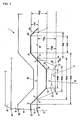
- Fig. 1 is an enlarged cross-sectional view of the relevant part of an optical information recording medium according to an embodiment of the present invention.
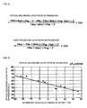
- Fig. 2 is a graph showing a measurement result of the shape of the side of a light-reflective layer according to an embodiment of the present invention.
- Fig. 3 is a graph showing the cross-sectional shape of the light-reflective layer obtained by approximating the curve in Fig. 2 with straight lines, according to an embodiment of the present invention.
- Fig. 4 shows formulae for calculating an optical recording layer ratio in the pregroove and a light-reflective layer ratio in the pregroove, according to an embodiment of the present invention.
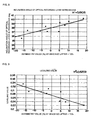
- Fig. 5 is a graph showing the relationship between an asymmetry value at which DC-Jitter > 13% and the optical recording layer ratio in the pregroove, according to an embodiment of the present invention.
- Fig. 6 is a graph showing the relationship between the asymmetry value at which DC-Jitter > 13% and the projecting depth of the light-reflective layer in the pregroove, according to an embodiment of the present invention.
- Fig. 7 is a graph showing the relationship between the asymmetry value at which DC-Jitter > 13% and the thickness of the optical recording layer in the pregroove, according to an embodiment of the present invention.
- Fig. 8 is a graph showing the relationship between the asymmetry value at which DC-Jitter > 13% and the inclination angle of the optical recording layer in the pregroove, according to an embodiment of the present invention.
- Fig. 9 is a graph showing the relationship between the asymmetry value at which DC-Jitter > 13% and the leveling value of the optical recording layer, according to an embodiment of the present invention.
- Fig. 10 shows a chemical formula of a first compound (azo dye) used in Example 1, Example 2, Comparative Example 1, and Comparative Example 2 according to an embodiment of the present invention.
- Fig. 11 shows a chemical formula of a second compound (azo dye) used in Example 3 according to an embodiment of the present invention.
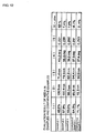
- Fig. 12 is a table showing optical recording layer ratios in a pregroove, projecting depths of a light-reflective layer in the pregroove, thicknesses of the optical recording layer in the pregroove, inclination angles of the optical recording layer in the pregroove, leveling values of the optical recording layer, and DC-Jitter values in Examples 1 to 3 and Comparative Examples 1 and 2 according to an embodiment of the present invention.
- the optical recording layer ratio in the pregroove is 30% to 63%, a media compatible with higher speed recording and high density recording can be realized.
- Fig. 1 is an enlarged cross-sectional view of the relevant part of a disc-shaped optical information recording medium 1. That is, Fig. 1 is a cross-sectional view along with the diameter showing a cut surface of the optical information recording medium 1.
- Fig. 1 schematically shows a cross-sectional view perpendicular to the surface with a pregroove 7 and orthogonal to the direction of the pregroove 7.
- the optical information recording medium 1 includes a transparent substrate 2, an optical recording layer 3 (light-absorbing layer) formed on the substrate 2, a light-reflective layer 4 formed on the optical recording layer 3, and a protective layer 5 formed on the light-reflective layer 4.
- a dummy substrate 6 having a predetermined thickness is further disposed on the protective layer 5 through the adhesive layer to provide a thickness required by the DVD standard.
- the adhesive layer may be doubled as the protective layer.
- the pregroove 7 forming a spiral shape is disposed on the substrate 2.
- a land 8, which is a part other than the pregroove 7, is disposed on both sides of the pregroove 7.
- the optical information recording medium 1 when the optical information recording medium 1 is irradiated with a laser beam 9 (recording beam), the optical recording layer 3 absorbs the energy of the laser beam 9 to generate heat. As a result, a thermal alteration occurs on the side adjacent to the substrate 2 to form a recording pit 10.
- the substrate 2 and the optical recording layer 3 are in contact with each other at a first boundary 11.
- the optical recording layer 3 and the light-reflective layer 4 are in contact with each other at a second boundary 12.
- the light-reflective layer 4 and the protective layer 5 are in contact with each other at a third boundary 13.
- the protective layer 5 and the dummy substrate 6 are in contact with each other at a fourth boundary 14.
- the transparent substrate 2 is composed of a material having a high transparency and a refractive index of, for example, about 1.5 to about 1.7 with a laser beam.
- the substrate 2 is chiefly composed of a resin plate having high impact resistance such as polycarbonate, acrylic resin, and epoxy resin, or a glass plate.
- the optical recording layer 3 formed on the substrate 2 is composed of a light-absorbing substance containing, for example, a dye. Irradiation of the laser beam 9 causes heat generation, melting, sublimation, deformation, or alteration of the optical recording layer 3.
- the optical recording layer 3 is evenly formed by spin coating a solution containing a solvent and a dye such as an azo dye or a cyanine dye on the surface of the substrate 2.
- a dye such as an azo dye or a cyanine dye
- any material for optical recording can be used for the optical recording layer 3
- light-absorbing organic dyes are preferably used.
- the light-reflective layer 4 is a metal film having a high thermal conductivity and a high light reflectivity.
- the light-reflective layer 4 is formed by vacuuming deposition or sputtering using gold, silver, copper, aluminum, or an alloy thereof.
- the protective layer 5 is composed of a resin having a high impact resistance, as in the substrate 2, and superior adhesiveness.
- the protective layer 5 is formed by applying an ultraviolet-curing resin by spin coating. The resultant substrate is then irradiated with ultraviolet rays to cure the resin.
- the dummy substrate 6 is composed of the same material as the substrate 2 to provide the predetermined thickness of about 1.2 mm.
- Fig. 1 dimensions of each part of the optical information recording medium 1 are defined as shown in the figure.
- the upper left corner is defined as point A
- the lower left corner is defined as point B
- the lower right corner is defined as point C
- the upper right corner is defined as point D.
- the upper left corner of the light-reflective layer 4 disposed on the land 8 is defined as point E.
- the intersection of an opening level line 15 (virtual line) and the left slanted part of the light-reflective layer 4 is defined as point F.
- the opening level line 15 extends from the land 8 to the opening of the pregroove 7 at the same level as the first boundary 11.
- the lower right corner of the light-reflective layer 4 is defined as point H.
- the intersection of the opening level line 15 and the right slanted part of the light-reflective layer 4 is defined as point I.
- the upper right corner of the light-reflective layer 4 disposed on the land 8 is defined as point J.
- the maximum width (width along the diameter of the optical information recording medium 1) of a recess of the light-reflective layer 4 above the pregroove 7 is defined as Wdt (the length of line EJ).
- the minimum width of the recess of the light-reflective layer 4 in the pregroove 7 is defined as Wdb (the length of line GH).
- the maximum width of the optical recording layer 3 in the pregroove 7 is defined as Wst (the length of line AD).
- the minimum width of the optical recording layer 3 in the pregroove 7 is defined as Wsb (the length of line BC).
- the width of the protrusion of the light-reflective layer 4 above the land 8 is defined as Wdl (the length of line JE1).
- the width on the land 8 of the optical recording layer 3 is defined as Wsl (the length of line DA1).
- the width of the optical recording layer 3 between the optical recording layer 3 and the light-reflective layer 4 at the same level as the first boundary 11 of the land 8 is defined as Wx (the length of lines AF and ID).
- the depth (dye groove depth) from the second boundary 12 of the light-reflective layer 4 above the land 8 to the second boundary 12 in the pregroove 7 is defined as Hdg (the length between line JE and line GH).
- the depth of the optical recording layer 3 on the land 8 is defined as Hdl (the length between line JE and line DA).
- the depth of the pregroove 7 (substrate groove depth) is defined as Hsg (the length between line DA and line BC).
- the depth between the optical recording layer 3 and the light-reflective layer 4 in the pregroove 7 is defined as Hsd (the length between line GH and line BC).
- the angle of the slanted part of the light-reflective layer 4 in the optical recording layer 3 (dye groove angle) is defined as angle ⁇ .
- the angle of the slanted part of the optical recording layer 3 in the substrate 2 (substrate groove angle) is defined as angle ⁇ .
- the cross-sectional shape and each dimension of the optical information recording medium 1 were measured as follows: A part of the second boundary 12 between the optical recording layer 3 and the light-reflective layer 4 was broken apart by inserting a metal spatula from a center hole of the optical information recording medium 1 to decompose the optical information recording medium 1. Subsequently, the organic dye material (optical recording layer 3) adhered to a side of the light-reflective layer 4 was washed off with ethanol. This sample was used for measuring the shape of the dye layer, except parts damaged during decomposing with the spatula. The organic dye material (optical recording layer 3) adhered to a side of the substrate 2 was washed off with ethanol. This sample was used for measuring the shape of the substrate 2, except parts damaged during decomposing with the spatula. The shapes of each part were measured with an atomic force microscope (AFM) (from ThermoMicroscopes, Autoprobe M5).
- AFM atomic force microscope
- Fig. 2 is a graph showing a result of measuring the cross-sectional shape of the light-reflective layer 4. Although the actual measured shape is shown by a curved line, the curved line is approximated with straight lines so that a calculation is easily performed using data such as the depth, the full width at half-maximum, and the angle.
- Fig. 3 is a graph showing the cross-sectional shape of the light-reflective layer 4 obtained by approximating the curved line in Fig. 2 with straight lines. The dotted line shows the actual measured shape and the continuous line shows the approximate shape. The shape of the substrate 2 was also measured in the same way as described above.
- the laser power of the laser beam 9 rapidly heats the organic dye material in the pregroove 7.
- the heat is diffused through the optical recording layer 3 and the light-reflective layer 4. This diffusing heat is transferred to the adjacent tracks or to the pregroove 7. These areas are heated to some degree, forming a preheated state.
- an enlarged recording pit is formed due to the effect of the preheating.
- the shape of the formed recording pit 10 becomes different from a recording mark that supposed to be recorded.
- the recording power is about 6 to 10 mW at 1 ⁇ speed recording (about 3.5 m/s), about 15 to 20 mW at 4 ⁇ speed recording, about 25 to 30 mW at 8 ⁇ speed recording, and 40 mW or more at 16 ⁇ speed recording.
- the recording power is about 6 to 10 mW at 1 ⁇ speed recording (about 3.5 m/s), about 15 to 20 mW at 4 ⁇ speed recording, about 25 to 30 mW at 8 ⁇ speed recording, and 40 mW or more at 16 ⁇ speed recording.
- the factors to control the heat generated during recording in the optical information recording medium 1 are roughly divided into control of heat generation and control of heat dissipation.
- the control of heat generation relates to physical properties of materials such as the calorific value and the decomposition temperature of the material itself of the optical recording layer 3.
- the control of heat dissipation closely relates to configuration factors such as the shapes of the optical recording layer 3 and the substrate 2, that is, the thickness of the optical recording layer 3, and the shape of the second boundary 12 between the optical recording layer 3 and the light-reflective layer 4.
- the optical recording layer 3, which is a thin film composed of an organic dye material is disposed between the light-reflective layer 4 which is a metal thin film, and the substrate 2 composed of polycarbonate.
- the metal (light-reflective layer 4) has a thermal conductivity higher than that of the polycarbonate, a plastic material (substrate 2). Therefore, the control of heat dissipation closely relates to the configuration factors.
- the present inventors have found that it is difficult to achieve a significant advantage by controlling the heat generation, whereas a significant advantage can be achieved by controlling the heat dissipation based on the configuration factors such as the shapes of the optical recording layer 3 and the substrate 2.
- the control of heat dissipation more specifically, the shapes of the optical recording layer 3 and the light-reflective layer 4 in the pregroove 7, are the most dominant in thermal control during high speed recording.
- the present invention has been accomplished by paying attention to this point.
- the shape of the optical recording layer 3 represented by the following items significantly affects thermal control (control of heat dissipation) during high speed recording.
- the following Items (1) and (2) particularly affect thermal control.
- the above Items are preferably in the following range.
- the above Items are preferably in the following range.
- the above Items (1) to (5) in the present invention independently affect thermal control during high speed recording.
- the shape of the optical information recording medium must satisfy at least one of the conditions defined by Items (1) to (5).
- Item (1) and Item (2) particularly affect thermal control. Therefore, the shape must satisfy at least one of the conditions defined by the Items (1) and (2).
- Fig. 5 is a graph showing the relationship between an asymmetry value at which DC-Jitter > 13% and the optical recording layer ratio in the pregroove 7.
- the abscissa represents an asymmetry value at which the DC-Jitter exceeds 13%, and the ordinate represents the optical recording layer ratio in the pregroove.
- the DC-Jitter represents the data to clock jitter.
- the DC-Jitter is a jitter value obtained when the optical information recording medium 1 is rotated by 360 degrees, and represents the fluctuation of the recording pit 10.
- the asymmetry value represents the deviation of the recording pits 10 in DVD-R from the intended recording position. The deviation is calculated for the average values in the pit length of 3T to 14T.
- An experimental result shows that, in order to further improve the recording sensitivity of a recording media, the asymmetry value should be shifted to the positive side as much as possible in the design. Therefore, in high speed recording, the asymmetry value is preferably in the range of -5% to 15%.
- the asymmetry value is preferably shifted from -5% to the positive side, and at 16 ⁇ speed, the asymmetry value is preferably shifted from +5% to the positive side.
- a recording result at 16 ⁇ speed is expected based on the result of DC-Jitters obtained from recordings at 1 ⁇ speed, 2 ⁇ speed, 4 ⁇ speed, 6 ⁇ speed, and 8 ⁇ speed.
- the optical recording layer ratio in the pregroove decreases (that is, as the light-reflective layer ratio in the pregroove increases)
- the asymmetry value at which the DC-Jitter exceeds 13% is shifted to the positive side.
- the optical recording layer ratio in the pregroove is preferably not over 63%.
- the optical recording layer ratio in the pregroove is preferably not over 57%.
- Fig. 6 is a graph showing the relationship between the asymmetry value at which DC-Jitter > 13% and the projecting depth of the light-reflective layer 4 in the pregroove 7. As the projecting depth of the light-reflective layer 4 in the pregroove 7 increases, the asymmetry value at which the DC-Jitter exceeds 13% is shifted to the positive side. As supported by the graph in Fig. 6, the projecting depth of the light-reflective layer 4 in the pregroove 7 is preferably at least 83 nm, and more preferably, at least 93 nm.
- Fig. 7 is a graph showing the relationship between the asymmetry value at which DC-Jitter > 13% and the thickness of the optical recording layer 3 in the pregroove 7. As the thickness of the optical recording layer 3 in the pregroove 7 decreases, the asymmetry value at which the DC-Jitter exceeds 13% is shifted to the positive side. As supported by the graph in Fig. 7, the thickness of the optical recording layer 3 in the pregroove 7 is preferably not over 90 nm, and more preferably, not over 83 nm.
- Fig. 8 is a graph showing the relationship between the asymmetry value at which DC-Jitter > 13% and the inclination angle of the optical recording layer 3 in the pregroove 7. As the inclination angle increases, the asymmetry value at which the DC-Jitter exceeds 13% is shifted to the positive side. As supported by the graph in Fig. 8, the inclination angle of the optical recording layer 3 in the pregroove 7 is preferably at least 37.5 degrees, and more preferably, at least 38.5 degrees.
- Fig. 9 is a graph showing the relationship between the asymmetry value at which DC-Jitter > 13% and the leveling value of the optical recording layer 3. As the leveling value decreases, the asymmetry value at which the DC-Jitter exceeds 13% is shifted to the positive side. As supported by the graph in Fig. 9, the leveling value of the optical recording layer 3 is preferably not over 0.29, and more preferably, not over 0.26.
- a first compound (azo dye) (0.2 g) shown in Fig. 10 was dissolved in 2,2,3,3-tetrafluoro-1-propanol (10 mL) to prepare an coating solution.
- a disc-shaped substrate 2 composed of polycarbonate and having an outer diameter of 120 mm and a thickness of 0.6 mm was prepared.
- the substrate 2 included a continuous pregroove 7 having a depth of 180 nm.
- the above solution was applied on the substrate 2 by spin coating to form an optical recording layer 3 having an average dye film thickness of about 50 nm.
- a light-reflective layer 4 having a thickness of 100 nm was formed on the optical recording layer 3 by sputtering silver (Ag).
- an ultraviolet-curing resin SD-318 (from Dainippon Ink and Chemicals, Incorporated) was applied on the light-reflective layer 4 by spin coating.
- the resultant substrate 2 was irradiated with ultraviolet rays to cure the resin, forming a protective layer 5.
- An adhesive layer composed of an ultraviolet-curing resin was applied on the surface of the protective layer 5 to bond with a dummy substrate 6 composed of the same material and having the same shape as the substrate 2.
- the resultant substrate was irradiated with ultraviolet rays to cure the adhesive layer.
- a write-once optical information recording medium 1 was prepared.
- the factors of the substrate 2 such as shape, adjustments of the coating solution including viscosity or the concentration, and the conditions for applying the coating solution by spin coating such as the revolution speed.
- a disc checker DDU-1000, from Pulstec Industrial Co., Ltd.
- an EFM signal was recorded with a linear velocity of 28 m/s at 8 ⁇ speed.
- the signal was played back with a laser output of 0.7 mW using the disc checker.
- the reflectance, the modulation amplitude, the error rate, and the jitter were measured.
- the reflectance (R top ) was 45.3%
- the modulation amplitude (I 14 /I top ) was 75.3%
- the error rate was 1.4
- the jitter was 6.5%.
- the reflectance must exceed 45%
- the modulation amplitude must exceed 60%
- the error rate (PI value) must be less than 280
- the jitter must be less than 8%.
- Another disc other than the disc used for evaluating the recording property, was prepared. This disc was broken apart at the boundary (second boundary 12) between the light-reflective layer 4 and the optical recording layer 3, and decomposed. The methods of decomposing etc. were the same as described above. The shape of the decomposed disc was measured with an AFM measuring apparatus.
- the substrate groove angle ( ⁇ ) was 69.1 degrees, and a substrate groove width (full width at half-maximum) was 301 nm.
- the substrate groove width (full width at half-maximum) represents a width at the half-way position of the substrate groove depth (Hsg).
- a write-once optical information recording medium 1 was prepared as in Example 1, except that the average dye film thickness was about 56 nm, which was thicker than that of Example 1 by about 12%.
- the recording medium was evaluated and analyzed as in Example 1.
- the reflectance, the modulation amplitude, the error rate, and the jitter were measured as in Example 1.
- the reflectance (R top ) was 46.4%
- the modulation amplitude (I 14 /I top ) was 80.6%
- the error rate was 2.1
- the jitter was 7.4%.
- the substrate groove angle ( ⁇ ) was 69.1 degrees
- the substrate groove width full width at half-maximum
- a write-once optical information recording medium 1 was prepared as in Example 1, except that the dye was changed from the first compound (shown in Fig. 10) to a second compound (shown in Fig. 11, an azo dye).
- the recording medium was evaluated and analyzed as in Example 1.
- the reflectance, the modulation amplitude, the error rate, and the jitter were measured as in Example 1.
- the reflectance (R top ) was 53%
- the modulation amplitude (I 14 /I top ) was 76.1%
- the error rate was 2.0
- the jitter was 7.9%.
- the substrate groove angle ( ⁇ ) was 69.1 degrees
- the substrate groove width (full width at half-maximum) was 301 nm.
- Numerical values related to, for example, the optical recording layer ratio in the pregroove shown in Fig. 4 were as follows:
- a write-once optical information recording medium 1 was prepared as in Example 1, except that the average dye film thickness was about 64 nm, which was thicker than that of Example 1 by about 28%.
- the recording medium was evaluated and analyzed as in Example 1.
- the reflectance, the modulation amplitude, the error rate, and the jitter were measured as in Example 1.
- the reflectance (R top ) was 45%
- the modulation amplitude (I 14/ I top ) was 80.9%
- the error rate was 314.0
- the jitter was 14.1%.
- the substrate groove angle ( ⁇ ) was 69.1 degrees
- the substrate groove width full width at half-maximum
- a write-once optical information recording medium 1 was prepared as in Example 1, except that an optical recording layer 3 having an average dye film thickness of about 65 nm on a substrate 2 including a pregroove 7 having a depth of about 165 nm.
- the recording medium was evaluated and analyzed as in Example 1.
- the reflectance, the modulation amplitude, the error rate, and the jitter were measured as in Example 1.
- the reflectance (R top ) was 53.1%
- the modulation amplitude (I 14 /I top ) was 77.1%
- the error rate was 418.8, and the jitter was 21.4%.
- the substrate groove angle ( ⁇ ) was 69.1 degrees
- the substrate groove width (full width at half-maximum) was 302 nm.
- Numerical values related to, for example, the optical recording layer ratio in the pregroove shown in Fig. 4 were as follows:
Landscapes
- Optical Record Carriers And Manufacture Thereof (AREA)
- Optical Recording Or Reproduction (AREA)
- Thermal Transfer Or Thermal Recording In General (AREA)
Applications Claiming Priority (2)
| Application Number | Priority Date | Filing Date | Title |
|---|---|---|---|
| JP2003433005 | 2003-12-26 | ||
| JP2003433005A JP2005190616A (ja) | 2003-12-26 | 2003-12-26 | 光情報記録媒体 |
Publications (2)
| Publication Number | Publication Date |
|---|---|
| EP1548716A2 true EP1548716A2 (de) | 2005-06-29 |
| EP1548716A3 EP1548716A3 (de) | 2007-06-20 |
Family
ID=34545070
Family Applications (1)
| Application Number | Title | Priority Date | Filing Date |
|---|---|---|---|
| EP04258041A Withdrawn EP1548716A3 (de) | 2003-12-26 | 2004-12-22 | Optisches Informationsaufzeichnungsmedium |
Country Status (6)
| Country | Link |
|---|---|
| US (1) | US7542406B2 (de) |
| EP (1) | EP1548716A3 (de) |
| JP (1) | JP2005190616A (de) |
| KR (1) | KR100785708B1 (de) |
| CN (1) | CN100456372C (de) |
| TW (1) | TWI277086B (de) |
Families Citing this family (5)
| Publication number | Priority date | Publication date | Assignee | Title |
|---|---|---|---|---|
| TWI237259B (en) * | 2004-12-07 | 2005-08-01 | Ind Tech Res Inst | Write-once optical recording mediums |
| JP4660217B2 (ja) * | 2005-01-31 | 2011-03-30 | 株式会社東芝 | 記憶媒体、再生方法、記録方法、再生装置及び記録装置 |
| CN101379560B (zh) * | 2006-02-02 | 2011-04-06 | 太阳诱电株式会社 | 光信息记录介质、以及其制造方法及记录方法 |
| JP2008010129A (ja) * | 2006-06-30 | 2008-01-17 | Toshiba Corp | 情報記録媒体、及びディスク装置 |
| JP2008010107A (ja) * | 2006-06-30 | 2008-01-17 | Toshiba Corp | 情報記録媒体、及びディスク装置 |
Family Cites Families (26)
| Publication number | Priority date | Publication date | Assignee | Title |
|---|---|---|---|---|
| GB8314918D0 (en) | 1983-05-31 | 1983-07-06 | Vickers Plc | Radiation sensitive compositions |
| US5274623A (en) * | 1990-07-19 | 1993-12-28 | Fuji Photo Film Co., Ltd. | Information recording medium having high modulation degree |
| CA2065653A1 (en) * | 1991-04-16 | 1992-10-17 | Tadashi Koike | Optical recording medium |
| JP2839062B2 (ja) | 1993-03-30 | 1998-12-16 | 太陽誘電株式会社 | 書き込み可能な光情報記録媒体 |
| JP3652017B2 (ja) * | 1995-08-23 | 2005-05-25 | 三井化学株式会社 | 光記録媒体 |
| EP0911820A4 (de) * | 1997-04-24 | 2002-01-16 | Matsushita Electric Industrial Co Ltd | Optisches aufzeichnungsmedium und substrat dafür |
| TW374917B (en) | 1997-05-28 | 1999-11-21 | Mitsui Chemicals Inc | Optical recording medium |
| JP3685922B2 (ja) * | 1997-11-05 | 2005-08-24 | Tdk株式会社 | 光記録媒体およびその記録方法 |
| JP3883277B2 (ja) | 1998-01-27 | 2007-02-21 | 三井化学株式会社 | 光記録媒体およびその製造方法 |
| JP4078773B2 (ja) | 1999-02-26 | 2008-04-23 | 三菱化学株式会社 | 金属キレート色素及び該色素を使用した光学記録媒体 |
| JP2000268402A (ja) * | 1999-03-15 | 2000-09-29 | Fuji Photo Film Co Ltd | 光情報記録媒体 |
| JP2000268409A (ja) | 1999-03-18 | 2000-09-29 | Hitachi Maxell Ltd | 光記録媒体 |
| EP1256947A1 (de) * | 2000-02-14 | 2002-11-13 | Taiyo Yuden Co., Ltd. | Medium zur aufzeichnung optischer informationen |
| TWI237820B (en) | 2000-04-17 | 2005-08-11 | Mitsubishi Chem Corp | Optical recording medium |
| JP2001344812A (ja) * | 2000-06-02 | 2001-12-14 | Fuji Photo Film Co Ltd | 光情報記録媒体 |
| JP2002150563A (ja) * | 2000-09-01 | 2002-05-24 | Mitsubishi Chemicals Corp | 光記録方法および光記録媒体 |
| WO2002037486A1 (en) * | 2000-10-23 | 2002-05-10 | Mitsui Chemicals, Inc. | Optical recording medium |
| JP2002254822A (ja) * | 2000-12-13 | 2002-09-11 | Mitsui Chemicals Inc | 光記録媒体およびその製造方法 |
| US20020106475A1 (en) * | 2000-12-13 | 2002-08-08 | Norihiko Mihara | Optical recording medium and process for production thereof |
| JP2002222542A (ja) | 2001-01-26 | 2002-08-09 | Taiyo Yuden Co Ltd | 光情報記録媒体 |
| JP2003140300A (ja) | 2001-11-02 | 2003-05-14 | Mitsui Chemicals Inc | 光記録媒体 |
| JP2003288736A (ja) * | 2002-03-27 | 2003-10-10 | Mitsui Chemicals Inc | 光情報記録媒体 |
| JP2003312146A (ja) * | 2002-04-25 | 2003-11-06 | Mitsubishi Chemicals Corp | 光学記録媒体 |
| JP2004272983A (ja) | 2003-03-06 | 2004-09-30 | Ricoh Co Ltd | 光記録再生方法 |
| JP2006134518A (ja) * | 2004-11-08 | 2006-05-25 | Taiyo Yuden Co Ltd | 光情報記録媒体 |
| US7507524B2 (en) | 2005-09-06 | 2009-03-24 | Mitsubishi Kagaku Media Co., Ltd. | Azo-metal chelate dye and optical recording medium |
-
2003
- 2003-12-26 JP JP2003433005A patent/JP2005190616A/ja active Pending
-
2004
- 2004-11-26 TW TW093136559A patent/TWI277086B/zh not_active IP Right Cessation
- 2004-12-07 KR KR1020040102323A patent/KR100785708B1/ko not_active Expired - Fee Related
- 2004-12-22 EP EP04258041A patent/EP1548716A3/de not_active Withdrawn
- 2004-12-23 US US11/020,912 patent/US7542406B2/en not_active Expired - Fee Related
- 2004-12-27 CN CNB2004101034285A patent/CN100456372C/zh not_active Expired - Fee Related
Also Published As
| Publication number | Publication date |
|---|---|
| TW200522056A (en) | 2005-07-01 |
| JP2005190616A (ja) | 2005-07-14 |
| KR100785708B1 (ko) | 2007-12-18 |
| EP1548716A3 (de) | 2007-06-20 |
| US20050169160A1 (en) | 2005-08-04 |
| US7542406B2 (en) | 2009-06-02 |
| KR20050066998A (ko) | 2005-06-30 |
| TWI277086B (en) | 2007-03-21 |
| CN1637896A (zh) | 2005-07-13 |
| HK1075123A1 (zh) | 2005-12-02 |
| CN100456372C (zh) | 2009-01-28 |
Similar Documents
| Publication | Publication Date | Title |
|---|---|---|
| US5075147A (en) | Method for optically recording information and information recorded medium | |
| US20050180308A1 (en) | Optical recording medium and method of recording an image | |
| CN100593202C (zh) | 光记录媒质 | |
| US7542406B2 (en) | Optical information recording medium | |
| JP4284025B2 (ja) | 光情報記録媒体 | |
| EP1667122B1 (de) | Aufzeichnungs-/wiedergabeverfahren und -einrichtung für ein dvd-medium des einmal beschreibbaren typs auf pigmentbasis | |
| EP1667120B1 (de) | Optisches Informationsaufzeichnungsmedium mit Azo-Metallkomplex Farbstoff | |
| US7727706B2 (en) | Recording method for dye-based recordable optical recording medium | |
| JP3543464B2 (ja) | 光記録媒体及び情報記録方法 | |
| TW501127B (en) | Optical recording medium | |
| JP2523421B2 (ja) | 光記録媒体 | |
| JP3495589B2 (ja) | 光記録媒体 | |
| JP4284036B2 (ja) | 光情報記録媒体 | |
| EP1826751B1 (de) | Aufzeichnungsverfahren für ein beschreibbares DVD-Medium auf Farbstoffbasis und Aufzeichnungsgerät | |
| JP3099276B2 (ja) | 光情報記録媒体およびその記録方法 | |
| JP4160998B2 (ja) | 光情報記録再生方法 | |
| HK1075123B (en) | Optical information recording medium | |
| JP2002237100A (ja) | 光記録媒体 | |
| HK1112103A (en) | Optical information recording medium | |
| HK1090746B (en) | Optical information recording medium | |
| JP2004178637A (ja) | 光記録媒体 | |
| JP2006123558A (ja) | 情報記録方法および光情報記録媒体 | |
| JP2006031883A (ja) | 光ディスク | |
| JPH09147414A (ja) | 光記録方法及び光情報記録媒体 | |
| JPH06103607A (ja) | 光記録媒体 |
Legal Events
| Date | Code | Title | Description |
|---|---|---|---|
| PUAI | Public reference made under article 153(3) epc to a published international application that has entered the european phase |
Free format text: ORIGINAL CODE: 0009012 |
|
| AK | Designated contracting states |
Kind code of ref document: A2 Designated state(s): AT BE BG CH CY CZ DE DK EE ES FI FR GB GR HU IE IS IT LI LT LU MC NL PL PT RO SE SI SK TR |
|
| AX | Request for extension of the european patent |
Extension state: AL BA HR LV MK YU |
|
| PUAL | Search report despatched |
Free format text: ORIGINAL CODE: 0009013 |
|
| AK | Designated contracting states |
Kind code of ref document: A3 Designated state(s): AT BE BG CH CY CZ DE DK EE ES FI FR GB GR HU IE IS IT LI LT LU MC NL PL PT RO SE SI SK TR |
|
| AX | Request for extension of the european patent |
Extension state: AL BA HR LV MK YU |
|
| 17P | Request for examination filed |
Effective date: 20070925 |
|
| 17Q | First examination report despatched |
Effective date: 20071214 |
|
| AKX | Designation fees paid |
Designated state(s): AT BE BG CH CY CZ DE DK EE ES FI FR GB GR HU IE IS IT LI LT LU MC NL PL PT RO SE SI SK TR |
|
| STAA | Information on the status of an ep patent application or granted ep patent |
Free format text: STATUS: THE APPLICATION IS DEEMED TO BE WITHDRAWN |
|
| 18D | Application deemed to be withdrawn |
Effective date: 20110714 |