EP1826751B1 - Aufzeichnungsverfahren für ein beschreibbares DVD-Medium auf Farbstoffbasis und Aufzeichnungsgerät - Google Patents
Aufzeichnungsverfahren für ein beschreibbares DVD-Medium auf Farbstoffbasis und Aufzeichnungsgerät Download PDFInfo
- Publication number
- EP1826751B1 EP1826751B1 EP07102794A EP07102794A EP1826751B1 EP 1826751 B1 EP1826751 B1 EP 1826751B1 EP 07102794 A EP07102794 A EP 07102794A EP 07102794 A EP07102794 A EP 07102794A EP 1826751 B1 EP1826751 B1 EP 1826751B1
- Authority
- EP
- European Patent Office
- Prior art keywords
- recording
- mark
- pulse
- shortest
- dye
- Prior art date
- Legal status (The legal status is an assumption and is not a legal conclusion. Google has not performed a legal analysis and makes no representation as to the accuracy of the status listed.)
- Ceased
Links
- 238000000034 method Methods 0.000 title claims description 49
- 239000010410 layer Substances 0.000 claims description 77
- 230000003287 optical effect Effects 0.000 claims description 74
- 239000000758 substrate Substances 0.000 claims description 46
- 238000001816 cooling Methods 0.000 claims description 24
- 238000010438 heat treatment Methods 0.000 claims description 16
- 229920005989 resin Polymers 0.000 claims description 12
- 239000011347 resin Substances 0.000 claims description 12
- 239000011241 protective layer Substances 0.000 claims description 11
- 230000001681 protective effect Effects 0.000 claims description 9
- 239000012790 adhesive layer Substances 0.000 claims description 8
- 229910052782 aluminium Inorganic materials 0.000 claims description 7
- 230000001678 irradiating effect Effects 0.000 claims description 7
- 238000011217 control strategy Methods 0.000 claims description 6
- 229910052737 gold Inorganic materials 0.000 claims description 6
- 229910052709 silver Inorganic materials 0.000 claims description 6
- 239000000853 adhesive Substances 0.000 claims description 3
- 230000001070 adhesive effect Effects 0.000 claims description 3
- 238000001514 detection method Methods 0.000 claims description 3
- 239000000956 alloy Substances 0.000 claims description 2
- 229910045601 alloy Inorganic materials 0.000 claims description 2
- 230000008033 biological extinction Effects 0.000 claims description 2
- 238000000354 decomposition reaction Methods 0.000 claims description 2
- 230000001360 synchronised effect Effects 0.000 claims description 2
- 230000009977 dual effect Effects 0.000 claims 1
- 239000000975 dye Substances 0.000 description 87
- 239000000463 material Substances 0.000 description 19
- 229910052751 metal Inorganic materials 0.000 description 18
- 239000002184 metal Substances 0.000 description 18
- 230000000052 comparative effect Effects 0.000 description 17
- 150000002739 metals Chemical class 0.000 description 11
- 238000005516 engineering process Methods 0.000 description 8
- 238000000576 coating method Methods 0.000 description 7
- 230000010365 information processing Effects 0.000 description 6
- 238000005259 measurement Methods 0.000 description 6
- 239000004065 semiconductor Substances 0.000 description 5
- 238000013500 data storage Methods 0.000 description 4
- 239000007788 liquid Substances 0.000 description 4
- 150000002736 metal compounds Chemical class 0.000 description 4
- 238000002310 reflectometry Methods 0.000 description 4
- ZWEHNKRNPOVVGH-UHFFFAOYSA-N 2-Butanone Chemical compound CCC(C)=O ZWEHNKRNPOVVGH-UHFFFAOYSA-N 0.000 description 3
- CSCPPACGZOOCGX-UHFFFAOYSA-N Acetone Chemical compound CC(C)=O CSCPPACGZOOCGX-UHFFFAOYSA-N 0.000 description 3
- UHOVQNZJYSORNB-UHFFFAOYSA-N Benzene Chemical compound C1=CC=CC=C1 UHOVQNZJYSORNB-UHFFFAOYSA-N 0.000 description 3
- YMWUJEATGCHHMB-UHFFFAOYSA-N Dichloromethane Chemical compound ClCCl YMWUJEATGCHHMB-UHFFFAOYSA-N 0.000 description 3
- RTZKZFJDLAIYFH-UHFFFAOYSA-N Diethyl ether Chemical compound CCOCC RTZKZFJDLAIYFH-UHFFFAOYSA-N 0.000 description 3
- LFQSCWFLJHTTHZ-UHFFFAOYSA-N Ethanol Chemical compound CCO LFQSCWFLJHTTHZ-UHFFFAOYSA-N 0.000 description 3
- XEKOWRVHYACXOJ-UHFFFAOYSA-N Ethyl acetate Chemical compound CCOC(C)=O XEKOWRVHYACXOJ-UHFFFAOYSA-N 0.000 description 3
- OKKJLVBELUTLKV-UHFFFAOYSA-N Methanol Chemical compound OC OKKJLVBELUTLKV-UHFFFAOYSA-N 0.000 description 3
- ZMXDDKWLCZADIW-UHFFFAOYSA-N N,N-Dimethylformamide Chemical compound CN(C)C=O ZMXDDKWLCZADIW-UHFFFAOYSA-N 0.000 description 3
- 239000013522 chelant Substances 0.000 description 3
- 238000012937 correction Methods 0.000 description 3
- OVTCUIZCVUGJHS-UHFFFAOYSA-N dipyrrin Chemical compound C=1C=CNC=1C=C1C=CC=N1 OVTCUIZCVUGJHS-UHFFFAOYSA-N 0.000 description 3
- 239000003822 epoxy resin Substances 0.000 description 3
- LNEPOXFFQSENCJ-UHFFFAOYSA-N haloperidol Chemical compound C1CC(O)(C=2C=CC(Cl)=CC=2)CCN1CCCC(=O)C1=CC=C(F)C=C1 LNEPOXFFQSENCJ-UHFFFAOYSA-N 0.000 description 3
- VMGAPWLDMVPYIA-HIDZBRGKSA-N n'-amino-n-iminomethanimidamide Chemical compound N\N=C\N=N VMGAPWLDMVPYIA-HIDZBRGKSA-N 0.000 description 3
- VLKZOEOYAKHREP-UHFFFAOYSA-N n-Hexane Chemical compound CCCCCC VLKZOEOYAKHREP-UHFFFAOYSA-N 0.000 description 3
- 229920006122 polyamide resin Polymers 0.000 description 3
- 229920000515 polycarbonate Polymers 0.000 description 3
- 239000004417 polycarbonate Substances 0.000 description 3
- 229920005668 polycarbonate resin Polymers 0.000 description 3
- 239000004431 polycarbonate resin Substances 0.000 description 3
- 229920000647 polyepoxide Polymers 0.000 description 3
- BOLDJAUMGUJJKM-LSDHHAIUSA-N renifolin D Natural products CC(=C)[C@@H]1Cc2c(O)c(O)ccc2[C@H]1CC(=O)c3ccc(O)cc3O BOLDJAUMGUJJKM-LSDHHAIUSA-N 0.000 description 3
- 239000002904 solvent Substances 0.000 description 3
- 238000004544 sputter deposition Methods 0.000 description 3
- 238000003860 storage Methods 0.000 description 3
- YKENVNAJIQUGKU-UHFFFAOYSA-N tetraazaporphin Chemical compound C=1C(C=N2)=NC2=NC(NN2)=NC2=CC(C=C2)=NC2=CC2=NC=1C=C2 YKENVNAJIQUGKU-UHFFFAOYSA-N 0.000 description 3
- 229910052718 tin Inorganic materials 0.000 description 3
- XNWFRZJHXBZDAG-UHFFFAOYSA-N 2-METHOXYETHANOL Chemical compound COCCO XNWFRZJHXBZDAG-UHFFFAOYSA-N 0.000 description 2
- ZNQVEEAIQZEUHB-UHFFFAOYSA-N 2-ethoxyethanol Chemical compound CCOCCO ZNQVEEAIQZEUHB-UHFFFAOYSA-N 0.000 description 2
- 229920000178 Acrylic resin Polymers 0.000 description 2
- 239000004925 Acrylic resin Substances 0.000 description 2
- HEDRZPFGACZZDS-UHFFFAOYSA-N Chloroform Chemical compound ClC(Cl)Cl HEDRZPFGACZZDS-UHFFFAOYSA-N 0.000 description 2
- IAZDPXIOMUYVGZ-UHFFFAOYSA-N Dimethylsulphoxide Chemical compound CS(C)=O IAZDPXIOMUYVGZ-UHFFFAOYSA-N 0.000 description 2
- KFZMGEQAYNKOFK-UHFFFAOYSA-N Isopropanol Chemical compound CC(C)O KFZMGEQAYNKOFK-UHFFFAOYSA-N 0.000 description 2
- OFBQJSOFQDEBGM-UHFFFAOYSA-N Pentane Chemical compound CCCCC OFBQJSOFQDEBGM-UHFFFAOYSA-N 0.000 description 2
- 239000006087 Silane Coupling Agent Substances 0.000 description 2
- VYPSYNLAJGMNEJ-UHFFFAOYSA-N Silicium dioxide Chemical compound O=[Si]=O VYPSYNLAJGMNEJ-UHFFFAOYSA-N 0.000 description 2
- WYURNTSHIVDZCO-UHFFFAOYSA-N Tetrahydrofuran Chemical compound C1CCOC1 WYURNTSHIVDZCO-UHFFFAOYSA-N 0.000 description 2
- XLOMVQKBTHCTTD-UHFFFAOYSA-N Zinc monoxide Chemical compound [Zn]=O XLOMVQKBTHCTTD-UHFFFAOYSA-N 0.000 description 2
- NIXOWILDQLNWCW-UHFFFAOYSA-N acrylic acid group Chemical group C(C=C)(=O)O NIXOWILDQLNWCW-UHFFFAOYSA-N 0.000 description 2
- 239000002216 antistatic agent Substances 0.000 description 2
- CUFNKYGDVFVPHO-UHFFFAOYSA-N azulene Chemical compound C1=CC=CC2=CC=CC2=C1 CUFNKYGDVFVPHO-UHFFFAOYSA-N 0.000 description 2
- 239000000919 ceramic Substances 0.000 description 2
- 229910052804 chromium Inorganic materials 0.000 description 2
- 239000011248 coating agent Substances 0.000 description 2
- 238000004891 communication Methods 0.000 description 2
- 150000001875 compounds Chemical class 0.000 description 2
- JHIVVAPYMSGYDF-UHFFFAOYSA-N cyclohexanone Chemical compound O=C1CCCCC1 JHIVVAPYMSGYDF-UHFFFAOYSA-N 0.000 description 2
- 230000003247 decreasing effect Effects 0.000 description 2
- 238000010586 diagram Methods 0.000 description 2
- 239000002270 dispersing agent Substances 0.000 description 2
- 230000000694 effects Effects 0.000 description 2
- 229920001971 elastomer Polymers 0.000 description 2
- 239000003063 flame retardant Substances 0.000 description 2
- 229910052732 germanium Inorganic materials 0.000 description 2
- 239000011521 glass Substances 0.000 description 2
- 238000001746 injection moulding Methods 0.000 description 2
- 229920000554 ionomer Polymers 0.000 description 2
- 239000000314 lubricant Substances 0.000 description 2
- 125000001434 methanylylidene group Chemical group [H]C#[*] 0.000 description 2
- UAEPNZWRGJTJPN-UHFFFAOYSA-N methylcyclohexane Chemical compound CC1CCCCC1 UAEPNZWRGJTJPN-UHFFFAOYSA-N 0.000 description 2
- 238000000465 moulding Methods 0.000 description 2
- 229920005615 natural polymer Polymers 0.000 description 2
- 229910052759 nickel Inorganic materials 0.000 description 2
- 239000011368 organic material Substances 0.000 description 2
- 239000003960 organic solvent Substances 0.000 description 2
- YNPNZTXNASCQKK-UHFFFAOYSA-N phenanthrene Chemical compound C1=CC=C2C3=CC=CC=C3C=CC2=C1 YNPNZTXNASCQKK-UHFFFAOYSA-N 0.000 description 2
- 239000005011 phenolic resin Substances 0.000 description 2
- 239000004033 plastic Substances 0.000 description 2
- 229920003023 plastic Polymers 0.000 description 2
- 239000004014 plasticizer Substances 0.000 description 2
- 229920001225 polyester resin Polymers 0.000 description 2
- 239000004645 polyester resin Substances 0.000 description 2
- 229920001721 polyimide Polymers 0.000 description 2
- 239000002861 polymer material Substances 0.000 description 2
- 229920005672 polyolefin resin Polymers 0.000 description 2
- 229920001296 polysiloxane Polymers 0.000 description 2
- 238000012545 processing Methods 0.000 description 2
- 239000005060 rubber Substances 0.000 description 2
- 230000035945 sensitivity Effects 0.000 description 2
- 239000003381 stabilizer Substances 0.000 description 2
- 239000004094 surface-active agent Substances 0.000 description 2
- 238000012360 testing method Methods 0.000 description 2
- VZGDMQKNWNREIO-UHFFFAOYSA-N tetrachloromethane Chemical compound ClC(Cl)(Cl)Cl VZGDMQKNWNREIO-UHFFFAOYSA-N 0.000 description 2
- 229920001187 thermosetting polymer Polymers 0.000 description 2
- 125000000391 vinyl group Chemical group [H]C([*])=C([H])[H] 0.000 description 2
- 229920002554 vinyl polymer Polymers 0.000 description 2
- 239000001018 xanthene dye Substances 0.000 description 2
- UOCLXMDMGBRAIB-UHFFFAOYSA-N 1,1,1-trichloroethane Chemical compound CC(Cl)(Cl)Cl UOCLXMDMGBRAIB-UHFFFAOYSA-N 0.000 description 1
- SCYULBFZEHDVBN-UHFFFAOYSA-N 1,1-Dichloroethane Chemical compound CC(Cl)Cl SCYULBFZEHDVBN-UHFFFAOYSA-N 0.000 description 1
- RYHBNJHYFVUHQT-UHFFFAOYSA-N 1,4-Dioxane Chemical compound C1COCCO1 RYHBNJHYFVUHQT-UHFFFAOYSA-N 0.000 description 1
- OCJBOOLMMGQPQU-UHFFFAOYSA-N 1,4-dichlorobenzene Chemical compound ClC1=CC=C(Cl)C=C1 OCJBOOLMMGQPQU-UHFFFAOYSA-N 0.000 description 1
- NBUKAOOFKZFCGD-UHFFFAOYSA-N 2,2,3,3-tetrafluoropropan-1-ol Chemical compound OCC(F)(F)C(F)F NBUKAOOFKZFCGD-UHFFFAOYSA-N 0.000 description 1
- XDTMQSROBMDMFD-UHFFFAOYSA-N Cyclohexane Chemical compound C1CCCCC1 XDTMQSROBMDMFD-UHFFFAOYSA-N 0.000 description 1
- 244000043261 Hevea brasiliensis Species 0.000 description 1
- 239000004831 Hot glue Substances 0.000 description 1
- FXHOOIRPVKKKFG-UHFFFAOYSA-N N,N-Dimethylacetamide Chemical compound CN(C)C(C)=O FXHOOIRPVKKKFG-UHFFFAOYSA-N 0.000 description 1
- 229930192627 Naphthoquinone Natural products 0.000 description 1
- CTQNGGLPUBDAKN-UHFFFAOYSA-N O-Xylene Chemical compound CC1=CC=CC=C1C CTQNGGLPUBDAKN-UHFFFAOYSA-N 0.000 description 1
- 239000004952 Polyamide Substances 0.000 description 1
- 239000004642 Polyimide Substances 0.000 description 1
- XBDQKXXYIPTUBI-UHFFFAOYSA-M Propionate Chemical compound CCC([O-])=O XBDQKXXYIPTUBI-UHFFFAOYSA-M 0.000 description 1
- 229910004541 SiN Inorganic materials 0.000 description 1
- 239000002174 Styrene-butadiene Substances 0.000 description 1
- 229910003069 TeO2 Inorganic materials 0.000 description 1
- ATJFFYVFTNAWJD-UHFFFAOYSA-N Tin Chemical compound [Sn] ATJFFYVFTNAWJD-UHFFFAOYSA-N 0.000 description 1
- 235000010724 Wisteria floribunda Nutrition 0.000 description 1
- KXKVLQRXCPHEJC-UHFFFAOYSA-N acetic acid trimethyl ester Natural products COC(C)=O KXKVLQRXCPHEJC-UHFFFAOYSA-N 0.000 description 1
- 239000000654 additive Substances 0.000 description 1
- 230000002411 adverse Effects 0.000 description 1
- 150000001298 alcohols Chemical class 0.000 description 1
- 229920006271 aliphatic hydrocarbon resin Polymers 0.000 description 1
- 229920000180 alkyd Polymers 0.000 description 1
- 150000001408 amides Chemical class 0.000 description 1
- 239000001000 anthraquinone dye Substances 0.000 description 1
- 229920006272 aromatic hydrocarbon resin Polymers 0.000 description 1
- 229910052785 arsenic Inorganic materials 0.000 description 1
- 239000000987 azo dye Substances 0.000 description 1
- 230000004888 barrier function Effects 0.000 description 1
- 229910052790 beryllium Inorganic materials 0.000 description 1
- MTAZNLWOLGHBHU-UHFFFAOYSA-N butadiene-styrene rubber Chemical compound C=CC=C.C=CC1=CC=CC=C1 MTAZNLWOLGHBHU-UHFFFAOYSA-N 0.000 description 1
- QHIWVLPBUQWDMQ-UHFFFAOYSA-N butyl prop-2-enoate;methyl 2-methylprop-2-enoate;prop-2-enoic acid Chemical compound OC(=O)C=C.COC(=O)C(C)=C.CCCCOC(=O)C=C QHIWVLPBUQWDMQ-UHFFFAOYSA-N 0.000 description 1
- 229910052793 cadmium Inorganic materials 0.000 description 1
- 239000012461 cellulose resin Substances 0.000 description 1
- 238000005229 chemical vapour deposition Methods 0.000 description 1
- MVPPADPHJFYWMZ-UHFFFAOYSA-N chlorobenzene Chemical compound ClC1=CC=CC=C1 MVPPADPHJFYWMZ-UHFFFAOYSA-N 0.000 description 1
- 229910052681 coesite Inorganic materials 0.000 description 1
- 229940125904 compound 1 Drugs 0.000 description 1
- 229940125782 compound 2 Drugs 0.000 description 1
- 230000006835 compression Effects 0.000 description 1
- 238000007906 compression Methods 0.000 description 1
- 238000011109 contamination Methods 0.000 description 1
- 238000007796 conventional method Methods 0.000 description 1
- 229910052802 copper Inorganic materials 0.000 description 1
- 238000005260 corrosion Methods 0.000 description 1
- 230000007797 corrosion Effects 0.000 description 1
- 229910052906 cristobalite Inorganic materials 0.000 description 1
- 238000000280 densification Methods 0.000 description 1
- 238000000151 deposition Methods 0.000 description 1
- 230000008021 deposition Effects 0.000 description 1
- 229940117389 dichlorobenzene Drugs 0.000 description 1
- 229960004132 diethyl ether Drugs 0.000 description 1
- 238000003618 dip coating Methods 0.000 description 1
- 238000001035 drying Methods 0.000 description 1
- 239000000428 dust Substances 0.000 description 1
- 150000002148 esters Chemical class 0.000 description 1
- 150000002170 ethers Chemical class 0.000 description 1
- 229940052303 ethers for general anesthesia Drugs 0.000 description 1
- 238000011156 evaluation Methods 0.000 description 1
- 230000001747 exhibiting effect Effects 0.000 description 1
- 230000002349 favourable effect Effects 0.000 description 1
- 239000010408 film Substances 0.000 description 1
- 239000007789 gas Substances 0.000 description 1
- 150000008282 halocarbons Chemical class 0.000 description 1
- 229930195733 hydrocarbon Natural products 0.000 description 1
- 150000002430 hydrocarbons Chemical class 0.000 description 1
- 235000019239 indanthrene blue RS Nutrition 0.000 description 1
- UHOKSCJSTAHBSO-UHFFFAOYSA-N indanthrone blue Chemical compound C1=CC=C2C(=O)C3=CC=C4NC5=C6C(=O)C7=CC=CC=C7C(=O)C6=CC=C5NC4=C3C(=O)C2=C1 UHOKSCJSTAHBSO-UHFFFAOYSA-N 0.000 description 1
- 229910052738 indium Inorganic materials 0.000 description 1
- 230000000977 initiatory effect Effects 0.000 description 1
- 150000002484 inorganic compounds Chemical class 0.000 description 1
- 229910010272 inorganic material Inorganic materials 0.000 description 1
- 230000002452 interceptive effect Effects 0.000 description 1
- 229910052742 iron Inorganic materials 0.000 description 1
- 150000002576 ketones Chemical class 0.000 description 1
- 239000004611 light stabiliser Substances 0.000 description 1
- 239000004973 liquid crystal related substance Substances 0.000 description 1
- 239000002932 luster Substances 0.000 description 1
- GYNNXHKOJHMOHS-UHFFFAOYSA-N methyl-cycloheptane Natural products CC1CCCCCC1 GYNNXHKOJHMOHS-UHFFFAOYSA-N 0.000 description 1
- 150000002791 naphthoquinones Chemical class 0.000 description 1
- 229920003052 natural elastomer Polymers 0.000 description 1
- 239000000025 natural resin Substances 0.000 description 1
- 229920001194 natural rubber Polymers 0.000 description 1
- 239000003921 oil Substances 0.000 description 1
- 230000010355 oscillation Effects 0.000 description 1
- 239000001007 phthalocyanine dye Substances 0.000 description 1
- 229920001084 poly(chloroprene) Polymers 0.000 description 1
- 229920002647 polyamide Polymers 0.000 description 1
- 229920000728 polyester Polymers 0.000 description 1
- 239000009719 polyimide resin Substances 0.000 description 1
- 229920000642 polymer Polymers 0.000 description 1
- 229920000193 polymethacrylate Polymers 0.000 description 1
- 229920005990 polystyrene resin Polymers 0.000 description 1
- 238000002360 preparation method Methods 0.000 description 1
- WVIICGIFSIBFOG-UHFFFAOYSA-N pyrylium Chemical compound C1=CC=[O+]C=C1 WVIICGIFSIBFOG-UHFFFAOYSA-N 0.000 description 1
- 230000002829 reductive effect Effects 0.000 description 1
- 230000008929 regeneration Effects 0.000 description 1
- 238000011069 regeneration method Methods 0.000 description 1
- 238000007761 roller coating Methods 0.000 description 1
- 150000003839 salts Chemical class 0.000 description 1
- 229910052711 selenium Inorganic materials 0.000 description 1
- 238000004904 shortening Methods 0.000 description 1
- 239000000377 silicon dioxide Substances 0.000 description 1
- 239000000243 solution Substances 0.000 description 1
- 238000004528 spin coating Methods 0.000 description 1
- 238000005507 spraying Methods 0.000 description 1
- 229910052682 stishovite Inorganic materials 0.000 description 1
- 239000011115 styrene butadiene Substances 0.000 description 1
- 229920003048 styrene butadiene rubber Polymers 0.000 description 1
- 150000003462 sulfoxides Chemical class 0.000 description 1
- 230000001629 suppression Effects 0.000 description 1
- LAJZODKXOMJMPK-UHFFFAOYSA-N tellurium dioxide Chemical compound O=[Te]=O LAJZODKXOMJMPK-UHFFFAOYSA-N 0.000 description 1
- YLQBMQCUIZJEEH-UHFFFAOYSA-N tetrahydrofuran Natural products C=1C=COC=1 YLQBMQCUIZJEEH-UHFFFAOYSA-N 0.000 description 1
- 238000005979 thermal decomposition reaction Methods 0.000 description 1
- 239000012815 thermoplastic material Substances 0.000 description 1
- 229920005992 thermoplastic resin Polymers 0.000 description 1
- 239000010409 thin film Substances 0.000 description 1
- ANRHNWWPFJCPAZ-UHFFFAOYSA-M thionine Chemical compound [Cl-].C1=CC(N)=CC2=[S+]C3=CC(N)=CC=C3N=C21 ANRHNWWPFJCPAZ-UHFFFAOYSA-M 0.000 description 1
- QHGNHLZPVBIIPX-UHFFFAOYSA-N tin(II) oxide Inorganic materials [Sn]=O QHGNHLZPVBIIPX-UHFFFAOYSA-N 0.000 description 1
- OGIDPMRJRNCKJF-UHFFFAOYSA-N titanium oxide Inorganic materials [Ti]=O OGIDPMRJRNCKJF-UHFFFAOYSA-N 0.000 description 1
- 229910052723 transition metal Inorganic materials 0.000 description 1
- 150000003624 transition metals Chemical class 0.000 description 1
- 238000002834 transmittance Methods 0.000 description 1
- 229910052905 tridymite Inorganic materials 0.000 description 1
- AAAQKTZKLRYKHR-UHFFFAOYSA-N triphenylmethane Chemical compound C1=CC=CC=C1C(C=1C=CC=CC=1)C1=CC=CC=C1 AAAQKTZKLRYKHR-UHFFFAOYSA-N 0.000 description 1
- 238000007740 vapor deposition Methods 0.000 description 1
- XLYOFNOQVPJJNP-UHFFFAOYSA-N water Substances O XLYOFNOQVPJJNP-UHFFFAOYSA-N 0.000 description 1
- 239000001993 wax Substances 0.000 description 1
- 238000003079 width control Methods 0.000 description 1
- 239000008096 xylene Substances 0.000 description 1
- 229910052725 zinc Inorganic materials 0.000 description 1
Images


Classifications
-
- G—PHYSICS
- G11—INFORMATION STORAGE
- G11B—INFORMATION STORAGE BASED ON RELATIVE MOVEMENT BETWEEN RECORD CARRIER AND TRANSDUCER
- G11B7/00—Recording or reproducing by optical means, e.g. recording using a thermal beam of optical radiation by modifying optical properties or the physical structure, reproducing using an optical beam at lower power by sensing optical properties; Record carriers therefor
- G11B7/004—Recording, reproducing or erasing methods; Read, write or erase circuits therefor
- G11B7/0045—Recording
- G11B7/00456—Recording strategies, e.g. pulse sequences
-
- G—PHYSICS
- G11—INFORMATION STORAGE
- G11B—INFORMATION STORAGE BASED ON RELATIVE MOVEMENT BETWEEN RECORD CARRIER AND TRANSDUCER
- G11B7/00—Recording or reproducing by optical means, e.g. recording using a thermal beam of optical radiation by modifying optical properties or the physical structure, reproducing using an optical beam at lower power by sensing optical properties; Record carriers therefor
- G11B7/24—Record carriers characterised by shape, structure or physical properties, or by the selection of the material
- G11B7/241—Record carriers characterised by shape, structure or physical properties, or by the selection of the material characterised by the selection of the material
- G11B7/242—Record carriers characterised by shape, structure or physical properties, or by the selection of the material characterised by the selection of the material of recording layers
- G11B7/244—Record carriers characterised by shape, structure or physical properties, or by the selection of the material characterised by the selection of the material of recording layers comprising organic materials only
- G11B7/246—Record carriers characterised by shape, structure or physical properties, or by the selection of the material characterised by the selection of the material of recording layers comprising organic materials only containing dyes
Definitions
- the present invention relates to a recording method for dye-based recordable DVD medium in which information can be receded and additionally recorded by irradiating a dye-based recordable DVD medium with a light beam to induce optical changes such as transmittance and reflectance to the recording layer thereof, and also relates to a recording apparatus
- DVD-R recordable digital versatile discs
- MPEG2 image compression formatting technologies
- dye-based recordable DVD media suffer from problems that the jitter values tend to be higher, because thermal capacity of leading heating pulses required to form marks turns into insufficient, and the heating temperatures are varied relative to the optimal decomposing temperature to attain, resulting in variations in average mark lengths, and uniform mark widths cannot be obtained due to varied duty ratio of' optimum heating pulse, resulting in thin marks or thick marks formed depending on the mark lengths.
- DVD-R media are standardized with a format of' which the land portions of so-called land pre-pits are partially cut.
- the format there are problems that when a land pre-pit signal (LPPb) is less than 0.16, pre-pit information such as pre-pit address cannot be properly reproduced; in contrast, when a land pre-pit signal (LPPb) is more than 0,32, the land-pit signal itself behaves noisily at data region, thus resulting in frequent occurrences of data errors. Accordingly, there is a disadvantage that the land cut width needs to be finely adjusted to each recording material by the use of' a stamper, and the land cut width needs to be adjusted so as to control the land pre-pit signal within the range of 0.16 to 0.32.
- JP-A Japanese Patent Application Laid-Open
- 2004-303400 2004-303401 , 2005-100579 , 2005-243202 , 2005-243208 , and 2005-293816
- JP-A Japanese Patent Application Laid-Open
- optical recording media each using a dye for the recording layer therein known in the art are too numerous to enumerate.
- Examples of such optical recording media include the one using a polymethine dye or using a polymethine dye and a light stabilizer as recording materials; the one having a layer containing a tetraazaporphyrin (porphyradine) dye or a cyanine dye and an azo metal chelate dye (salt forming dye) and a reflective layer as the recording layer; the one using a formazan (metal chelate) dye and other dyes as recording materials; and the one using dipyrromethene (metal chelate) dye and other dyes as recording materials.
- EP-A-1585116 relates to a recording method for dye-based recordable DVD medium comprising recording marks such that the marks other than the shortest marks are recorded by use of laser pulses each of which is energized at both of front and rear edges, and controlling the optical energy for irradating the backward of each of pulse rear ends with a cooling pulse beam of 0.1 mW or less.
- EP-A-1515314 describes an information recording method; wherein based on a recording signal, a recording pulse signal which includes a top pulse located at the front end portion and having a first magnitude, a last pulse located at the back end portion and having the first magnitude, and an intermediate bias portion located between the top pulse and the last pulse and having a second magnitude, is generated. Based on the recording pulse signal, a light source is controlled, and a laser pulse is irradiated on a recording medium, thereby forming recording marks corresponding to the recording signal. According to an improved write strategy, the position of the top pulse is shifted by a predetermined quantity or the position of the last pulse is shifted behind a predetermined quanity and the write power corresponding to the intermediate bias portion is decreased.
- the present invention aims to provide a recording method and a recording apparatus that allow for obtaining a favorable recording waveform when recording information on a dye-based recording DVD medium at high speed.
- the present invention can solve the problems set forth above.
- the recording method for dye-based recordable DVD medium of the present invention includes recording shortest marks on a recording layer primarily containing an organic dye, which is formed on a substrate having a guide groove with a wobble formed on a surface thereof, by the use of a simple rectangular wave pulse; recording marks each having the second shortest or still longer mark length by the use of one pulse of which two sites of the front and rear edges are highly energized for a given length of time; and controlling the optical energy for irradiating the rear edge or the backward of the one pulse with a cooling pulse so as to be 0.1 mW or less for a given length of time, wherein when the recording power of the front and rear edges of the pulse used for the marks each having the second shortest or still longer mark length is represented by P 1 and the recording power of intermediate pulse between the pulse front edge and the pulse rear edge is represented by P 2 , marks are recorded while controlling the recording power P 2 according to a specific control strategy and controlling the recording power P 1 such that the value of P 1 /P 2 is set to be
- the recording apparatus for dye-based recordable DVD medium of the present invention is equipped with a first recording unit configured to record shortest marks on a recording layer primarily containing an organic dye, which is formed on a substrate having a guide groove with a wobble formed on a surface thereof, by the use of a simple rectangular wave pulse; a second recording unit configured to record marks each having the second shortest or still longer mark length by the use of one pulse of which two sites of the front and rear edges are highly energized for a given length of time; a cooling pulse irradiation optical energy controlling unit configured to control the optical energy for irradiating the rear edge or the backward of the one pulse with a cooling pulse so as to be 0.1 mW or less for a given length of time; a laser beam irradiation unit configured to irradiate a pulse used for recording marks with a laser beam; a pulse outputting unit configured to set recording powers of P 1 and P 2 and output a pulse to the laser beam irradiation unit based on the set recording
- the dye-based recordable DVD medium of the present invention has a substrate having a guide groove with a wobble formed on a surface thereof, and a recording layer primarily containing an organic dye, being formed on the substrate, wherein the dye-based recordable DVD medium is performatted with information to carry out a recording method as defined above.
- the present invention it is possible to efficiently widen a recording power margin (an allowable recording power range) by which recording properties such as jitter rate and error rate can be lowered, at any recording linear velocities.
- the recording method of the present invention can be easily applied to dye-based recordable DVD media.
- the recording method for dye-based recordable DVD medium and the recording apparatus of the present invention also allow for recording information on dye-based recordable DVD media each of which has a substantially same format as those of CD-R recording media or CD-RW recording media that are presently mass-produced.
- the present invention is characterized in that optimum recording powers of basic recording pulses are specifically defined.
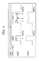
- FIG. 4 shows one example of a waveform for controlling recording power in which the front and rear edges of the pulse used for marks each having the second shortest or still longer mark length are highly energized.
- T represents a basic clock cycle
- ps represents the space length of a space just before a mark
- cm represents a recording mark length
- P 0 represents the recording power of marks each having the shortest length
- P 1 represents the recording power with an additional power added thereto for marks each having the second shortest or still longer mark length
- P 2 represents the recording power with no additional power added thereto for marks each having the second shortest and still longer mark length.
- the recording power P 0 used for marks each having the shortest mark length is set so as to be the same as the recording power P 1 of which two sites of the front and rear edges of a pulse used for marks each having the second shortest or still longer mark length.
- the recording power used for the pulse for the marks each having the second shortest or still longer mark length is set to P 2
- the value of P 1 /P 2 can be in the range of 1.10 to 2.00, however, the value of P 1 /P 2 is preferably in the range of 1.20 to 1.70.
- the period length required to highly energize the front and rear edges of pulses for the marks by adding an additional power thereto is particularly preferably in the range of 0.5 times to 2 times the basic clock cycle T i.e. in the range of 0.5T to 2T.
- the marks each having the second shortest or still longer mark length can also be recorded with a period length in the range of 0.2T to 3.0T.
- a recording power margin can be widened relative to a recording power when the recording power is controlled so as to satisfy the Expression (1).
- a recording power margin can be widened in comparison with the conventional technologies by setting optimum values of "a” and “b” in the Expression (1) to a positive number and a constant value which is independent on P 2 and by setting the values of "a” and "b” in accordance with the type of medium.
- the value P 1 varies depending on the type of recording medium, and the type of recording apparatus Generally, the type of recording apparatus greatly influences upon setting of the optimum recording power.
- the value "a” is typically set to 0.10 or less, and preferably set to around 0.01 to 0.04 ; the value “b” is typically set to 1.1 to 2.1, and preferably set to around 1.2 to 1.8, however, it is difficult to limit the values of "a” and "b” with specific numeric values because they are variable parameters depending on the type of medium.
- the set value of recording power should only be changed, and thus the recording method can be easily applied to various recording apparatuses.
- a predetermined recording method of the present invention indicates, for example, the methods which will be hereinafter described as (iv), (v), and (vi).
- high-quality recording when recording marks, high-quality recording can be achieved at high-linear velocities by irradiating the rear edges or backwards of respective pulses used for all the marks with a cooling pulse and setting the optical energy of laser irradiation to 0.1 mW or less for a given length of time.
- the optimum recording power (Pop) when recording information by the recording method of the present invention can be set according to the following methods (i) to (iii) :
- trial recording should be performed in both the inner circumferential area and outer circumferential area of the disc, and information within data storage areas should be recorded from the inner circumference toward the outer circumference while compensating the recording power P 2 by utilizing the obtained two recording powers.
- the recording power P 1 used when recording information according to the recording method of' the present invention can be obtained by assigning the value P 2 determined as described above to the Expression (1).
- the values of "a” and "b” used when recording information according to the recording method of the present invention are, as just as in the case of the optimum recording power (Pop), set by using values determined by any one of the methods of (i) Use of In-Medium Information, (ii) Set optimum recording power (Pop) based on in-medium information, and (iii) Use of value determined by trial recording.
- the value P 1 is set based on the value P 1 '.
- control information related to the values of "a” and “b” in the Expression (1) since control information related to the values of "a” and “b” in the Expression (1) has been stored in a dye-based recordable DVD medium which is intended to be recorded, and thus, when recording information, the control information can be retrieved from the dye-based recordable DVD medium to set the values of "a” and "b” with ease.
- control information may be values of "a” and “b” or may be information indicating the type of medium related to values of "a” and “b” such as name of manufacturer, the type of medium.
- information related to the information indicating values of "a” and “b” and the type of medium is stored in a storage device, and then the values of' "a” and “b” are to be retrieved from the retrieved information indicating the type of the medium. Then, the thus retrieved the values of "a” and “b” may be optimized by performing trial recording.
- preferable laser irradiation prerequisites for cooling pulses provided at rear edges or backwards of' a pulse are defined.
- the time required to irradiate the rear edge or backwards of the pulse with cooling pulses is preferably controlled to 1/6 to 6/6 as long as the shortest space length. Recording quality can be further enhanced within the range of laser irradiation time.
- information can be recorded with further lower jitter values by distinguishing the pulse width and the leading heating pulse width of a recording pulse used for forming a mark of which the space length just before the mark is the shortest depending on whether the mark length of the mark of which the space length just before the mark is the shortest or not and setting the pulse width of' a mark having the shortest mark length to be longer than the leading heating pulse width of each mark whose mark length is not the shortest (as an example, see the cases where the space length just before a mark is 3T and a recording mark length is 3T, or 4T to 14T in Table 1, which will be hereinafter described).
- information can be recorded with still further lower jitter values by distinguishing the pulse width of a recording pulse used for a mark having the shortest mark length depending on whether the space length just before the mark having the shortest mark length is the shortest or not and setting the pulse width of the mark of which the space length just before the mark is the shortest to be shorter than the pulse width of' each mark of which the space length just before the each mark is not the shortest (as an example, see the cases where a recording mark length is 3T and the space length just before the mark is 3T, or 4T to 14T in Table 1, which will be hereinafter described).
- the compensation rate (period length) required to set the leading heating pulse width to be shorter is particularly preferably in the range of 0.02T to 0.10T.
- the space length just before a mark to be formed is the shortest and the pulse width or the leading pulse width of a pulse for forming a mark of which the space length just before the mark is the shortest is substantially equal to that of each mark of which the space length just before the each mark is not the shortest, the space length just before the mark is shortened due to thermal interference, resulting in a slightly higher jitter value.
- it is effective to shorten the pulse width or the leasing heating pulse width of a pulse for forming a mark of' which the space length just before the mark is the shortest.
- the pulse width of' a pulse for forming a mark of' which the space length just before the mark is the shortest is desired to be shortened, it goes without saying that it is effective to increase the compensation rate of' a pulse or a leading heating pulse (front edge) for recording a mark of which the space length just before the mark is the shortest to thereby shorten the pulse width.
- the compensation rate (period length) used when setting the pulse width of' a mark having the shortest mark length to be longer than the leading heating pulse width of each mark whose mark length is not the shortest is preferably 0..05T to 0.25T Since it is difficult to form a mark having the shortest mark length particularly when the recording linear velocity is high, the pulse width of the mark having the shortest mark length should be compensated within the above-noted range to thereby lengthen the pulse width..
- Table 1 shows a specific example of compensation rate of a pulse width or a leading heating pulse width.
- Table 1 Mark length of a mark to be recorded 3T 4T to 14T Space length of the space just before a mark to be recorded 3T ⁇ 0.00T -0.05T 4T to 14T +0.05T ⁇ 0.00T
- optical properties As essential items for a recording layer, optical properties will be hereinafter explained.
- the optical properties of the recording layer with respect to beams at long wavelengths near wavelengths of recording and reproducing, namely, at wavelengths of recording beams and reproducing beams ⁇ 5 nm, it is preferred that a single recording layer have a refractive index "n" of 1.5 ⁇ n ⁇ 3.0 and an extinction coefficient "k" of 0.02 ⁇ k ⁇ 0.2
- n refractive index
- k extinction coefficient
- DVD-ROM is typically standardized at near the wavelength of 650 nm; the wavelength of the pulse beam for recording media is standardized at 650 to 660 nm for popular applications besides 635 nm for authoring exclusive media.
- these wavelengths are center wavelengths, namely each of' the wavelengths may be larger or smaller depending on the fluctuations at producing the semiconductor laser diode (LD).
- LDs typically tend to inherently increase the wavelength when temperature rises.
- the recording layer in the present invention is applicable within the wavelength region of 600 nm to 720 nm which includes the range described above.
- the basic clock cycle T for determining the wobble frequency is about 0.133 ⁇ m or about 38 nsec in the case of 4.7 GB DVD media.
- a basic clock cycle corresponding to 150T to 400T is used for the frequency band of wobble.
- the frequency band may not be suitable for high density recording when data is added to be recorded by frequency modulation or phase modulation since significant spaces inevitably exist between the previous data and the data to be additionally recorded.
- LPP is provided with recordable DVD-R, and the sites to be recorded with data are controlled by the LPP signals.
- the optimum signal amplitude is limited to 0.16 ⁇ LPPb ⁇ 0.32 in LPP and preferably 0.18 ⁇ LPPb ⁇ 0.26 in LPP. Accordingly, the cut width of' lands should be controlled precisely at preparing the stamper.
- the preferred frequency of the high-frequency wobble is 4T to 96T.
- the detection is likely to be difficult due to excessively low frequency, and the reliability as to rotation control and address detection may be insufficient
- the wobble frequency is more than 96T, the space intervals between additionally recorded data is excessively wide, resulting in a reduced capacity or an insufficient data processing speed.
- the wobble amplitude of the recordable DVD media in the present invention when the ratio of wobble amplitude Wo after passing through appropriate filters such as high filter at 4 MHz and low filter at 30 kHz to push-pull amplitude PP after passing through a filter at 30 kHz, i.e. Wo/PP, satisfies the relation 0.1 ⁇ Wo/PP ⁇ 0.4, the synchronization is relatively easy, and is preferably 0.15 ⁇ Wo/PP ⁇ 0.3.
- the LPP type requires precise cut width control in order to adjust the LPP cut width into 0.16 to 0..32, whereas the wobble type in the present invention requires no more than the control of high-frequency source and swing level of a wobble (the swing level of the wobble can be arbitrarily controlled to gain excellent reproducibility in the circuit to control the swing level), therefore, the yields of stampers and DVD media can be increased remarkably,
- the groove depth is preferably 1,000 angstroms to 2,500 angstroms, and more preferably 1,500 angstroms to 2,000 angstroms in the case that recording layers are formed using an organic dye by solvent coating processes.
- the groove depth is less than 1,000 angstroms, the tracking may not be controlled appropriately due to insufficient push-pull signals, and then the grove depth is more than 2,500 angstroms, it is unfavorable because the transferring ability may be deteriorated at molding substrates.
- the dye groove depth d1 when a dye recording layer is provided the following relation is preferable : 1 , 200 ⁇ d ⁇ 1 ⁇ m ⁇ 160 , 000 where mT: wobble frequency (m: natural number)
- mT wobble frequency (m: natural number)
- (d1 x m) is less than 1,200, the differential signals are insufficient, the tracking may not be performed appropriately at recording and reproducing, and when (d1 x m) is more than 160,000, oscillation may be induced that may adversely effect on the tracking.
- the groove depth of substrates are typically limited by the transferring limit due to the substrate molding described above, thus the groove depth is limited to 160,000 or less in practice.
- the pitch of tracks is typically required to be 0.64 ⁇ m to 0.8 ⁇ m in order to assure the recording density of' 4GB to 5 GB.
- the groove width depends on the recording material in general; usually the half-width is 0.18 ⁇ m to 0.40 ⁇ m in almost all organic materials.
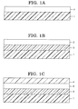
- FIGS. 1A to 1D exemplarily show a layer structure of a conventional recordable optical disc, respectively
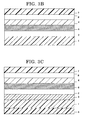
- FIGS. 2A to 2C exemplarily show a layer structure of a conventional CD-R medium, respectively
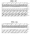
- FIGS. 3A to 3C exemplarity show a layer structure of a recordable DVD medium, respectively.
- the dye-based recordable DVD medium of the present invention preferably has a basic layer structure in which a first substrate and a second substrate (or protective substrate) are bonded with an adhesive so as to sandwich a recording layer therebetween, as shown in FIGS. 3B and 3C .
- a substrate is indicated by reference numeral 1; a recording layer is indicated by reference numeral 2; an undercoat layer is indicated by reference numeral 3; a protective layer is indicated by reference numeral 4; a hard-coat layer is indicated by reference numeral 5; a metal reflective layer is indicated by reference numeral 6; a protective substrate is indicated by reference numeral 7; and an adhesive layer is indicated by reference numeral 8.
- the recording layer 2 may be a single organic dye layer or may be formed in a laminar structure of an organic dye layer and a reflective layer for increasing the reflectance.
- the undercoat layer 3 or the protective layer 4 may be formed between the recording layer 2 and the substrate 1, and in order to enhance properties of a recordable optical medium, each of the individual layers may be formed with two or more layers in a laminar structure.
- the most commonly used layer structure is composed of a first substrate, an organic dye layer, a reflective layer, a protective layer, an adhesive layer, and a second substrate (protective substrate).
- the substrate When recording and/or reproducing is performed from the substrate side, the substrate must be transparent to laser beams, however, when recording and/or reproducing is performed from the recording layer side, the substrate is not necessarily transparent to laser beams.
- materials available for the substrate include plastics such as polyester resins, acrylic resins, polyamide resins, polycarbonate resins, polyolefin resins, phenol resins, epoxy resins, and polyimide resins; glasses, ceramics, and metals.
- a guide groove or a guide pit for tracking, and a preformat such as address signals may be formed.
- land prepit method is used for DVD-R/RW discs
- high-frequency wobble method is used for DVD+R/RW discs. In both of the methods, disc information and address information is input in discs, and a recording drive can perform recording based on the information.
- the main component means that an organic dye in a sufficient amount for recording and reproducing information is contained, and typically, only an organic dye or organic dyes are used except for a small amount of additives to be suitably added in accordance with the necessity.
- organic dyes examples include azo dyes, formazan dyes, dipyrromethene dyes, (poly)methyne dyes, naphtalocyanine dyes, phthalocyanine dyes, tetraazaporphyrin dyes, squarylium dyes, chloconium dyes, pyrylium dyes, naphthoquinone dyes, anthraquinone dyes (indanthrene dyes), xanthene dyes, triphenylmethane dyes, azulene dyes, tetrahydrocoline dyes, phenanthrene dyes, triphenothiazine dyes, and metal complexes thereof.
- azo(metalchelate) dyes formazan(metalchelate) dyes, squarylium(metalchelate) dyes, dipyrromethene(metalchelate) dyes, trimethynecyanine dyes, tetraazaporphyrin dyes, and metal complexes thereof are preferable.
- the initial decomposition temperature or kick-off temperature is preferably 100°C to 360°C, and particularly preferably 100°C to 350°C.
- the kick-off temperature is more than 360°C, the pits may not formed successfully, thus the jitter value will be higher, and when the kick-off temperature is less than 100°C, the storage stability degrades.
- the dyes described above may be added with other organic dyes, metals, and/or metal compounds in order to improve the optical properties, recording sensitivity and/or signal properties, or a dye-layer and a layer containing other organic dyes, metals, and/or metal compounds may be formed as a recording layer in a laminar structure.
- additional metals and metal compounds include In, Te, Bi, Se, Sb, Ge, Sn, Al, Be, TeO 2 , SnO, As and Cd. Each of these metals and metal compounds may be dispersed and mixed for use.
- polymer materials such as ionomer resins, polyamide resins, vinyl resins, natural polymers, silicones, and liquid rubbers
- silane coupling agents may be dispersed and mixed, or for the purpose of' improving properties
- stabilizers such as transition metal complexes, dispersing agents, flame-retardants, lubricants, antistatic agents, surfactants, and plasticizers may be used along with the dye materials
- the recording layer may be formed by conventional methods such as vapor deposition method, sputtering method, CVD method, and coating method.
- the coating method may be carried out by dissolving materials described above in an organic solvent to form a coating liquid, then the coating liquid is processed by conventional coating method such as spray coating, roller coating, dip coating, and spin coating.
- organic solvent for use examples include alcohols such as methanol, ethanol, and isopropanol; ketones such as acetone, methyl ethyl ketone, and cyclohexanone; amides such as N,N-dimethylformamide and N,N-dimethylacetamide; sulfoxide such as dimethylsulfoxide; ethers such as tetrahydrofuran, dioxane, diethylether, and ethyleneglycol monomethylether; esters such as methyl acetate and ethyl acetate; halogenated hydrocarbons such as chloroform, methylene chloride, dichloroethane, carbon tetrachloride, and trichloroethane; aromatics such as benzene, xylene, monochlorobenzene, and dichlorobenzene; cellosolve such as methoxy ethanol, ethoxy ethanol; and hydrocarbons such as hexane
- the thickness of' the recording layer is appropriately 100 angstroms to 10 ⁇ m, and preferably 200 angstroms to 2,000 angstroms .
- the undercoat layer is disposed for the purposes of (1) improving the adhesion, (2) serving as a barrier layer against water or gases, (3) improving the shelf life of the recording layer, (4) improving the reflectivity of the recording layer, (5) protecting the substrate from solvents, and/or (6) forming guide grooves, guide pits, pre-formats, and the like.
- various polymer compounds such as ionomer resins, polyamide resins, vinyl resins, natural resins, natural polymers, silicones, and liquid rubbers, and silane coupling agents may be employed.
- inorganic compounds such as SiO, MgF, SiO 2 , TiO, ZnO, TiN, and SiN can be used in addition to the above-described polymer materials. Further, metals and semimetals such as Zn, Cu, Ni, Cr, Ge, Se, Au, Ag, and Al can be used. To attain the purpose (4), metals such as Al, Au and Ag, and organic thin films having a metal luster such as methine dye and xanthene dye may be used. To attain the purposes (5) and (6), an ultraviolet curable resin, a thermosetting resin, and a thermoplastic resin can be used.
- the thickness of the undercoat layer may be properly selected depending on the application; preferably, the thickness is 0.01 ⁇ m to 30 ⁇ m, and more preferably 0.05 ⁇ m to 10 ⁇ m.
- Examples of materials of the reflective layer include metals and semimetals exhibiting high reflectivity corrosion resistance such as Au, Ag, Cr, Ni, Al, Fe, and Sn. Among these metals, Au, Ag, and Al are particularly preferred in view of the reflectivity and the productivity. These metals and semimetals may be used alone or in combination of two or more as an alloy..
- the reflective layer may be formed by deposition, sputtering or the like
- the thickness of the reflective layer is typically 50 angstroms to 5,000 angstroms, and preferably 100 angstroms to 3,000 angstroms..
- the protective layer and the hard coat layer on the substrate surface may be provided in order to (1) protect the recording layer or the reflection absorbing layer from scratches, dust, and contamination, (2) improve the shelf life of the recording layer or the reflection absorbing layer, and (3) improve the reflectivity" To satisfy these purposes, materials similar to those used for the undercoat layer may be used.
- thermoplastic materials thermosetting materials, and UV curable resins
- organic materials of thermoplastic materials, thermosetting materials, and UV curable resins are available such as polymethacrylate resins, polycarbonate resins, epoxy resins, polystyrene resins, polyester resins, cellulose resins, aliphatic hydrocarbon resins, aromatic hydrocarbon resins, natural rubber, styrene-butadiene resins, chloroprene rubbers, waxes, alkyd resins, drying oils, and rosins.
- UV curable resins are preferable from the view point of the superiority of productivity.
- the thickness of the protective layer or the hard coat layer is typically 0,01 ⁇ m to 30 ⁇ m, and preferably 0.05 ⁇ m to 10 ⁇ m.
- the protective layer or the hard coat layer on the substrate surface may contain stabilizers, dispersing agents, flame-retardants, lubricants, antistatic agents, surfactants, and plasticizers as is the case with the recording layer. « Protective Substrate»
- the protective substrate is required to be transparent to laser beams when the laser beam is applied through the substrate, however, when the protective substrate is used for protective purpose, the transparency is not required
- the materials for the protective substrate are utterly the same as those for the substrate; for example, plastics such as polyesters, acrylic resins, polyamides, polycarbonate resins, polyolefin resins, phenol resins, epoxy resins, and polyimides; glass, ceramics, metals, and the like may be used,
- the material of the adhesive layer may be suitably selected, provided that the two recording media can be bonded together, and the material of the adhesive layer is selected from UV curable adhesives and hot-melt adhesives in consideration of productivity.
- Optical discs are used as media for storing a large amount of information, typically, information is recorded on and reproduced from an optical disc by an optical disc drive or a recording and reproducing apparatus.
- configuration of optical discs and optical disc drives will be outlined.
- DVD-RAM Wo, DVD-R, DVD + R, and DVD-RAM, DVD-RW, and DVD + RW discs are recordable DVD (Digital Versatile Discs).
- DVD-RAM Wo, DVD-R, and DVD + R discs are DVD capable of' recording only once, which are referred to as DVD Write Once.
- DVD-RAM, DVD-RW, and DVD + RW discs are DVD capable of recording more than once.
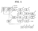
- Optical discs such as DVD + R and DVD + RW, information is recorded and reproduced by an optical disc drive as shown in FIG.. 5 .
- FIG.. 5 is a block diagram exemplarily showing core parts of an optical disc drive.
- the optical disc drive shown in FIG. 5 includes an optical disc 11, a spindle motor 12, an optical pickup 13, a motor driver 14, a read amplifier 15, a servo unit 16, a DVD decoder 17, an ADIP decoder 18, a laser controller 19, a DVD encoder 20, a DVD-ROM encoder 21, a buffer RAM 22, a buffer manager 23, a DVD-ROM decoder 24, an ATAPI/SCSI interface 25, a D/A converter 26, a ROM 27, a CPU 28, and a RAM 29.
- LB represents a laser beam
- Audio represents audio output signals.
- the arrow marks indicate the main direction of data flow.
- the CPU 28 that controls the respective blocks in FIG. 5 is expressed by removing the connections with the respective blocks using only wide lines.
- the ROM 27 a control program written in codes that can be decoded by the CPU 28 is stored.
- the program is loaded on a main memory (not shown), the CPU 28 controls the respective parts in accordance with the program and stores necessary data to control into the RAM 29 temporarily.
- the structure and operations of' the optical disc drive are as follows.
- the optical disc 11 is driven to rotate by the spindle motor 12.
- the spindle motor 12 is controlled by the motor driver 14 and the servo unit 16 so as to a regular linear velocity or a regular angular velocity can be kept.
- the linear velocity or the angular velocity may be changed step-wise.
- the optical pickup 13 incorporates a semiconductor laser, optical system, focus actuator, track actuator, receiving optics, and position sensor (not shown respectively), and irradiates laser beam LB onto the optical disc 11.
- the optical pickup 13 can be moved in a sledge direction by a seek motor.
- These focus actuator, track actuator and seek motor are controlled by the motor driver 14 and the servo unit 16 based on the signals from the receiving optics and the position sensor so as to situate the spot of laser beam LB on the intended site of the optical disc 11.
- reproducing signals obtained by the optical pickup 13 are amplified and binarized by the read amplifier 15, and input into the DVD decoder 17.
- the input and binarized data is demodulated by 8/16 at the DVD decoder 17.
- the recording data is bundled by every 8 bits and modulated to 8/16 modulation, and 8 bits are transformed into 16 bits in the modulation.
- the combined bits are assigned such that the prior numbers of "1" and "0" are equal when averaged, which is referred to as "suppression of DC component" wherein the fluctuation of slice level of DC cut regeneration signals is suppressed.
- the demodulated data is processed with respect to deinterleave and error collection. Then the data is input into the DVD-ROM decoder 24, and further processed with respect to error correction so as to enhance the data reliability.
- the data subjected to two times of error correction is stored once at the buffer RAM 22 by means of the buffer manager 23, and transferred to a host computer (not shown) at a time through the ATAPI/SCSI interface 25 in a state that is collected as sector data.
- the data output from the DVD decoder 17 is input to the D/A converter 26 and then is taken out as audio output signals Audio of analog data.
- the data sent from the host computer through the ATAPI/SCSI interface 25 is stored at the buffer RAM 22 by means of the buffer manager 23 once. Then, the writing operation starts; before the writing operation, the laser spot is required to be positioned at the writing initiating site.
- the site is determined from wobble signals which are previously recorded with slightly sinusoidal waves of tracks on the optical disc 11 in the case of DVD+RW/+R.
- the site is determined by land pre-pits in the case of DVD-RW/-R, by pre-pits in the case of DVD-RW/RAM WO in place of wobble signals.
- the wobble signals in DVD RW/+R discs contain address information of so-called ADIP (ADress In Pre-groove), and the address information is retrieved by the ADIP decoder 18.
- ADIP Address In Pre-groove
- the synchronous signals generated by the ADIP decoder 18 are input to the DVD encoder 20, which enables to write data at correct sites on the optical disc 11.
- the data stored in the buffer RAM 22 is subjected to addition of error correction code and/or an interleaving operation by the DVD-ROM encoder 21 and/or the DVD encoder 20, then is recorded into the optical disc 11 by the use of a recording waveform according to the present invention through the laser controller 19 and the optical pickup 13.
- Another aspect of the recording apparatus of the present invention is equipped with a first recording unit configured to record shortest marks on a recording layer primarily containing an organic dye, which is farmed on a substrate having a guide groove with a wobble formed on a surface thereof, by the use of a simple rectangular wave pulse; a second recording unit configured to record marks each having the second shortest or still longer mark length by the use of one pulse of' which two sites of the front and rear edges are highly energized for a given length of time; a cooling pulse irradiation optical energy controlling unit configured to control the optical energy for irradiating the rear edge or backwards of the one pulse with a cooling pulse so as to be 0.1 mW or less for a given length of time; a laser beam irradiation unit configured to irradiate a pulse used for recording marks with a laser beam; a pulse outputting unit configured to set recording powers of P 1 and P 2 and output a pulse to the laser beam irradiation unit based on the set recording powers of P
- the laser controller 19 receives signals from the DVD encoder 20 shown in FIG. 5 , the recording powers P 1 and P 2 controlled for information of respective signals are set in the laser controller 19, and then a recording waveform according to the present invention is output through the optical pickup 13
- the laser beam irradiation unit is primarily composed of the optical pickup 13;
- the pulse outputting unit is primarily composed of the laser controller 19;
- the storing unit is composed of the ROM 27; and
- the controlling unit is primarily composed of the DVD encoder 20 and the CPU 28.
- the recording apparatus for dye-based recordable DVD medium of the present invention is further equipped with a retrieving unit configured to retrieve control information related to the values "a” and “b” in the Expression (1) from a dye-based recordable DVD medium in which the control information has been stored, and the controlling unit is configured to control and set the values of "a” and "b” in the Expression (1) based on the retrieved control information.
- the retrieving unit is configured to retrieve the control information just as in the case of reading of reproducing signals as described above.
- controlling unit is configured to control the pulse outputting unit such that the time required to irradiate the rear edges or backwards of respective pulses with the cooling pulse can be 1/6 to 6/6 as long as the shortest space length.
- the controlling unit is configured to control a pulse outputting unit such that the pulse width of a mark having the shortest mark length is set to be longer than the leading heating pulse width of each mark whose mark length is not the shortest by distinguishing the pulse width and the leading heating pulse width of a recording pulse for forming a mark of which the space length just before the mark is the shortest depending on whether the mark length of the mark of which the space length just before the mark is the shortest is the shortest or not; and the pulse width of the mark of which the space length just before the mark is the shortest is set to be shorter than the pulse width of each mark of which the space length just before the each mark is not the shortest by distinguishing the pulse width of a recording pulse for forming the mark having the shortest mark length depending on whether the space length just before the mark having the shortest mark length is the shortest is the shortest or not.
- the recording apparatus of the present invention allows for achieving high-quality recording, i.e., low-jitter property.
- a method of retrieving address information from a land prepit or a prepit may be employed.
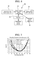
- FIG. 6 is a view schematically showing an information processing unit utilizing the optical disc drive shown in FIG. 5 .
- Information processing unit 50 is equipped with main control device 51, interface 52, recording device 53, input device 54, and display device 55, and the like.
- the main control device 51 is structured from a CPU (central processing unit, micro computer), main memory, and the like (respectively not shown), and controls the entire host computer thereby.
- Interface 52 is a communication interface interactive with optical disc drive, and is based on standard interfaces such as ATAPI and CSI.
- the interface 52 is connected to interface 25 of the optical disc drive described above.
- the connection between the respective interfaces may be not only cable connection by means of communication line or cable such as SCSI cable but also wireless connection utilizing infrared ray for example.
- Information recording device 53 (HDD, hard disc) is equipped with a program written by cords readable by the microcomputer of the main control device 51. When the driving power source of' the information processing unit is turned on, the program is loaded on the main memory of the main control device 51..
- the display device 55 is equipped with a displaying portion (not shown) such as a CRT, liquid crystal display (LCD), and plasma display panel (PDP), and displays various information from the control device 51.
- the input device 54 is equipped with at least one input medium (not shown) such as a keyboard, mouse, and pointing device, and informs the main control device 51 of a variety of information input by users. Information from the input media may be input by means of wireless connection
- the information processing unit is equipped with an operating system (OS) All of the devices constituting the information processing unit 50 are controlled by the operating system.
- OS operating system
- a polycarbonate substrate formed by an injection molding having the following configuration was prepared. Groove depth of 1,670 angstroms, half' value width of 0.39 ⁇ m, track pitch of 0.74 ⁇ m, wobble frequency corresponding to 32T, thickness of 0.6 mm, and outside diameter of 120 mm.
- a dye compound 1 represented by the following Structural Formula 1 and a dye compound 2 represented by the following Structural Formula 2 were weighed and employed with a weight ratio of 75:25 and then dissolved in a solvent of 2,2,3,3-tetrafluoro-1-propanol
- the solution of the dye compounds was applied over a surface of the polycarbonate substrate by a spinner coating method, thereby forming an organic dye layer having a thickness of 750 angstroms on the substrate. Then, the organic dye layer was dried at 90°C for 30 minutes.
- a reflective layer made ofAg having a thickness of 1,100 angstroms was formed on the organic dye layer by a sputtering method, a protective layer made of acrylic photopolymer having a thickness of 5 ⁇ m was further formed on the reflective layer, and then a flat polycarbonate substrate having a thickness of 0.6 mm and an outside diameter of 120 mm prepared by an injection molding method was bonded to the protective layer using an acrylic photopolymer to thereby prepare an optical recording medium.
- the waveform used for the laser beam in the recording is as shown in FIG. 4 . Since the recording power P 2 depends on the type of optical recording medium and the type of recording and reproducing apparatus, the recording power P 2 was set to a recording power by which the jitter value was minimum (optimum recording power).
- the recording powers of P 0 and P 1 were set to the same value, the optical energy for irradiation of cooling pulse was set to 0..0 mW; and the recording linear velocity was set to 27.9 m/s (recording speed at 8X)
- FIG. 7 shows the measurement results of the recording properties of the respective optical recording media.
- the measurement results verified that in the optical recording medium of Examples 1 to 3, the recording power margin (allowable recording power range) was widened as compared to the optical recording media prepared based on conventional technologies.
- optical recording media of Examples 4 to 7 and Comparative Examples 2 to 4 were evaluated in the same recording conditions as in Examples 1 to 3 except that the optical energy for irradiation of cooling pulse and the pulse width were changed as described in Table 3.
- Table 3 also shows the respective jitter values obtained at the optimum recording power.
- Table 4 shows the measurement results. The values (%) shown in Table 4 are jitter values when recording the signals at a recording speed of 12X with the optimum recording power.
- recording power along the horizontal scale shown in FIG. 8 is the recording power of "P 1 ".
Landscapes
- Optical Recording Or Reproduction (AREA)
- Optical Head (AREA)
- Optical Record Carriers And Manufacture Thereof (AREA)
Claims (18)
- Aufzeichnungsverfahren für ein auf Farbstoff basierendes aufzeichnungsfähiges DVD-Medium, umfassend:das Aufzeichnen kürzester Markierungen auf eine Aufzeichnungsschicht, die hauptsächlich einen organischen Farbstoff enthält und auf einem Substrat gebildet ist, das eine Führungsrille mit einem Wobbel aufweist, die auf der Oberfläche davon gebildet ist,das Aufzeichnen von Markierungen, die jeweils die zweitkürzeste oder noch längere Markierungslängen aufweisen, durch die Verwendung von einem Puls, von dem zwei Stellen der vorderen und hinteren Ränder für eine gegebene Zeitspanne stark energetisiert sind unddas Steuern der optischen Energie zum Bestrahlen des hinteren Rands oder des hinteren Teils des einen Pulses mit einem Kühlpuls, um für einen gegebenen Zeitraum 0,1 mW oder weniger zu sein, dadurch gekennzeichnet, dassdie kürzesten Markierungen durch die Verwendung eines einfachen Rechteckwellenpulses aufgezeichnet werden,und, wenn die Aufzeichnungsenergie der vorderen und hinteren Ränder des Pulses, der für die Markierungen verwendet wird, die jeweils die zweitkürzeste oder noch längere Markierungslängen aufweisen, durch P1 dargestellt ist und die Aufzeichnungsenergie des Zwischenpulses zwischen dem vorderen Rand des Pulses und dem hinteren Rand des Pulses durch P2 dargestellt ist, Markierungen aufgezeichnet werden, während die Aufzeichnungsenergie P2 gemäß einer bestimmten Steuerstrategie gesteuert wird und die Aufzeichnungsenergie P1 gesteuert wird, so dass der Wert von P1/P2 eingestellt wird, damit er ein größerer Wert ist, vorausgesetzt dass die Aufzeichnungsenergie P1 eine niedrige Energie ist, und der Wert von P1/P2 eingestellt wird, damit er ein kleinerer Wert ist, vorausgesetzt dass die Aufzeichnungsenergie P1 eine hohe Energie ist, wobei Markierungen aufgezeichnet werden, während die Aufzeichnungsenergie P2 gemäß einer bestimmten Steuerstrategie gesteuert wird und die Aufzeichnungsenergie P1 auf Basis von P1' gesteuert wird, die abgeleitet ist aus der folgenden Gleichung (1) unter Verwendung der energiegesteuerten Aufzeichnungsenergie P2,worin "a" und "b" jeweils eine positive Zahl sind.

- Aufzeichnungsverfahren für ein auf Farbstoff basierendes aufzeichnungsfähiges DVD-Medium nach Anspruch 1, wobei die Werte für "a" und "b" in der Gleichung (1) in einem auf Farbstoff basierenden aufzeichnungsfähigen DVD-Medium auf Basis von Steuerinformationen, die von dem auf Farbstoff basierenden aufzeichnungsfähigen DVD-Medium abgerufen werden, in dem die Steuerinformationen gespeichert worden sind, eingestellt werden.
- Aufzeichnungsverfahren für ein auf Farbstoff basierendes aufzeichnungsfähiges DVD-Medium nach irgendeinem der Ansprüche 1 und 2, wobei die erforderliche Zeit für die Bestrahlung der hinteren Ränder oder der hinteren Teile der betreffenden Pulse mit dem Kühlpuls gesteuert wird, um 1/6 bis 6/6 so lang wie die kürzeste Raumlänge zu sein.
- Aufzeichnungsverfahren für ein auf Farbstoff basierendes aufzeichnungsfähiges DVD-Medium nach irgendeinem der Ansprüche 1 bis 3, wobei die Pulsbreite und die führende Heizpulsbreite eines Aufzeichnungspulses zur Bildung einer Markierung, deren Raumlänge gerade vor der Markierung die kürzeste ist, in Abhängigkeit davon, ob die Markierungslänge der Markierung, deren Raumlänge gerade vor der Markierung die kürzeste ist, die kürzeste ist oder nicht, unterschieden werden, um dadurch die Pulsbreite einer Markierung mit der kürzesten Markierungslänge einzustellen, damit sie länger ist als die führende Heizpulsbreite von jeder Markierung, deren Markierungslänge nicht die kürzeste ist; und die Pulsbreite eines Aufzeichnungspulses zur Bildung der Markierung mit der kürzesten Markierungslänge in Abhängigkeit davon, ob die Raumlänge gerade vor der Markierung mit der kürzesten Markierungslänge die kürzeste ist oder nicht, unterschieden wird, um dadurch die Pulsbreite der Markierung, deren Raumlänge gerade vor der Markierung die kürzeste ist, einzustellen, damit sie kürzer ist als die Pulsbreite von jeder Markierung, deren Raumlänge gerade vor der Markierung nicht die kürzeste ist.
- Aufzeichnungsverfahren für ein auf Farbstoff basierendes aufzeichnungsfähiges DVD-Medium nach irgendeinem der Ansprüche 1 bis 4, wobei die Wobbelfrequenz eine Frequenz ist, die 4T bis 96T entspricht, wenn der Basistaktzyklus durch T repräsentiert ist.
- Aufzeichnungsverfahren für ein auf Farbstoff basierendes aufzeichnungfähiges DVD-Medium nach irgendeinem der Ansprüche 1 bis 5, bei dem die Wobbelamplitude (Wo) mit der Push-Pull-Amplitude (PP) eines Spurfehler-Detektionssignals zur Detektion und Steuerung von Spurfehlern unter Verwendung eines dualen Photodetektors synchronisiert wird, so dass das Verhältnis Wo/PP im Bereich von 0,1 ≤ Wo/PP ≤ 0,4 liegt.
- Aufzeichnungsverfahren für ein auf Farbstoff basierendes aufzeichnungsfähiges DVD-Medium nach irgendeinem der Ansprüche 1 bis 6, bei dem die Wellenlänge des Aufzeichnungslichtstrahls 600 nm bis 720 nm beträgt.
- Aufzeichnungsverfahren für ein auf Farbstoff basierendes aufzeichnungsfähiges DVD-Medium nach irgendeinem der Ansprüche 1 bis 7, bei dem der Brechungsindex "n" und der Extinktionskoeffizient "k" einer einschichtigen Aufzeichnungsschicht in den Bereichen von 1,5 ≤ n ≤ 3,0 bzw. 0,02 ≤ k ≤ 0,2 relativ zu einem Lichtstrahl im Wellenlängenbereich der Wellenlänge des Lichtstrahls ± 5 nm sind.
- Aufzeichnungsverfahren für ein auf Farbstoff basierendes aufzeichnungsfähiges DVD-Medium nach irgendeinem der Ansprüche 1 bis 8, bei dem die anfängliche Zersetzungstemperatur der Aufzeichnungsschicht 100°C bis 360°C ist.
- Aufzeichnungsverfahren für ein auf Farbstoff basierendes aufzeichnungsfähiges DVD-Medium nach irgendeinem der Ansprüche 1 bis 9, bei dem das auf Farbstoff basierende aufzeichnungsfähige DVD-Medium ferner mindestens eine ausgewählt aus einer Reflexionsschicht, einer Schutzschicht, einer Klebschicht, einem Schutzsubstrat und einer Hartschicht, die auf einem Substrat mit der Führungsrille mit dem Wobbel gebildet auf der Oberfläche davon gebildet sind, umfasst.
- Aufzeichnungsverfahren für ein auf Farbstoff basierendes aufzeichnungsfähiges DVD-Medium nach Anspruch 10, bei dem die Reflexionsschicht irgendeines von Au, Ag und Al oder einer Legierung enthaltend mindestens irgendeines von Au, Ag und Al als Hauptkomponente umfasst.
- Aufzeichnungsverfahren für ein auf Farbstoff basierendes aufzeichnungsfähiges DVD-Medium nach irgendeinem der Ansprüche 10 bis 11, bei dem die Schutzschicht ein Ultraviolett-härtbares Harz umfasst.
- Aufzeichnungsverfahren für ein auf Farbstoff basierendes aufzeichnungsfähiges DVD-Medium nach irgendeinem der Ansprüche 10 bis 12, bei dem die Klebschicht sandwichartig zwischen zwei Substraten angeordnet ist, so dass ein Aufzeichnungsmedium mit zwei Substraten gebildet wird, und ein Klebstoff, der für die Klebschicht verwendet wird, ein Ultraviolett-härtbares Harz ist.
- Aufzeichnungsvorrichtung für ein auf Farbstoff basierendes aufzeichnungsfähiges DVD-Medium, umfassend:eine erste Aufzeichnungseinheit, die konfiguriert ist, um kürzeste Markierungen auf eine Aufzeichnungsschicht, die hauptsächlich einen organischen Farbstoff enthält und auf einem Substrat gebildet ist, das eine Führungsrille mit einem Wobbel aufweist, die auf der Oberfläche davon gebildet ist, aufzuzeichnen,eine zweite Aufzeichnungseinheit, die konfiguriert ist, um Markierungen, die jeweils die zweitkürzeste oder noch längere Markierungslängen aufweisen, durch die Verwendung von einem Puls, von dem zwei Stellen der vorderen und hinteren Ränder für eine gegebene Zeitspanne stark energetisiert sind, aufzuzeichnen,eine optische Kühlpulsbestrahlungsenergie-Steuereinheit, die konfiguriert ist, um die optische Energie zum Bestrahlen des hinteren Rands oder des hinteren Teils des einen Pulses mit einem Kühlpuls zu steuern, um für einen gegebenen Zeitraum 0,1 mW oder weniger zu sein,eine Laserbestrahlungseinheit, die konfiguriert ist, um einen Puls auszustrahlen, der zur Aufzeichnung von Markierungen mit einem Laserstrahl verwendet wird,eine Pulsausgabeeinheit, die konfiguriert ist, um Aufzeichnungsenergien P1 und P2 einzustellen und einen Puls zur Laserbestrahlungseinheit auf Basis der eingestellten Aufzeichnungsenergien von P1 und P2 auszugeben, wenn die Aufzeichnungsenergie der vorderen und hinteren Ränder des Pulses, der für die Markierungen verwendet wird, die jeweils die zweitkürzeste oder noch längere Markierungslängen aufweisen, durch P1 dargestellt ist und die Aufzeichnungsenergie des Zwischenpulses zwischen dem vorderen Rand des Pulses und dem hinteren Rand des Pulses durch P2 dargestellt ist, undeine Steuereinheit, die konfiguriert ist, um die Pulsausgabeeinheit zu steuern, dadurch gekennzeichnet, dassdie erste Aufzeichnungseinheit konfiguriert ist, um die kürzesten Markierungen durch die Verwendung eines einfachen Rechteckwellenpulses aufzuzeichnen,die Steuereinheit konfiguriert ist, um die Pulsausgabeeinheit zu steuern, so dass die Aufzeichnungsenergie P2 gemäß einer bestimmten Steuerstrategie eingestellt wird und die Aufzeichnungsenergie P1 eingestellt wird, so dass der Wert von P1/P2 eingestellt wird, damit er ein größerer Wert ist, vorausgesetzt dass die Aufzeichnungsenergie P1 eine niedrige Energie ist, und der Wert von P1/P2 eingestellt wird, damit er ein kleinerer Wert ist, vorausgesetzt dass die Aufzeichnungsenergie P1 eine hohe Energie ist, und wobei die Aufzeichnungsvorrichtung ferner eine Speichereinheit umfasst, die konfiguriert ist, um die folgende Gleichung (1) zu speichern, wobei die Steuereinheit konfiguriert ist, um den Wert der gesteuerten Aufzeichnungsenergie P2 der folgenden Gleichung (1) zuzuordnen, die von der Speichereinheit gelesen wurde, um dadurch eine Aufzeichnungsenergie P1' auszurechnen; und die Pulsausgabeeinheit konfiguriert ist, um die Aufzeichnungsenergie P1 auf Basis der berechneten Aufzeichnungsenergie P1' einzustellen,worin "a" und "b" jeweils eine positive Zahl sind.

- Aufzeichnungsvorrichtung für ein auf Farbstoff basierendes aufzeichnungsfähiges DVD-Medium nach Anspruch 16, ferner umfassend eine Abfrageeinheit, die konfiguriert ist, um Steuerinformationen bezüglich der Werte von "a" und "b" in der Gleichung (1) von einem auf Farbstoff basierenden aufzeichnungsfähigen DVD-Medium, in dem die Steuerinformationen gespeichert worden sind, abzurufen, wobei die Steuereinheit konfiguriert ist, um die Werte von "a" und "b" auf Basis der abgefragten Steuerinformationen einzustellen.
- Aufzeichnungsvorrichtung für ein auf Farbstoff basierendes aufzeichnungsfähiges DVD-Medium nach irgendeinem der Ansprüche 14 bis 15, wobei die Steuereinheit konfiguriert ist, um die Pulsausgabeeinheit zu steuern, so dass die erforderliche Zeit für die Bestrahlung der hinteren Ränder oder der hinteren Teile der betreffenden Pulse mit dem Kühlpuls 1/6 bis 6/6 so lang wie die kürzeste Raumlänge ist.
- Aufzeichnungsvorrichtung für ein auf Farbstoff basierendes aufzeichnungsfähiges DVD-Medium nach irgendeinem der Ansprüche 14 bis 16, wobei die Steuereinheit konfiguriert ist, um die Pulsbreite einer Markierung mit der kürzesten Markierungslänge einzustellen, damit sie länger ist als die führende Heizpulsbreite von jeder Markierung, deren Markierungslänge nicht die kürzeste ist, durch Unterscheidung der Pulsbreite und der führenden Heizpulsbreite eines Aufzeichnungspulses zur Bildung einer Markierung, deren Raumlänge gerade vor der Markierung die kürzeste ist, in Abhängigkeit davon, ob die Markierungslänge der Markierung, deren Raumlänge gerade vor der Markierung die kürzeste ist oder nicht; und um die Pulsbreite der Markierung, deren Raumlänge gerade vor der Markierung die kürzeste ist, einzustellen, damit sie kürzer ist als die Pulsbreite von jeder Markierung, deren Raumlänge gerade vor der Markierung nicht die kürzeste ist, durch Unterscheidung der Pulsbreite eines Aufzeichnungspulses zur Bildung der Markierung mit der kürzesten Markierungslänge in Abhängigkeit davon, ob die Raumlänge gerade vor der Markierung mit der kürzesten Markierungslänge die kürzeste ist oder nicht.
- Auf Farbstoff basierendes aufzeichnungsfähiges DVD-Medium, vorformatiert mit Information, um ein Aufzeichnungsverfahren für ein auf Farbstoff basierendes aufzeichnungsfähiges DVD-Medium nach irgendeinem der Ansprüche 1 bis 4 durchzuführen.
Applications Claiming Priority (2)
| Application Number | Priority Date | Filing Date | Title |
|---|---|---|---|
| JP2006044944 | 2006-02-22 | ||
| JP2007018055A JP2007257819A (ja) | 2006-02-22 | 2007-01-29 | 色素系追記型dvd媒体の記録方法及び装置 |
Publications (2)
| Publication Number | Publication Date |
|---|---|
| EP1826751A1 EP1826751A1 (de) | 2007-08-29 |
| EP1826751B1 true EP1826751B1 (de) | 2008-11-12 |
Family
ID=37945033
Family Applications (1)
| Application Number | Title | Priority Date | Filing Date |
|---|---|---|---|
| EP07102794A Ceased EP1826751B1 (de) | 2006-02-22 | 2007-02-21 | Aufzeichnungsverfahren für ein beschreibbares DVD-Medium auf Farbstoffbasis und Aufzeichnungsgerät |
Country Status (4)
| Country | Link |
|---|---|
| US (1) | US7729223B2 (de) |
| EP (1) | EP1826751B1 (de) |
| JP (1) | JP2007257819A (de) |
| DE (1) | DE602007000236D1 (de) |
Families Citing this family (1)
| Publication number | Priority date | Publication date | Assignee | Title |
|---|---|---|---|---|
| JP5336155B2 (ja) * | 2007-12-26 | 2013-11-06 | 太陽誘電株式会社 | 光情報記録装置および方法 |
Family Cites Families (17)
| Publication number | Priority date | Publication date | Assignee | Title |
|---|---|---|---|---|
| JP2001243626A (ja) | 2000-02-24 | 2001-09-07 | Ricoh Co Ltd | 情報記録方法、情報記録装置及び情報処理装置 |
| JP2001155339A (ja) | 1999-11-29 | 2001-06-08 | Ricoh Co Ltd | 光記録媒体の記録方法およびその装置 |
| JP2001176073A (ja) | 1999-12-20 | 2001-06-29 | Ricoh Co Ltd | 光記録媒体の記録方法および記録装置 |
| JP2001273636A (ja) | 2000-01-21 | 2001-10-05 | Mitsubishi Chemicals Corp | 光記録方法 |
| JP2002298415A (ja) | 2000-08-10 | 2002-10-11 | Ricoh Co Ltd | 光記録媒体およびその記録方法 |
| JP2002063721A (ja) | 2000-08-21 | 2002-02-28 | Taiyo Yuden Co Ltd | 光情報記録方法およびその装置 |
| US7161888B2 (en) * | 2002-06-14 | 2007-01-09 | Pioneer Corporation | Information recording device and information recording method |
| JP2004272983A (ja) | 2003-03-06 | 2004-09-30 | Ricoh Co Ltd | 光記録再生方法 |
| JP4235126B2 (ja) | 2003-03-20 | 2009-03-11 | 株式会社リコー | 色素系追記型dvd媒体の光記録再生方法および装置 |
| JP4235127B2 (ja) | 2003-03-20 | 2009-03-11 | 株式会社リコー | 色素系追記型dvd媒体の光記録再生方法および装置 |
| JP2005243053A (ja) * | 2003-03-24 | 2005-09-08 | Ricoh Co Ltd | 色素系追記型dvd媒体の記録再生方法及び装置 |
| JP4139280B2 (ja) | 2003-07-02 | 2008-08-27 | 株式会社リコー | 情報記録方法、情報記録装置及び情報処理装置 |
| JP3732499B2 (ja) | 2003-08-26 | 2006-01-05 | 株式会社リコー | 色素系追記型dvd媒体の記録再生方法及び装置 |
| JP3936953B2 (ja) | 2003-12-10 | 2007-06-27 | 株式会社リコー | 色素系追記型dvd媒体の記録再生方法及び装置 |
| JP4133905B2 (ja) | 2004-01-30 | 2008-08-13 | 株式会社リコー | 色素系追記型dvd媒体の記録再生方法及び装置 |
| US7646692B2 (en) | 2004-03-10 | 2010-01-12 | Ricoh Company, Ltd. | Apparatus for recording dye based recordable DVD media and process for recording the same |
| JP4322787B2 (ja) | 2004-03-10 | 2009-09-02 | 株式会社リコー | 色素系追記型dvd媒体の記録再生方法及び装置 |
-
2007
- 2007-01-29 JP JP2007018055A patent/JP2007257819A/ja active Pending
- 2007-02-21 DE DE602007000236T patent/DE602007000236D1/de active Active
- 2007-02-21 EP EP07102794A patent/EP1826751B1/de not_active Ceased
- 2007-02-21 US US11/709,896 patent/US7729223B2/en not_active Expired - Fee Related
Also Published As
| Publication number | Publication date |
|---|---|
| US7729223B2 (en) | 2010-06-01 |
| JP2007257819A (ja) | 2007-10-04 |
| DE602007000236D1 (de) | 2008-12-24 |
| US20070195674A1 (en) | 2007-08-23 |
| EP1826751A1 (de) | 2007-08-29 |
Similar Documents
| Publication | Publication Date | Title |
|---|---|---|
| US7480223B2 (en) | Recording and reading method and device for dye based write-once DVD medium | |
| US7385899B2 (en) | Recording and reproducing method for dye based recordable optical recording medium and apparatus using the same | |
| EP1585116B1 (de) | Gerät zur Aufzeichnung von auf Farbstoff basierenden DVD Medien und Verfahren zur Aufzeichnung | |
| EP1693837B1 (de) | Verfahren und vorrichtung zum aufzeichnen auf einem auf pigmenten basierenden einmal beschreibbaren dvd-medium und zum wiedergeben daraus | |
| EP1826751B1 (de) | Aufzeichnungsverfahren für ein beschreibbares DVD-Medium auf Farbstoffbasis und Aufzeichnungsgerät | |
| US7727706B2 (en) | Recording method for dye-based recordable optical recording medium | |
| JP4235127B2 (ja) | 色素系追記型dvd媒体の光記録再生方法および装置 | |
| US7755995B2 (en) | Recording and reproducing method for dye-based recordable DVD medium and apparatus for the same | |
| JP4235126B2 (ja) | 色素系追記型dvd媒体の光記録再生方法および装置 | |
| JP2005243053A (ja) | 色素系追記型dvd媒体の記録再生方法及び装置 | |
| JP4322787B2 (ja) | 色素系追記型dvd媒体の記録再生方法及び装置 | |
| JP4133905B2 (ja) | 色素系追記型dvd媒体の記録再生方法及び装置 | |
| JP3936953B2 (ja) | 色素系追記型dvd媒体の記録再生方法及び装置 | |
| JP4133882B2 (ja) | 色素系追記型dvd媒体の記録再生方法及び記録再生装置 | |
| JP4347844B2 (ja) | 色素系追記型dvd媒体の記録再生方法及び装置 | |
| JP4135935B2 (ja) | 色素系追記型dvd媒体の記録再生方法及び装置 | |
| JP4322782B2 (ja) | 色素系追記型dvd媒体の記録再生方法及び装置 | |
| JP4133881B2 (ja) | 色素系追記型dvd媒体の記録再生方法及び記録再生装置 | |
| JP4322779B2 (ja) | 色素系追記型dvd媒体の記録再生方法及び装置 | |
| JP4461063B2 (ja) | 記録再生方法、記録再生装置、記録再生プログラム及び記録媒体 | |
| JP2008034027A (ja) | 色素系追記型dvd媒体の記録再生方法及び装置 | |
| JP2006221708A (ja) | 色素系追記型dvd媒体の光記録再生方法及び装置 |
Legal Events
| Date | Code | Title | Description |
|---|---|---|---|
| PUAI | Public reference made under article 153(3) epc to a published international application that has entered the european phase |
Free format text: ORIGINAL CODE: 0009012 |
|
| AK | Designated contracting states |
Kind code of ref document: A1 Designated state(s): AT BE BG CH CY CZ DE DK EE ES FI FR GB GR HU IE IS IT LI LT LU LV MC NL PL PT RO SE SI SK TR |
|
| AX | Request for extension of the european patent |
Extension state: AL BA HR MK YU |
|
| 17P | Request for examination filed |
Effective date: 20071024 |
|
| 17Q | First examination report despatched |
Effective date: 20071123 |
|
| GRAP | Despatch of communication of intention to grant a patent |
Free format text: ORIGINAL CODE: EPIDOSNIGR1 |
|
| GRAC | Information related to communication of intention to grant a patent modified |
Free format text: ORIGINAL CODE: EPIDOSCIGR1 |
|
| AKX | Designation fees paid |
Designated state(s): DE ES FR GB IT |
|
| GRAS | Grant fee paid |
Free format text: ORIGINAL CODE: EPIDOSNIGR3 |
|
| GRAA | (expected) grant |
Free format text: ORIGINAL CODE: 0009210 |
|
| AK | Designated contracting states |
Kind code of ref document: B1 Designated state(s): DE ES FR GB IT |
|
| REG | Reference to a national code |
Ref country code: GB Ref legal event code: FG4D |
|
| REF | Corresponds to: |
Ref document number: 602007000236 Country of ref document: DE Date of ref document: 20081224 Kind code of ref document: P |
|
| PG25 | Lapsed in a contracting state [announced via postgrant information from national office to epo] |
Ref country code: ES Free format text: LAPSE BECAUSE OF FAILURE TO SUBMIT A TRANSLATION OF THE DESCRIPTION OR TO PAY THE FEE WITHIN THE PRESCRIBED TIME-LIMIT Effective date: 20090223 |
|
| PLBE | No opposition filed within time limit |
Free format text: ORIGINAL CODE: 0009261 |
|
| STAA | Information on the status of an ep patent application or granted ep patent |
Free format text: STATUS: NO OPPOSITION FILED WITHIN TIME LIMIT |
|
| 26N | No opposition filed |
Effective date: 20090813 |
|
| PG25 | Lapsed in a contracting state [announced via postgrant information from national office to epo] |
Ref country code: IT Free format text: LAPSE BECAUSE OF FAILURE TO SUBMIT A TRANSLATION OF THE DESCRIPTION OR TO PAY THE FEE WITHIN THE PRESCRIBED TIME-LIMIT Effective date: 20081112 |
|
| REG | Reference to a national code |
Ref country code: DE Ref legal event code: R082 Ref document number: 602007000236 Country of ref document: DE Representative=s name: MEISSNER BOLTE PATENTANWAELTE RECHTSANWAELTE P, DE Ref country code: DE Ref legal event code: R082 Ref document number: 602007000236 Country of ref document: DE Representative=s name: MEISSNER, BOLTE & PARTNER GBR, DE |
|
| REG | Reference to a national code |
Ref country code: DE Ref legal event code: R082 Ref document number: 602007000236 Country of ref document: DE Representative=s name: MEISSNER, BOLTE & PARTNER GBR, DE |
|
| REG | Reference to a national code |
Ref country code: FR Ref legal event code: PLFP Year of fee payment: 10 |
|
| REG | Reference to a national code |
Ref country code: FR Ref legal event code: PLFP Year of fee payment: 11 |
|
| REG | Reference to a national code |
Ref country code: FR Ref legal event code: PLFP Year of fee payment: 12 |
|
| PGFP | Annual fee paid to national office [announced via postgrant information from national office to epo] |
Ref country code: DE Payment date: 20180219 Year of fee payment: 12 Ref country code: GB Payment date: 20180216 Year of fee payment: 12 |
|
| PGFP | Annual fee paid to national office [announced via postgrant information from national office to epo] |
Ref country code: FR Payment date: 20180223 Year of fee payment: 12 |
|
| REG | Reference to a national code |
Ref country code: DE Ref legal event code: R119 Ref document number: 602007000236 Country of ref document: DE |
|
| GBPC | Gb: european patent ceased through non-payment of renewal fee |
Effective date: 20190221 |
|
| PG25 | Lapsed in a contracting state [announced via postgrant information from national office to epo] |
Ref country code: DE Free format text: LAPSE BECAUSE OF NON-PAYMENT OF DUE FEES Effective date: 20190903 Ref country code: GB Free format text: LAPSE BECAUSE OF NON-PAYMENT OF DUE FEES Effective date: 20190221 |
|
| PG25 | Lapsed in a contracting state [announced via postgrant information from national office to epo] |
Ref country code: FR Free format text: LAPSE BECAUSE OF NON-PAYMENT OF DUE FEES Effective date: 20190228 |