EP1547943A1 - Schienenlaufwagensystem - Google Patents
Schienenlaufwagensystem Download PDFInfo
- Publication number
- EP1547943A1 EP1547943A1 EP04028271A EP04028271A EP1547943A1 EP 1547943 A1 EP1547943 A1 EP 1547943A1 EP 04028271 A EP04028271 A EP 04028271A EP 04028271 A EP04028271 A EP 04028271A EP 1547943 A1 EP1547943 A1 EP 1547943A1
- Authority
- EP
- European Patent Office
- Prior art keywords
- overhead
- travelling carriage
- buffer
- overhead travelling
- article
- Prior art date
- Legal status (The legal status is an assumption and is not a legal conclusion. Google has not performed a legal analysis and makes no representation as to the accuracy of the status listed.)
- Granted
Links
Images


Classifications
-
- B—PERFORMING OPERATIONS; TRANSPORTING
- B66—HOISTING; LIFTING; HAULING
- B66C—CRANES; LOAD-ENGAGING ELEMENTS OR DEVICES FOR CRANES, CAPSTANS, WINCHES, OR TACKLES
- B66C17/00—Overhead travelling cranes comprising one or more substantially horizontal girders the ends of which are directly supported by wheels or rollers running on tracks carried by spaced supports
-
- B—PERFORMING OPERATIONS; TRANSPORTING
- B65—CONVEYING; PACKING; STORING; HANDLING THIN OR FILAMENTARY MATERIAL
- B65G—TRANSPORT OR STORAGE DEVICES, e.g. CONVEYORS FOR LOADING OR TIPPING, SHOP CONVEYOR SYSTEMS OR PNEUMATIC TUBE CONVEYORS
- B65G1/00—Storing articles, individually or in orderly arrangement, in warehouses or magazines
- B65G1/02—Storage devices
- B65G1/04—Storage devices mechanical
- B65G1/0457—Storage devices mechanical with suspended load carriers
-
- B—PERFORMING OPERATIONS; TRANSPORTING
- B66—HOISTING; LIFTING; HAULING
- B66C—CRANES; LOAD-ENGAGING ELEMENTS OR DEVICES FOR CRANES, CAPSTANS, WINCHES, OR TACKLES
- B66C15/00—Safety gear
-
- B—PERFORMING OPERATIONS; TRANSPORTING
- B66—HOISTING; LIFTING; HAULING
- B66C—CRANES; LOAD-ENGAGING ELEMENTS OR DEVICES FOR CRANES, CAPSTANS, WINCHES, OR TACKLES
- B66C15/00—Safety gear
- B66C15/04—Safety gear for preventing collisions, e.g. between cranes or trolleys operating on the same track
-
- H—ELECTRICITY
- H10—SEMICONDUCTOR DEVICES; ELECTRIC SOLID-STATE DEVICES NOT OTHERWISE PROVIDED FOR
- H10P—GENERIC PROCESSES OR APPARATUS FOR THE MANUFACTURE OR TREATMENT OF DEVICES COVERED BY CLASS H10
- H10P72/00—Handling or holding of wafers, substrates or devices during manufacture or treatment thereof
- H10P72/30—Handling or holding of wafers, substrates or devices during manufacture or treatment thereof for conveying, e.g. between different workstations
- H10P72/34—Handling or holding of wafers, substrates or devices during manufacture or treatment thereof for conveying, e.g. between different workstations the wafers being stored in a carrier, involving loading and unloading
- H10P72/3402—Mechanical parts of transfer devices
-
- H—ELECTRICITY
- H10—SEMICONDUCTOR DEVICES; ELECTRIC SOLID-STATE DEVICES NOT OTHERWISE PROVIDED FOR
- H10P—GENERIC PROCESSES OR APPARATUS FOR THE MANUFACTURE OR TREATMENT OF DEVICES COVERED BY CLASS H10
- H10P72/00—Handling or holding of wafers, substrates or devices during manufacture or treatment thereof
- H10P72/30—Handling or holding of wafers, substrates or devices during manufacture or treatment thereof for conveying, e.g. between different workstations
- H10P72/34—Handling or holding of wafers, substrates or devices during manufacture or treatment thereof for conveying, e.g. between different workstations the wafers being stored in a carrier, involving loading and unloading
- H10P72/3404—Storage means
-
- Y—GENERAL TAGGING OF NEW TECHNOLOGICAL DEVELOPMENTS; GENERAL TAGGING OF CROSS-SECTIONAL TECHNOLOGIES SPANNING OVER SEVERAL SECTIONS OF THE IPC; TECHNICAL SUBJECTS COVERED BY FORMER USPC CROSS-REFERENCE ART COLLECTIONS [XRACs] AND DIGESTS
- Y10—TECHNICAL SUBJECTS COVERED BY FORMER USPC
- Y10S—TECHNICAL SUBJECTS COVERED BY FORMER USPC CROSS-REFERENCE ART COLLECTIONS [XRACs] AND DIGESTS
- Y10S414/00—Material or article handling
- Y10S414/135—Associated with semiconductor wafer handling
- Y10S414/14—Wafer cassette transporting
Definitions
- the present invention relates to an overhead travelling carriage system, and in particular, to an overhead buffer for temporarily storing an article.
- an article is conveyed by running an overhead travelling carriage along a running rail installed close to a ceiling in a clean room or the like.
- An overhead buffer can be effectively installed close to a load port (a ground workstation provided in a processing device or the like) in order to increase the efficiency of the overhead travelling carriage system.
- the Japanese Patent No. 3067656 proposes provision of an overhead buffer between load ports and below the running rail. However, if load ports are consecutively arranged, there is no space enough to provide the overhead buffer between the load ports.
- Claim 2 It is an object of the aspect of the present invention in Claim 2 to allow an article to be easily transferred between the load port and the overhead buffer. Another object of this aspect is to use a mechanism for controlling stopping at the load port to control stopping at the overhead buffer.
- Claim 3 It is an object of the aspect of the present invention in Claim 3 to allow the article to be easily transferred between the overhead travelling carriage and the overhead buffer.
- an overhead travelling carriage system comprising an overhead travelling carriage that elevates and lowers a platform to load an article on a load port in a processing device provided below a running rail, the overhead travelling carriage running along the running rail, characterized in that:
- the processing device includes a device that inspects articles, in addition to a device that processes articles to be conveyed (the processing device in a narrow sense).
- the overhead buffer means a buffer located close to a ceiling in a building such as a clean room.
- the overhead buffer does not necessarily mean a buffer supported on the ceiling.
- the overhead buffer is placed so that the article can be transferred to the overhead travelling carriage at almost the same position as that of the load port in a plan view and with respect to a running direction of the running rail.
- means for preventing the article from falling is provided so as to project upward from the overhead buffer, and a top portion of the fall preventing means is located slightly below a bottom surface of the article on the running overhead travelling carriage.
- the overhead buffer is provided on a side of the running rail, for example, opposite the processing device with respect to the running rail. Accordingly, the overhead buffer can be installed even if the load ports are consecutively arranged in the processing device, so that there is no space between the load ports and below the running rail. This allows the overhead buffer to be efficiently provided close to the load port. Further, the overhead buffer can be provided at a higher position than when it is provided below the running rail and between the load ports. It is thus possible to effectively utilize a space located below the overhead buffer.
- the overhead travelling carriage is provided with the means for laterally moving the platform toward the overhead buffer. The overhead buffer supports the article below the bottom surface of the article placed on the running overhead travelling carriage.
- the platform when the platform is laterally moved toward the overhead buffer and is then lowered, the article can be transferred between the overhead buffer and the platform.
- the lateral movement of the platform is combined with its elevation and lowering and further with the running of the overhead travelling carriage if required to enable the article to be transferred between the overhead buffer and the load port.
- the overhead buffer is placed so as to transfer the article to and from the overhead travelling carriage, at almost the same position as that of the load port in the running direction of the running rail.
- the overhead buffer is placed opposite the load port.
- a dog (mark) for controlling the stopping of the overhead travelling carriage at the load port can be used to control the stopping of the overhead travelling carriage at the overhead buffer. This allows the dog to be easily attached to the running rail or the like.
- the overhead travelling carriage need not be run, or even if it is run, it has only to run a short distance. This facilitates the transfer between the overhead buffer and the load port.
- the fall preventing means is provided in the overhead buffer to prevent the article from falling. Further, when the platform is moved from the overhead travelling carriage to the overhead buffer, the bottom surface of the article passes slightly above, for example, 3 to 30 cm above a top portion of the fall preventing means. Thus, when the platform is moved forward from the overhead travelling carriage to the overhead buffer and is then slightly lowered, the article can be transferred between the overhead travelling carriage and the overhead buffer. Moreover, a high space can be created below the overhead buffer. Consequently, when a position lower than the bottom surface of the overhead buffer is considered to be an effective space, a large effective space can be obtained. Thus, a ceiling located lower than conventional ones can be used to obtain the same effective space.
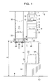
- Figures 1 to 6 show an embodiment.
- An overhead travelling carriage 8 comprises a running driving section 10 that runs through the running rail 4 and a non-contact electricity feeding section 12 that receives electricity fed through the electricity feeding rail 6 by means of, for example, non-contact electricity feeding.
- the electricity feeding rail 6 is provided with, for example, a communication line used between the overhead travelling carriage 8 and a controller (not shown in the drawings) and a dog for controlling stopping at a load port.
- the non-contact electricity feeding section 12 is provided not only with a coil for non-contact electricity feeding but also with a transmission and reception section that transmits and receives signals to and from the controller through the communication line and a sensor that detects the dog.
- the 14 is a lateral feeding section that moves an elevation driving section 16 and a platform 18 to a side of the running rail 4.
- the elevation driving section 16 and the platform 18 are not moved to both sides of the running rail 4 but only to the side opposite to a processing device 50 (to the left of Figure 1).
- the lateral feeding section 14 moves the elevation driving section 16 and the platform 14 to and from one side of the running rail 4.
- paired linear guides 34 guide the elevation driving section 16 to the lateral feeding section 14 of the overhead travelling carriage 8.
- a lateral drive 35 moves the elevation driving section 16 to and from a side of the running rail 4.
- Fall preventing members 20 are provided, for example, in front of and behind the overhead travelling carriage 8 to prevent a cassette 22, an example of an article to be conveyed, from falling from the platform 18 owing to vibration during running.
- the cassette 22 accommodates a semiconductor substrate or the like.
- the platform 18 chucks and supports a flange or the like which projects from a top surface of the cassette 22.
- the overhead buffer 24 is an overhead buffer provided on one side of the running rail 4 opposite the processing device 50.
- a fall preventing fence 26 is provided on the overhead buffer 24 to prevent the cassette 22 from falling.
- the fall preventing fence 26 is shown placed all along the periphery of the overhead buffer 24 so as to have a uniform height. However, the fall preventing fence 26 may be lower on the overhead travelling carriage 8 side and higher on the opposite side.
- the overhead buffer 24 is supported by, for example, paired parallel pipe-like supports 28. End plates 33 or the like are provided at the opposite ends of each of the supports 28.
- the supports 28 are hung from, for example, the ceiling 5 using hanging bolts 30.
- 31 is positioning pins provided on the overhead buffer 24. The positioning pins 31 are fitted into concave portions in a bottom surface of the cassette 22 to position it.
- Fall preventing means are composed of the fall preventing fence 26 and the positioning pins 31.
- the fall preventing fence 26 projects upward from the overhead buffer 24 to a position higher than the positioning pins 31. Accordingly, the height of a part of the fall preventing fence 26 which is closer to the overhead travelling carriage 8 is equal to that of a top portion of the fall preventing means. Without the fall preventing fence 26, the height of the positioning pins 31 is equal to that of the top portion of the fall preventing means.
- An opening 32 is formed in the overhead buffer 24 so as not to block the flow of clean air blown downward from the ceiling 5 toward a floor surface 9. More preferably, the overhead buffer 24 is composed of transparent plastics so as to allow an operator to visually check the overhead buffer 24 for the presence of the cassette 22 easily.
- 50 is a processing device for semiconductors or the like which may be an inspection device or the like.
- 52 is a load port on which a conveyor or the like is provided.
- 54 is an access port through which the cassettes 22 is loaded into and unloaded out of the processing device 50.
- the end plates 33 are hung from the ceiling 5 in a supportive manner using the hanging bolts 30.
- the end plates 33 may be supported by a pillar 48 shown by a chain line and supported by the processing device 50.
- the height H1 of a bottom surface of the cassette 22 on the running overhead travelling carriage 8 is, for example, about 2,500 to 3,000 mm.
- the height H2 of the load port 52 is, for example, about 800 to 1,000 mm. Accordingly, the operator can load and unload the cassette 22 on and from the load port 52.
- the height H3 of the overhead buffer 24 is preferably such that the overhead buffer 24 does not interfere with the operator.
- the height H3 is, for example, at least 2,000 mm.
- the difference D in height between the top of a surface of the fall preventing fence 26 which is closer to the overhead travelling carriage 8 and the bottom surface of the cassette 22 on the running overhead travelling carriage 8 is, for example, about 30 to 300 mm, and in this case, 100 mm.
- the overhead buffer 24 is provided opposite the load port 52 in a plan view.
- the load port 52 is located immediately below the running rail 4.
- the overhead buffer 24 is located opposite the processing device 50 with respect to the running rail 4 and above the load port 52.
- the load port 52 is provided immediately below the running rail 4 at almost the same position as that of the overhead buffer 24 in a plan view along the running direction of the overhead travelling carriage 8.
- the overhead buffer 24 is preferably provided on one of the right and left sides of the running rail 4.
- the difference in position (the difference in position along the running direction of the overhead travelling carriage; also called a shift) between the load port 52 and the overhead buffer 24 is, for example, at most 300 mm.
- a dog (a mark for controlling the overhead travelling carriage) is provided on the feeding rail, provided under the running rail 4.
- a dog 45 indicates the presence of a load port provided upstream of the load port 52 in the running direction.
- a dog 46 is used to control stopping. Only one of the two dogs 45, 46 may be provided.
- the position of the overhead buffer 24 is the same as that of the load port 52.
- the overhead buffer 24 may be shifted, for example, forward from the load port 52 in the running direction of the overhead travelling carriage 8 by about 50 to 300 mm along the running direction.
- the overhead travelling carriage 8 may be stopped at a position obtained by shifting the stopped position of the load port 52 forward by a predetermined distance, the stopped position being determined on the basis of the dogs 45, 46.
- the upstream dog 45 may be used to control stopping.
- FIG. 3 shows that the cassette 22 is being loaded on the overhead buffer 24.
- the platform 18 is hung from the elevation driving section 16 in a supportive manner using a hanging material 36 such as a belt, a rope or a zone plate.
- the hanging material 36 is fed or taken up to elevate or lower the platform 18.
- 37 is an endless belt such as a timing belt.
- An upper side of the loop of the belt 37 is fixed to the lateral feeding section 14 using a fixing section 38.
- a lower side of the loop of the belt 37 is fixed to the elevation driving section 16 using a fixing section 39.
- 40, 41 are paired sprockets (gears).
- 42 is a ball screw
- 43 is a ball screw driving mechanism.
- 44 is a frame.
- the fixing section 39 is moved in the lateral direction by a stroke double that of the frame 44.
- a linear guide or the like guides the lateral movement of the elevation driving section 16.
- An arbitrary mechanism can be used to feed the elevation driving section 16 in the lateral direction.
- Figures 4 to 6 show the control of stopping of the overhead travelling carriage 8 and the loading of the article on the overhead buffer 24 or load port 52. If the overhead travelling carriage 8 stops at the load port 52, stopping control may be performed in accordance with a dog detection signal.
- the overhead buffer 24 is located at the same position as that of the load port 52 along the running direction of the overhead travelling carriage 8. Accordingly, by performing the same control as that performed to stop the load port 52, it is possible to stop the overhead at the correct position. If the overhead buffer 24 is shifted from the load port 52, the stopped position may be changed in accordance with the shift.
- the lateral drive of the lateral feeding section 14 is used to move the elevation driving section 16 forward to the overhead buffer 24. Then, the platform 18 is lowered. While the lateral drive is being moved forward or backward, the bottom surface of the article lies slightly above the fall preventing fence 26 or positioning pins 31 of the overhead buffer 24. Consequently, the lateral drive does not cause any interference.
- the cassette 22 may be guided using the positioning pins 31. Then, the positioning pins 31 and the fall preventing fence 26 are used to prevent the cassette 22 loaded on the overhead buffer 24 from falling even with a strong force acting. during an earthquake.
- the platform 18 may be elevated and the lateral drive is moved backward. Only a small stroke is required to lower and elevate the platform 18 during the above process. Further, only a short time is required for the loading.
- FIG. 6 shows a transfer from the overhead buffer 24 to the load port 52.
- the overhead buffer 24 is located at the same position as that of the load port 52 along the running direction of the overhead travelling carriage 8. Consequently, the overhead travelling carriage 8 need not run during a transfer.
- the lateral drive is moved forward to the overhead buffer 24.
- the platform 18 is lowered and the cassette 22 is transferred from the overhead buffer 24 to the platform 18. This step is called step (c).
- the platform 18 is elevated, and the lateral drive is moved backward.
- the overhead travelling carriage 8 is run by a distance corresponding to the shift. Since the load port 52 is located immediately below the overhead travelling carriage 8, the platform 18 is lowered, and the cassette 22 is loaded on the load port 52. This step is called step (c'). Then, the platform 18 is elevated to complete the transfer.
- the order of the latter three steps in Figure 6 and the former five steps in Figure 5 may be reversed.
- the cassette 22 is transferred from the load port 52 to the platform 18.
- the cassette 22 is transferred from the platform 18 to the overhead buffer 24 instead of from the overhead buffer 24 to the platform 18.
- the embodiment produces the effects below.
- Figure 7 shows an overhead travelling carriage system 72 according to a variation.
- the same reference numerals as those in Figures 1 to 6 represent the same components.
- the overhead buffer 24 for one or more cassettes 22 is provided between processing devices 50, 50'.
- the overhead buffer 24 is hung from, for example, the processing devices 50, 50' in a supportive manner using a pipe 78 or the like.
- the position at which the overhead travelling carriage 8 stops varies between the overhead buffer 24 and the load port 52. Accordingly, dogs 45', 46' are provided to control stopping at the overhead buffer 24.
- the height of the overhead buffer 24 is similar to that in Figure 1.
- the top portion of the fall preventing fence 26 is located slightly below the bottom surface of the cassette 22 conveyed on the overhead travelling carriage 8.
- the overhead travelling carriage 8 can freely deliver and receive the cassette 22 to and from overhead buffers 24 arranged on the right and left sides of the running rail 4.
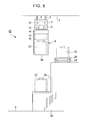
- An overhead travelling carriage system 82 shown in Figure 8 is an example in which the overhead buffer 24 is installed on the top surface of the processing device 50. If the processing device 50 is replaced with a taller one, the overhead buffer 24 is removed. In this example, the height of the overhead buffer 24 is also such that the top portion of the fall preventing fence 26 is located slightly above the bottom surface of the cassette 22 conveyed on the overhead travelling carriage 8. In the other respects, this example is similar to the embodiment shown in Figures 1 to 6.
Landscapes
- Engineering & Computer Science (AREA)
- Mechanical Engineering (AREA)
- Warehouses Or Storage Devices (AREA)
- Container, Conveyance, Adherence, Positioning, Of Wafer (AREA)
- Carriers, Traveling Bodies, And Overhead Traveling Cranes (AREA)
Applications Claiming Priority (4)
| Application Number | Priority Date | Filing Date | Title |
|---|---|---|---|
| JP2003432431 | 2003-12-26 | ||
| JP2003432431 | 2003-12-26 | ||
| JP2004186312 | 2004-06-24 | ||
| JP2004186312A JP4045451B2 (ja) | 2003-12-26 | 2004-06-24 | 天井走行車システム |
Publications (2)
| Publication Number | Publication Date |
|---|---|
| EP1547943A1 true EP1547943A1 (de) | 2005-06-29 |
| EP1547943B1 EP1547943B1 (de) | 2009-09-30 |
Family
ID=34554879
Family Applications (1)
| Application Number | Title | Priority Date | Filing Date |
|---|---|---|---|
| EP04028271A Expired - Lifetime EP1547943B1 (de) | 2003-12-26 | 2004-11-29 | Schienenlaufwagensystem |
Country Status (6)
| Country | Link |
|---|---|
| US (1) | US7441999B2 (de) |
| EP (1) | EP1547943B1 (de) |
| JP (1) | JP4045451B2 (de) |
| KR (1) | KR100810530B1 (de) |
| DE (1) | DE602004023366D1 (de) |
| TW (1) | TW200521051A (de) |
Cited By (6)
| Publication number | Priority date | Publication date | Assignee | Title |
|---|---|---|---|---|
| EP1868236A1 (de) * | 2006-06-16 | 2007-12-19 | Murata Kikai Kabushiki Kaisha | Hängefahrzeugsystem und Transportverfahren damit |
| US7637380B2 (en) * | 2007-07-23 | 2009-12-29 | Muratec Automation Co., Ltd. | Transporting apparatus, transporting system, and elongation mechanism |
| CN101837871A (zh) * | 2009-03-17 | 2010-09-22 | 村田机械株式会社 | 桥式输送系统及物品的移载方法 |
| US8231324B2 (en) | 2007-03-07 | 2012-07-31 | Daifuku Co., Ltd. | Article storage facility |
| DE102007002158B4 (de) * | 2006-01-17 | 2012-10-25 | Murata Kikai K.K. | Über Kopf fahrendes Fahrzeugsystem und Artikellagerungsverfahren in dem über Kopf fahrenden Fahrzeugsystem |
| WO2020160585A3 (de) * | 2019-02-07 | 2020-12-24 | Tgw Mechanics Gmbh | Transportträgersystem und hängefördervorrichtung mit transportträgern zum transport von hängewaren |
Families Citing this family (43)
| Publication number | Priority date | Publication date | Assignee | Title |
|---|---|---|---|---|
| KR100882376B1 (ko) | 2002-06-19 | 2009-02-05 | 브룩스 오토메이션, 인크. | 수직형 회전저장선반 및 오버헤드 호이스트의 조합에 기초한 반도체 제조용 자동식 재료 처리 시스템 |
| KR100880291B1 (ko) | 2002-10-11 | 2009-01-23 | 브룩스 오토메이션, 인크. | 자동 재료 핸들링 시스템 |
| DE102004032659B4 (de) * | 2004-07-01 | 2008-10-30 | Atotech Deutschland Gmbh | Vorrichtung und Verfahren zum chemischen oder elektrolytischen Behandeln von Behandlungsgut sowie die Verwendung der Vorrichtung |
| JP4394027B2 (ja) | 2005-04-05 | 2010-01-06 | 村田機械株式会社 | 天井走行車システム |
| JP4264834B2 (ja) * | 2005-07-04 | 2009-05-20 | 村田機械株式会社 | 有軌道台車システム |
| JP4632091B2 (ja) * | 2005-08-30 | 2011-02-16 | 株式会社ダイフク | 物品搬送設備 |
| KR20140091768A (ko) * | 2005-11-07 | 2014-07-22 | 브룩스 오토메이션 인코퍼레이티드 | 반도체 작업대상물 공정처리 시스템 |
| US20070160448A1 (en) * | 2006-01-06 | 2007-07-12 | International Business Machines Corporation | Receipt and delivery control system for front opening unified and reticle storage pods |
| JP4887804B2 (ja) * | 2006-01-26 | 2012-02-29 | 村田機械株式会社 | 搬送システム |
| JP4427755B2 (ja) * | 2006-02-03 | 2010-03-10 | 村田機械株式会社 | 搬送システム |
| KR101841753B1 (ko) * | 2006-08-18 | 2018-03-23 | 브룩스 오토메이션 인코퍼레이티드 | 용량이 축소된 캐리어, 이송, 로드 포트, 버퍼 시스템 |
| JP4193186B2 (ja) | 2006-11-02 | 2008-12-10 | 村田機械株式会社 | 天井走行車 |
| JP4277287B2 (ja) | 2006-11-27 | 2009-06-10 | 村田機械株式会社 | 天井走行車 |
| JP4688824B2 (ja) * | 2007-01-12 | 2011-05-25 | 村田機械株式会社 | 天井走行車システム及び天井走行車システムの周囲の処理装置の搬出入方法 |
| JP5088468B2 (ja) | 2007-03-09 | 2012-12-05 | 村田機械株式会社 | 懸垂式搬送台車を用いた搬送システム |
| US20080240892A1 (en) * | 2007-03-28 | 2008-10-02 | International Business Machines Corporation | Storage buffer device for automated material handling systems |
| DE102007035839B4 (de) * | 2007-07-31 | 2017-06-22 | Globalfoundries Dresden Module One Limited Liability Company & Co. Kg | Verfahren und System zum lokalen Aufbewahren von Substratbehältern in einem Deckentransportsystem zum Verbessern der Aufnahme/Abgabe-Kapazitäten von Prozessanlagen |
| JP5163866B2 (ja) * | 2007-12-10 | 2013-03-13 | 村田機械株式会社 | 天井バッファとその移設方法 |
| JP2009196748A (ja) * | 2008-02-20 | 2009-09-03 | Murata Mach Ltd | 載置台 |
| JP5062485B2 (ja) * | 2008-04-09 | 2012-10-31 | 株式会社ダイフク | 物品搬送設備 |
| JP5234328B2 (ja) * | 2008-04-11 | 2013-07-10 | 株式会社ダイフク | 物品収納設備 |
| US9048274B2 (en) * | 2008-12-08 | 2015-06-02 | Taiwan Semiconductor Manufacturing Co., Ltd. | Portable stocker and method of using same |
| JP5187200B2 (ja) * | 2009-01-13 | 2013-04-24 | 村田機械株式会社 | 天井搬送車 |
| JP2010184760A (ja) * | 2009-02-10 | 2010-08-26 | Muratec Automation Co Ltd | 移載システム |
| US8483866B2 (en) * | 2009-04-30 | 2013-07-09 | Taiwan Semiconductor Manufacturing Co., Ltd. | Automated materials handling system having multiple categories of overhead buffers |
| JP5463758B2 (ja) * | 2009-06-26 | 2014-04-09 | 村田機械株式会社 | 保管庫 |
| JP2011029550A (ja) * | 2009-07-29 | 2011-02-10 | Muratec Automation Co Ltd | 搬送システム及びその設定方法 |
| JP5024337B2 (ja) * | 2009-07-29 | 2012-09-12 | 村田機械株式会社 | 搬送システム及び保管装置 |
| TWI440119B (zh) * | 2010-11-08 | 2014-06-01 | 華亞科技股份有限公司 | 具有多層式軌道結構之台車系統及其控制方法 |
| GB201314313D0 (en) | 2013-08-09 | 2013-09-25 | Ocado Ltd | Apparatus for retrieving units from a storage system |
| US11858738B2 (en) | 2013-08-09 | 2024-01-02 | Ocado Innovation Limited | Apparatus for retrieving units from a storage system |
| KR101576543B1 (ko) | 2013-12-20 | 2015-12-10 | 주식회사 에스에프에이 | 이송대차 시스템 및 이송대차를 이용한 대상물 이적재방법 |
| JP6315098B2 (ja) * | 2014-08-26 | 2018-04-25 | 村田機械株式会社 | 仕分けシステムと仕分け方法 |
| US10418263B2 (en) | 2018-01-20 | 2019-09-17 | Boris Kesil | Overhead transportation system for transporting objects between multiple work stations |
| JP7256360B2 (ja) * | 2018-12-14 | 2023-04-12 | シンフォニアテクノロジー株式会社 | 搬送異常検知システム |
| US11912608B2 (en) | 2019-10-01 | 2024-02-27 | Owens-Brockway Glass Container Inc. | Glass manufacturing |
| US12131932B2 (en) | 2020-07-28 | 2024-10-29 | Changxin Memory Technologies, Inc. | Transfer system and transfer method |
| CN113998403B (zh) * | 2020-07-28 | 2022-09-23 | 长鑫存储技术有限公司 | 转运系统及转运方法 |
| US12291410B2 (en) | 2020-10-01 | 2025-05-06 | Owens-Brockway Glass Container Inc. | Bulk material handling methods, systems, subsystems, and apparatuses |
| TWI797040B (zh) * | 2022-02-17 | 2023-03-21 | 盟立自動化股份有限公司 | 高空走行式無人搬運車的搬運系統及無人搬運車 |
| JP7798077B2 (ja) * | 2023-04-20 | 2026-01-14 | 株式会社ダイフク | 天井保管棚、および搬送システム |
| CN119818187B (zh) * | 2023-10-12 | 2025-10-28 | 武汉联影智融医疗科技有限公司 | 滑台机构和手术机器人 |
| CN119263082B (zh) * | 2024-11-08 | 2025-12-09 | 珠海格力电子元器件有限公司 | 一种天车装置及其控制方法 |
Citations (5)
| Publication number | Priority date | Publication date | Assignee | Title |
|---|---|---|---|---|
| US6113341A (en) * | 1997-12-22 | 2000-09-05 | Murata Kikai Kabushiki Kaisha | Tracking cart system |
| US6450318B1 (en) * | 2000-06-16 | 2002-09-17 | Tec Engineering Corporation | Overhead monorail system |
| WO2003088350A1 (fr) * | 2002-04-12 | 2003-10-23 | Hirata Corporation | Systeme de convoyage de contenants fermes |
| US20030235486A1 (en) * | 2002-06-19 | 2003-12-25 | Doherty Brian J. | Automated material handling system for semiconductor manufacturing based on a combination of vertical carousels and overhead hoists |
| US20040109746A1 (en) * | 2002-12-09 | 2004-06-10 | Murata Kikai Kabushiki Kaisha | Overhead travelling carriage system |
Family Cites Families (20)
| Publication number | Priority date | Publication date | Assignee | Title |
|---|---|---|---|---|
| JPH06298305A (ja) * | 1993-04-16 | 1994-10-25 | Murata Mach Ltd | 有軌道台車システム |
| US5570990A (en) * | 1993-11-05 | 1996-11-05 | Asyst Technologies, Inc. | Human guided mobile loader stocker |
| US6599075B2 (en) * | 1994-04-28 | 2003-07-29 | Semitool, Inc. | Semiconductor wafer processing apparatus |
| US6471460B1 (en) * | 1996-07-15 | 2002-10-29 | Semitool, Inc. | Apparatus for processing a microelectronic workpiece including a workpiece cassette inventory assembly |
| JP3436334B2 (ja) * | 1996-08-06 | 2003-08-11 | 株式会社ダイフク | 物品搬送設備 |
| JP3067656B2 (ja) | 1996-09-30 | 2000-07-17 | 村田機械株式会社 | ワーク搬送システム |
| JPH10279279A (ja) * | 1997-04-04 | 1998-10-20 | Ishikawajima Harima Heavy Ind Co Ltd | コンテナターミナルの天井クレーン |
| US6579052B1 (en) * | 1997-07-11 | 2003-06-17 | Asyst Technologies, Inc. | SMIF pod storage, delivery and retrieval system |
| US6079927A (en) * | 1998-04-22 | 2000-06-27 | Varian Semiconductor Equipment Associates, Inc. | Automated wafer buffer for use with wafer processing equipment |
| US6604624B2 (en) * | 1998-09-22 | 2003-08-12 | Hirata Corporation | Work conveying system |
| US6283692B1 (en) * | 1998-12-01 | 2001-09-04 | Applied Materials, Inc. | Apparatus for storing and moving a cassette |
| US6435330B1 (en) * | 1998-12-18 | 2002-08-20 | Asyai Technologies, Inc. | In/out load port transfer mechanism |
| JP4267742B2 (ja) * | 1999-03-12 | 2009-05-27 | 平田機工株式会社 | 天井搬送装置及びこれを用いた物流ラインシステム |
| DE19921072A1 (de) * | 1999-05-08 | 2000-11-09 | Acr Automation In Cleanroom | Einrichtung zum Handhaben von Substraten innerhalb und außerhalb eines Reinstarbeitsraumes |
| JP2001301914A (ja) * | 2000-04-19 | 2001-10-31 | Murata Mach Ltd | ラック |
| AU2001279280A1 (en) * | 2000-07-07 | 2002-01-21 | Hover-Davis, Inc. | Component source interchange gantry |
| US6726429B2 (en) * | 2002-02-19 | 2004-04-27 | Vertical Solutions, Inc. | Local store for a wafer processing station |
| FR2844258B1 (fr) * | 2002-09-06 | 2005-06-03 | Recif Sa | Systeme de transport et stockage de conteneurs de plaques de semi-conducteur, et mecanisme de transfert |
| KR100880291B1 (ko) * | 2002-10-11 | 2009-01-23 | 브룩스 오토메이션, 인크. | 자동 재료 핸들링 시스템 |
| US20050008467A1 (en) * | 2003-07-11 | 2005-01-13 | Rich Huang | Load port transfer device |
-
2004
- 2004-06-24 JP JP2004186312A patent/JP4045451B2/ja not_active Expired - Lifetime
- 2004-08-17 TW TW093124689A patent/TW200521051A/zh not_active IP Right Cessation
- 2004-10-27 KR KR1020040086186A patent/KR100810530B1/ko not_active Expired - Lifetime
- 2004-11-29 DE DE602004023366T patent/DE602004023366D1/de not_active Expired - Lifetime
- 2004-11-29 EP EP04028271A patent/EP1547943B1/de not_active Expired - Lifetime
- 2004-12-07 US US11/004,886 patent/US7441999B2/en not_active Expired - Lifetime
Patent Citations (5)
| Publication number | Priority date | Publication date | Assignee | Title |
|---|---|---|---|---|
| US6113341A (en) * | 1997-12-22 | 2000-09-05 | Murata Kikai Kabushiki Kaisha | Tracking cart system |
| US6450318B1 (en) * | 2000-06-16 | 2002-09-17 | Tec Engineering Corporation | Overhead monorail system |
| WO2003088350A1 (fr) * | 2002-04-12 | 2003-10-23 | Hirata Corporation | Systeme de convoyage de contenants fermes |
| US20030235486A1 (en) * | 2002-06-19 | 2003-12-25 | Doherty Brian J. | Automated material handling system for semiconductor manufacturing based on a combination of vertical carousels and overhead hoists |
| US20040109746A1 (en) * | 2002-12-09 | 2004-06-10 | Murata Kikai Kabushiki Kaisha | Overhead travelling carriage system |
Cited By (10)
| Publication number | Priority date | Publication date | Assignee | Title |
|---|---|---|---|---|
| DE102007002158B4 (de) * | 2006-01-17 | 2012-10-25 | Murata Kikai K.K. | Über Kopf fahrendes Fahrzeugsystem und Artikellagerungsverfahren in dem über Kopf fahrenden Fahrzeugsystem |
| EP1868236A1 (de) * | 2006-06-16 | 2007-12-19 | Murata Kikai Kabushiki Kaisha | Hängefahrzeugsystem und Transportverfahren damit |
| CN101088905B (zh) * | 2006-06-16 | 2010-06-23 | 村田机械株式会社 | 桥式吊车系统 |
| US8231324B2 (en) | 2007-03-07 | 2012-07-31 | Daifuku Co., Ltd. | Article storage facility |
| US7637380B2 (en) * | 2007-07-23 | 2009-12-29 | Muratec Automation Co., Ltd. | Transporting apparatus, transporting system, and elongation mechanism |
| CN101353109B (zh) * | 2007-07-23 | 2012-07-04 | 村田自动化机械有限公司 | 运输设备、运输系统以及伸长机构 |
| CN101837871A (zh) * | 2009-03-17 | 2010-09-22 | 村田机械株式会社 | 桥式输送系统及物品的移载方法 |
| CN101837871B (zh) * | 2009-03-17 | 2014-08-20 | 村田机械株式会社 | 桥式输送系统及物品的移载方法 |
| WO2020160585A3 (de) * | 2019-02-07 | 2020-12-24 | Tgw Mechanics Gmbh | Transportträgersystem und hängefördervorrichtung mit transportträgern zum transport von hängewaren |
| US12479666B2 (en) | 2019-02-07 | 2025-11-25 | Tgw Logistics Gmbh | Transport carrier system and overhead conveyor device comprising transport carriers for transporting suspended goods |
Also Published As
| Publication number | Publication date |
|---|---|
| EP1547943B1 (de) | 2009-09-30 |
| US20050139564A1 (en) | 2005-06-30 |
| US7441999B2 (en) | 2008-10-28 |
| KR100810530B1 (ko) | 2008-03-10 |
| JP4045451B2 (ja) | 2008-02-13 |
| DE602004023366D1 (de) | 2009-11-12 |
| KR20050066985A (ko) | 2005-06-30 |
| TW200521051A (en) | 2005-07-01 |
| TWI324129B (de) | 2010-05-01 |
| JP2005206371A (ja) | 2005-08-04 |
Similar Documents
| Publication | Publication Date | Title |
|---|---|---|
| US7441999B2 (en) | Overhead travelling carriage system | |
| US7887278B2 (en) | Overhead travelling carriage system | |
| US7891929B2 (en) | Carriage system | |
| US7753639B2 (en) | Overhead travelling carriage system | |
| KR100679938B1 (ko) | 천정 주행차 시스템 | |
| KR101463473B1 (ko) | 이송 장치 | |
| US8814490B2 (en) | Article storage facility | |
| KR101942394B1 (ko) | 퍼지 장치 및 퍼지 방법 | |
| TWI641549B (zh) | Carrier handling system and handling method | |
| CN1333730A (zh) | 一体式的隔舱内部输送、存放及运送装置 | |
| KR20120055493A (ko) | 기판 컨테이너 보관 시스템 | |
| KR20140033496A (ko) | 반송 시스템 | |
| KR102700084B1 (ko) | 그리퍼 장치, 반송차, 및 반송 방법 | |
| JP2008120586A (ja) | 物品収納装置 | |
| KR20210139147A (ko) | 물품 반송 장치 | |
| JP4126559B2 (ja) | 天井走行車システム | |
| CN113557487A (zh) | 输送车系统 | |
| CN1277138A (zh) | 用于生产半导体产品的设备 | |
| JP2008120585A (ja) | 物品収納装置用フレーム構造 | |
| CN121127749A (zh) | 模块化机架提升装置和机架提升系统 | |
| CN117566352A (zh) | 料盘移载系统 |
Legal Events
| Date | Code | Title | Description |
|---|---|---|---|
| PUAI | Public reference made under article 153(3) epc to a published international application that has entered the european phase |
Free format text: ORIGINAL CODE: 0009012 |
|
| AK | Designated contracting states |
Kind code of ref document: A1 Designated state(s): AT BE BG CH CY CZ DE DK EE ES FI FR GB GR HU IE IS IT LI LU MC NL PL PT RO SE SI SK TR |
|
| AX | Request for extension of the european patent |
Extension state: AL HR LT LV MK YU |
|
| 17P | Request for examination filed |
Effective date: 20050725 |
|
| AKX | Designation fees paid |
Designated state(s): DE FR GB IT |
|
| 17Q | First examination report despatched |
Effective date: 20060420 |
|
| GRAP | Despatch of communication of intention to grant a patent |
Free format text: ORIGINAL CODE: EPIDOSNIGR1 |
|
| GRAS | Grant fee paid |
Free format text: ORIGINAL CODE: EPIDOSNIGR3 |
|
| GRAA | (expected) grant |
Free format text: ORIGINAL CODE: 0009210 |
|
| AK | Designated contracting states |
Kind code of ref document: B1 Designated state(s): DE FR GB IT |
|
| REG | Reference to a national code |
Ref country code: GB Ref legal event code: FG4D |
|
| REF | Corresponds to: |
Ref document number: 602004023366 Country of ref document: DE Date of ref document: 20091112 Kind code of ref document: P |
|
| PLBE | No opposition filed within time limit |
Free format text: ORIGINAL CODE: 0009261 |
|
| STAA | Information on the status of an ep patent application or granted ep patent |
Free format text: STATUS: NO OPPOSITION FILED WITHIN TIME LIMIT |
|
| GBPC | Gb: european patent ceased through non-payment of renewal fee |
Effective date: 20091230 |
|
| 26N | No opposition filed |
Effective date: 20100701 |
|
| PG25 | Lapsed in a contracting state [announced via postgrant information from national office to epo] |
Ref country code: GB Free format text: LAPSE BECAUSE OF NON-PAYMENT OF DUE FEES Effective date: 20091230 |
|
| PGFP | Annual fee paid to national office [announced via postgrant information from national office to epo] |
Ref country code: IT Payment date: 20101125 Year of fee payment: 7 |
|
| PG25 | Lapsed in a contracting state [announced via postgrant information from national office to epo] |
Ref country code: IT Free format text: LAPSE BECAUSE OF NON-PAYMENT OF DUE FEES Effective date: 20121129 |
|
| REG | Reference to a national code |
Ref country code: FR Ref legal event code: PLFP Year of fee payment: 12 |
|
| PGFP | Annual fee paid to national office [announced via postgrant information from national office to epo] |
Ref country code: FR Payment date: 20151119 Year of fee payment: 12 |
|
| REG | Reference to a national code |
Ref country code: FR Ref legal event code: ST Effective date: 20170731 |
|
| PG25 | Lapsed in a contracting state [announced via postgrant information from national office to epo] |
Ref country code: FR Free format text: LAPSE BECAUSE OF NON-PAYMENT OF DUE FEES Effective date: 20161130 |
|
| PGFP | Annual fee paid to national office [announced via postgrant information from national office to epo] |
Ref country code: DE Payment date: 20231019 Year of fee payment: 20 |
|
| REG | Reference to a national code |
Ref country code: DE Ref legal event code: R071 Ref document number: 602004023366 Country of ref document: DE |