EP1547854A1 - Dispositif et procede de commande d'un moteur premier - Google Patents
Dispositif et procede de commande d'un moteur premier Download PDFInfo
- Publication number
- EP1547854A1 EP1547854A1 EP03741239A EP03741239A EP1547854A1 EP 1547854 A1 EP1547854 A1 EP 1547854A1 EP 03741239 A EP03741239 A EP 03741239A EP 03741239 A EP03741239 A EP 03741239A EP 1547854 A1 EP1547854 A1 EP 1547854A1
- Authority
- EP
- European Patent Office
- Prior art keywords
- torque
- motor
- skid
- angular acceleration
- torque restriction
- Prior art date
- Legal status (The legal status is an assumption and is not a legal conclusion. Google has not performed a legal analysis and makes no representation as to the accuracy of the status listed.)
- Granted
Links
Images


Classifications
-
- B—PERFORMING OPERATIONS; TRANSPORTING
- B60—VEHICLES IN GENERAL
- B60L—PROPULSION OF ELECTRICALLY-PROPELLED VEHICLES; SUPPLYING ELECTRIC POWER FOR AUXILIARY EQUIPMENT OF ELECTRICALLY-PROPELLED VEHICLES; ELECTRODYNAMIC BRAKE SYSTEMS FOR VEHICLES IN GENERAL; MAGNETIC SUSPENSION OR LEVITATION FOR VEHICLES; MONITORING OPERATING VARIABLES OF ELECTRICALLY-PROPELLED VEHICLES; ELECTRIC SAFETY DEVICES FOR ELECTRICALLY-PROPELLED VEHICLES
- B60L15/00—Methods, circuits, or devices for controlling the traction-motor speed of electrically-propelled vehicles
- B60L15/20—Methods, circuits, or devices for controlling the traction-motor speed of electrically-propelled vehicles for control of the vehicle or its driving motor to achieve a desired performance, e.g. speed, torque, programmed variation of speed
-
- B—PERFORMING OPERATIONS; TRANSPORTING
- B60—VEHICLES IN GENERAL
- B60L—PROPULSION OF ELECTRICALLY-PROPELLED VEHICLES; SUPPLYING ELECTRIC POWER FOR AUXILIARY EQUIPMENT OF ELECTRICALLY-PROPELLED VEHICLES; ELECTRODYNAMIC BRAKE SYSTEMS FOR VEHICLES IN GENERAL; MAGNETIC SUSPENSION OR LEVITATION FOR VEHICLES; MONITORING OPERATING VARIABLES OF ELECTRICALLY-PROPELLED VEHICLES; ELECTRIC SAFETY DEVICES FOR ELECTRICALLY-PROPELLED VEHICLES
- B60L3/00—Electric devices on electrically-propelled vehicles for safety purposes; Monitoring operating variables, e.g. speed, deceleration or energy consumption
- B60L3/10—Indicating wheel slip ; Correction of wheel slip
- B60L3/106—Indicating wheel slip ; Correction of wheel slip for maintaining or recovering the adhesion of the drive wheels
-
- B—PERFORMING OPERATIONS; TRANSPORTING
- B60—VEHICLES IN GENERAL
- B60L—PROPULSION OF ELECTRICALLY-PROPELLED VEHICLES; SUPPLYING ELECTRIC POWER FOR AUXILIARY EQUIPMENT OF ELECTRICALLY-PROPELLED VEHICLES; ELECTRODYNAMIC BRAKE SYSTEMS FOR VEHICLES IN GENERAL; MAGNETIC SUSPENSION OR LEVITATION FOR VEHICLES; MONITORING OPERATING VARIABLES OF ELECTRICALLY-PROPELLED VEHICLES; ELECTRIC SAFETY DEVICES FOR ELECTRICALLY-PROPELLED VEHICLES
- B60L15/00—Methods, circuits, or devices for controlling the traction-motor speed of electrically-propelled vehicles
- B60L15/20—Methods, circuits, or devices for controlling the traction-motor speed of electrically-propelled vehicles for control of the vehicle or its driving motor to achieve a desired performance, e.g. speed, torque, programmed variation of speed
- B60L15/2045—Methods, circuits, or devices for controlling the traction-motor speed of electrically-propelled vehicles for control of the vehicle or its driving motor to achieve a desired performance, e.g. speed, torque, programmed variation of speed for optimising the use of energy
-
- B—PERFORMING OPERATIONS; TRANSPORTING
- B60—VEHICLES IN GENERAL
- B60L—PROPULSION OF ELECTRICALLY-PROPELLED VEHICLES; SUPPLYING ELECTRIC POWER FOR AUXILIARY EQUIPMENT OF ELECTRICALLY-PROPELLED VEHICLES; ELECTRODYNAMIC BRAKE SYSTEMS FOR VEHICLES IN GENERAL; MAGNETIC SUSPENSION OR LEVITATION FOR VEHICLES; MONITORING OPERATING VARIABLES OF ELECTRICALLY-PROPELLED VEHICLES; ELECTRIC SAFETY DEVICES FOR ELECTRICALLY-PROPELLED VEHICLES
- B60L3/00—Electric devices on electrically-propelled vehicles for safety purposes; Monitoring operating variables, e.g. speed, deceleration or energy consumption
- B60L3/10—Indicating wheel slip ; Correction of wheel slip
- B60L3/102—Indicating wheel slip ; Correction of wheel slip of individual wheels
-
- F—MECHANICAL ENGINEERING; LIGHTING; HEATING; WEAPONS; BLASTING
- F02—COMBUSTION ENGINES; HOT-GAS OR COMBUSTION-PRODUCT ENGINE PLANTS
- F02D—CONTROLLING COMBUSTION ENGINES
- F02D29/00—Controlling engines, such controlling being peculiar to the devices driven thereby, the devices being other than parts or accessories essential to engine operation, e.g. controlling of engines by signals external thereto
- F02D29/02—Controlling engines, such controlling being peculiar to the devices driven thereby, the devices being other than parts or accessories essential to engine operation, e.g. controlling of engines by signals external thereto peculiar to engines driving vehicles; peculiar to engines driving variable pitch propellers
-
- B—PERFORMING OPERATIONS; TRANSPORTING
- B60—VEHICLES IN GENERAL
- B60L—PROPULSION OF ELECTRICALLY-PROPELLED VEHICLES; SUPPLYING ELECTRIC POWER FOR AUXILIARY EQUIPMENT OF ELECTRICALLY-PROPELLED VEHICLES; ELECTRODYNAMIC BRAKE SYSTEMS FOR VEHICLES IN GENERAL; MAGNETIC SUSPENSION OR LEVITATION FOR VEHICLES; MONITORING OPERATING VARIABLES OF ELECTRICALLY-PROPELLED VEHICLES; ELECTRIC SAFETY DEVICES FOR ELECTRICALLY-PROPELLED VEHICLES
- B60L2200/00—Type of vehicles
- B60L2200/26—Rail vehicles
-
- B—PERFORMING OPERATIONS; TRANSPORTING
- B60—VEHICLES IN GENERAL
- B60L—PROPULSION OF ELECTRICALLY-PROPELLED VEHICLES; SUPPLYING ELECTRIC POWER FOR AUXILIARY EQUIPMENT OF ELECTRICALLY-PROPELLED VEHICLES; ELECTRODYNAMIC BRAKE SYSTEMS FOR VEHICLES IN GENERAL; MAGNETIC SUSPENSION OR LEVITATION FOR VEHICLES; MONITORING OPERATING VARIABLES OF ELECTRICALLY-PROPELLED VEHICLES; ELECTRIC SAFETY DEVICES FOR ELECTRICALLY-PROPELLED VEHICLES
- B60L2270/00—Problem solutions or means not otherwise provided for
- B60L2270/10—Emission reduction
- B60L2270/14—Emission reduction of noise
- B60L2270/145—Structure borne vibrations
-
- Y—GENERAL TAGGING OF NEW TECHNOLOGICAL DEVELOPMENTS; GENERAL TAGGING OF CROSS-SECTIONAL TECHNOLOGIES SPANNING OVER SEVERAL SECTIONS OF THE IPC; TECHNICAL SUBJECTS COVERED BY FORMER USPC CROSS-REFERENCE ART COLLECTIONS [XRACs] AND DIGESTS
- Y02—TECHNOLOGIES OR APPLICATIONS FOR MITIGATION OR ADAPTATION AGAINST CLIMATE CHANGE
- Y02T—CLIMATE CHANGE MITIGATION TECHNOLOGIES RELATED TO TRANSPORTATION
- Y02T10/00—Road transport of goods or passengers
- Y02T10/60—Other road transportation technologies with climate change mitigation effect
- Y02T10/64—Electric machine technologies in electromobility
-
- Y—GENERAL TAGGING OF NEW TECHNOLOGICAL DEVELOPMENTS; GENERAL TAGGING OF CROSS-SECTIONAL TECHNOLOGIES SPANNING OVER SEVERAL SECTIONS OF THE IPC; TECHNICAL SUBJECTS COVERED BY FORMER USPC CROSS-REFERENCE ART COLLECTIONS [XRACs] AND DIGESTS
- Y02—TECHNOLOGIES OR APPLICATIONS FOR MITIGATION OR ADAPTATION AGAINST CLIMATE CHANGE
- Y02T—CLIMATE CHANGE MITIGATION TECHNOLOGIES RELATED TO TRANSPORTATION
- Y02T10/00—Road transport of goods or passengers
- Y02T10/60—Other road transportation technologies with climate change mitigation effect
- Y02T10/72—Electric energy management in electromobility
Definitions
- the present invention relates to a motor control apparatus and a motor control method. More specifically the invention pertains to a motor control apparatus that controls a motor, which is mounted on a vehicle and outputs power to a drive shaft linked to drive wheels, as well as to a corresponding motor control method.
- One proposed motor control apparatus of controlling a motor mounted on a vehicle restricts an output torque level from the motor to a drive shaft, in response to detection of wheelspin of drive wheels caused by the torque output from the motor (see, for example, Japanese Patent Laid-Open Gazette No. 2001-295676).
- This known motor control apparatus detects the occurrence of a skid in response to an increase in angular acceleration of the drive wheels (that is, a time variation of angular velocity) over a predetermined threshold value and lowers the output torque level from the motor.
- the restricted output torque level from the motor is restored, in response to detection of convergence of the skid.
- the motor control apparatus and the corresponding motor control method of the invention aim to prevent potential vibrations of a driving system in the course of skid control.
- a first motor control apparatus of the invention controls a motor, which is mounted on a vehicle and outputs power to a drive shaft linked to drive wheels, and includes: an angular acceleration measurement module that measures an angular acceleration of either the drive shaft or a rotating shaft of the motor; a skid detection module that detects occurrence of a skid due to wheelspin of the drive wheels, in response to an increase in measured angular acceleration over a preset value; a first torque restriction control module that, in response to detection of the occurrence of a skid by the skid detection module, sets a certain torque restriction rate to restrict an output torque level for reduction of the skid and controls the motor with the restricted output torque level; and a torque restoration control module that restores the output torque level restricted by the first torque restriction control module and controls the motor with the restored output torque level at a predetermined timing when the angular acceleration measured by the angular acceleration measurement module has an increase in the course of convergence of the skid.
- the first motor control apparatus of the invention restricts the output torque level to the drive shaft for reduction of the detected skid.
- the restricted output torque level is restored at the predetermined timing when the angular acceleration has an increase in the course of convergence of the skid by the restriction of the output torque level.
- the restricted output torque level is restored at the timing when the direction of the torque applied on the drive shaft in the course of restoration from the torque restriction is completely identical with the direction of the angular acceleration applied on the drive shaft.
- the predetermined timing may represent a change timing of the measured angular acceleration from negative to positive. This arrangement more effectively prevents the potential torsional vibrations of the drive shaft.
- the torque restoration control module may control the motor with a lower torque restriction rate than the certain torque restriction rate set by the first torque restriction control module for a preset time period, so as to restore the restricted output torque level. This arrangement more effectively prevents the potential torsional vibrations of the drive shaft.
- the first motor control apparatus of the invention may further include: a second torque restriction control module that controls the motor with setting of a specified torque restriction, when an absolute value of a first negative peak of the measured angular acceleration detected after the increase over the preset value is greater than a predetermined threshold value.
- the negative peak of the angular acceleration is expected to reflect a change of the road surface condition.
- the specified torque restriction corresponding to the change of the road surface condition for the predetermined time period desirably prevents the potential torsional vibrations of the drive shaft caused by the changing road surface condition.
- the second torque restriction control module may control the motor with a torque restriction rate set corresponding to the absolute value of the first negative peak as the specified torque restriction. Further, in the first motor control apparatus of the invention, the second torque restriction control module may control the motor with the setting of the specified torque restriction for a predetermined time period.
- the first torque restriction control module may control the motor to have a torque variation in a preset allowable range. This arrangement desirably reduces a potential torque shock due to restriction of the output torque level to the drive shaft in response to detection of the occurrence of a skid.
- a second motor control apparatus of the invention controls a motor, which is mounted on a vehicle and outputs power to a drive shaft linked to drive wheels, and includes: a skid detection module that detects occurrence of a skid due to wheelspin of the drive wheels; a torque restriction rate setting module that, in response to detection of the occurrence of a skid by the skid detection module, sets a torque restriction rate of torque output to the drive shaft corresponding to a degree of the detected skid; a torque restriction rate correction module that, when control of the motor with the set torque restriction rate makes a torque variation out of a preset allowable range, corrects the torque restriction rate to limit the torque variation in the preset allowable range; and a torque restriction control module that controls the motor, based on a power demand to the drive shaft and the set or corrected torque restriction rate.
- the second motor control apparatus of the invention sets the torque restriction rate of torque output to the drive shaft corresponding to the degree of the detected skid.
- the torque restriction rate is corrected to limit the torque variation in the preset allowable range.
- the motor is controlled, based on the power demand to the drive shaft and the set or corrected torque restriction rate.
- the torque restriction rate set corresponding to the degree of the detected skid is regulated to limit the torque variation of the motor in the preset allowable range. This arrangement thus effectively reduces a potential torque shock caused by restriction of the torque output to the drive shaft (a decrease in torque level) in response to the occurrence of a skid.
- the second motor control apparatus of the invention may further include: an angular acceleration measurement module that measures an angular acceleration of either the drive shaft or a rotating shaft of the motor.
- the skid detection module may detect the occurrence of a skid when the measured angular acceleration exceeds a predetermined threshold value, and in response to detection of the occurrence of a skid by the skid detection module, the torque restriction rate setting module may set the torque restriction rate of torque output to the drive shaft corresponding to the angular acceleration measured by the angular acceleration measurement module. Further, in the second motor control apparatus of the invention, the torque restriction rate setting module may increase the torque restriction rate with an increase in angular acceleration.
- a first motor control method of the invention controls a motor, which is mounted on a vehicle and outputs power to a drive shaft linked to drive wheels, and includes the steps of: (a) measuring an angular acceleration of either the drive shaft or a rotating shaft of the motor; (b) detecting occurrence of a skid due to wheelspin of the drive wheels, in response to an increase in measured angular acceleration over a preset value; (c) in response to detection of the occurrence of a skid, setting a certain torque restriction rate to restrict an output torque level for reduction of the skid and controlling the motor with the restricted output torque level; and (d) restoring the output torque level restricted in the step (c) and controlling the motor with the restored output torque level at a predetermined timing when the angular acceleration measured in the step (a) has an increase in the course of convergence of the skid by the restriction of the output torque level.
- the predetermined timing may represent a change timing of the measured angular acceleration from negative to positive.
- the step(d) may control the motor with a lower torque restriction rate than the certain torque restriction rate set by the said step(c) for a preset time period, so as to restore the restricted output torque level.
- the first motor control method of the invention may further include the step of: (e) controlling the motor with setting of a specified torque restriction, when an absolute value of a first negative peak of the measured angular acceleration detected after the increase over the preset value is greater than a predetermined threshold value.
- the step (e) may control the motor with a torque restriction rate set corresponding to the absolute value of the first negative peak as the specified torque restriction.
- the step (e) may control the motor with the setting of the specified torque restriction for a predetermined time period.
- a second motor control method of the invention controls a motor, which is mounted on a vehicle and outputs power to a drive shaft linked to drive wheels, and includes the steps of: (a) detecting occurrence of a skid due to wheelspin of the drive wheels; (b) in response to detection of the occurrence of a skid by the step (a), setting a torque restriction rate of torque output to the drive shaft corresponding to a degree of the detected skid; (c) when control of the motor with the set torque restriction rate makes a torque variation out of a preset allowable range, correcting the torque restriction rate to limit the torque variation in the preset allowable range; and (d) controlling the motor, based on a power demand to the drive shaft and the set or corrected torque restriction rate.
- the second motor control method of the invention may further include the step of: (e) measuring an angular acceleration of either the drive shaft or a rotating shaft of the motor, prior to the step (a).
- the step (a) may detect the occurrence of a skid when the angular acceleration measured by the step (e) exceeds a predetermined threshold value, and in response to detection of the occurrence of a skid by the step (a), the step (b) may set the torque restriction rate of torque output to the drive shaft corresponding to the angular acceleration measured by the step (e).
- the technique of the invention is not restricted to the motor control apparatus or the corresponding motor control method discussed above, but may also be actualized by a vehicle equipped with a motor and the motor control apparatus of the invention.
- FIG. 1 schematically illustrates the configuration of an electric vehicle 10 equipped with a motor control apparatus 20 in one embodiment of the invention.
- the motor control apparatus 20 of the embodiment is constructed to drive and control a motor 12, which uses electric power supplied from a battery 16 via an inverter circuit 14 and outputs power to a drive shaft linked to drive wheels 18a, 18b of the electric vehicle 10.
- the motor control apparatus 20 includes a rotation angle sensor 22 that measures a rotation angle ⁇ of a rotating shaft of the motor 12, a vehicle speed sensor 24 that measures a driving speed of the vehicle 10, wheel speed sensors 26a, 26b, 28a, and 28b that respectively measure wheel speeds of the drive wheels (front wheels) 18a and 18b and driven wheels (rear wheels) 19a and 19b driven by the drive wheels 18a and 18b, diversity of sensors that detect the driver's various operations (for example, a gearshift position sensor 32 that detects the driver' setting position of a gearshift lever 31, an accelerator pedal position sensor 34 that detects the driver's step-on amount of an accelerator pedal 33 (an accelerator opening), and a brake pedal position sensor 36 that detects the driver's step-on amount of a brake pedal 35 (a brake opening)), and an electronic control unit 40 that controls the respective constituents of the apparatus.
- a gearshift position sensor 32 that detects the driver' setting position of a gearshift lever 31
- an accelerator pedal position sensor 34 that detects the driver's step-
- the motor 12 is, for example, a known synchronous motor generator that functions both as a motor and a generator.
- the inverter circuit 14 includes multiple switching elements that convert a supply of electric power from the battery 16 into another form of electric power suitable for actuation of the motor 12.
- the structures of the motor 12 and the inverter circuit 14 are well known in the art and are not the key part of this invention, thus not being described here in detail.
- the electronic control unit 40 is constructed as a microprocessor including a CPU 42, a ROM 44 that stores processing programs, a RAM 46 that temporarily stores data, and input and output ports (not shown).
- the electronic control unit 40 receives, via the input port, the rotation angle ⁇ of the rotating shaft of the motor 12 measured by the rotation angle sensor 22, the vehicle speed V of the vehicle 10 measured by the vehicle speed sensor 24, the wheel speeds Vf1 and Vf2 of the drive wheels 18a and 18b and the wheel speeds Vr1 and Vr2 of the driven wheels 19a and 19b measured by the wheel speed sensors 26a, 26b, 28a, and 28b, the gearshift position detected by the gearshift position sensor 32, the accelerator opening Acc detected by the accelerator pedal position sensor 34, and the brake opening detected by the brake pedal position sensor 36.
- the electronic control unit 40 outputs control signals, for example, switching control signals to the switching elements of the inverter circuit 14 to drive and control the motor 12, via the output port.
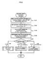
- Fig. 2 is a flowchart showing a motor drive control routine executed by the electronic control unit 40 in the motor control apparatus 20 of the embodiment. This control routine is repeatedly executed at preset time intervals (for example, at every 8 msec).
- the CPU 42 of the electronic control unit 40 first inputs the accelerator opening Acc from the accelerator pedal position sensor 34, the vehicle speed V from the vehicle speed sensor 24 , wheel speeds Vf and Vr from the wheel speed sensors 26a, 26b, 28a, and 28b, and a motor rotation speed Nm calculated from the rotation angle ⁇ measured by the rotation angle sensor 22 (step S100).
- the wheel speeds Vf and Vr respectively represent an average of the wheel speeds Vf1 and Vf2 measured by the wheel speed sensors 26a and 26b and an average of the wheel speeds Vr1 and Vr2 measured by the wheel speed sensors 28a and 28b.
- the vehicle speed V is measured by the vehicle speed sensor 24 in this embodiment, but may alternatively be calculated from the wheel speeds Vf1, Vf2, Vr1, and Vr2 measured by the wheel speed sensors 26a, 26b, 28a, and 28b.
- the CPU 42 sets a torque demand Tm* of the motor 12 according to the input accelerator opening Acc and the input vehicle speed V (step S102).
- a concrete procedure of setting the motor torque demand Tm* in this embodiment stores in advance variations in motor torque demand Tm* against the accelerator opening Acc and the vehicle speed V as a map in the ROM 44 and reads the motor torque demand Tm* corresponding to the given accelerator opening Acc and the given vehicle speed V from the map.
- This map is shown in Fig. 3.
- the CPU 42 subsequently calculates an angular acceleration ⁇ from the motor rotation speed Nm input at step S100 (step S104).
- the calculation of the angular acceleration ⁇ in this embodiment subtracts a previous rotation speed Nm input in a previous cycle of this routine from a current rotation speed Nm input in the current cycle of this routine (current rotation speed Nm - previous rotation speed Nm).
- the unit of the angular acceleration ⁇ is [rpm / 8 msec] since the execution interval of this routine is 8 msec in this embodiment, where the rotation speed Nm is expressed by the number of rotations per minute [rpm]. Any other suitable unit may be adopted for the angular acceleration ⁇ as long as the angular acceleration ⁇ is expressible as a time variation of rotation speed.
- the angular acceleration ⁇ may be an average of angular accelerations calculated in a preset number of cycles of this routine (for example, 3).
- the CPU 42 determines a skid state of the drive wheels 18a and 18b based on the calculated angular acceleration ⁇ (step S106), and executes a required series of control according to the result of the determination (steps S110 to S114), before terminating this motor drive control routine.
- the determination of no occurrence of a skid (when both a skid occurrence flag F1 and a skid convergence flag F2 described below are set equal to 0) triggers grip-state control (step S110).
- the determination of the occurrence of a skid (when the flag F1 is set equal to 1 and the flag F2 is set equal to 0) triggers skid occurring state control (step S112) to restrict the torque level output to the drive shaft.
- the determination of convergence of a skid (when both the flags F1 and F2 are set equal to 1) triggers skid convergence state control (step S114) to restore the restricted torque level output to the drive shaft.
- the determination of the skid state follows a skid state determination routine shown in Fig. 4.
- the CPU 42 of the electronic control unit 40 compares the angular acceleration ⁇ calculated at step S104 in the control routine of Fig. 2 with a preset threshold value ⁇ slip, which suggests the occurrence of a skid due to wheelspin (step S120).
- the CPU 42 determines the occurrence of a skid on the wheels 18a and 18b and sets the value '1' to a skid occurrence flag F1 representing the occurrence of a skid (step S122), in order to restrict the torque level output to the drive shaft.
- the CPU 42 then exits from this skid state determination routine.
- the CPU 42 determines whether the skid occurrence flag F1 is equal to 1 (step S124).
- the CPU 42 subsequently determines whether the current angular acceleration ⁇ is not less than 0 while the previous angular acceleration ⁇ in the previous cycle of this routine is less than 0, that is, whether the angular acceleration ⁇ rises from a negative value and passes over a zero cross point (step S126).
- the CPU 42 determines that the skid occurring on the drive wheels 18a and 18b is converged and that now is the adequate restoration timing of the restricted torque level output to the drive shaft and sets the value '1' to a skid convergence flag F2 (step S128). The CPU 42 then exits from this skid state determination routine.
- Fig. 5 shows a variation in angular acceleration ⁇ against time.
- the angular acceleration ⁇ in the course of restriction of the torque level output to the drive shaft in response to the occurrence of a skid, the angular acceleration ⁇ first increases with elapse of time to give a positive peak, then decreases to give a negative peak, and again increases.
- the adequate restoration timing of the restricted torque level output to the drive shaft is a zero cross point of the angular acceleration ⁇ after the negative peak.
- the zero cross timing enables the direction of the torque applied on the drive shaft in the course of restoration from the torque restriction to be completely identical with the direction of the angular acceleration ⁇ applied on the drive shaft, thus preventing potential torsional vibrations of the drive shaft.
- the CPU 42 determines that the skid has not yet been converged or that now is not the adequate restoration timing of the restricted torque level output to the drive shaft even under the condition of convergence of the skid and terminates this skid state determination routine.
- the CPU 42 sets both the skid occurrence flag F1 and the skid convergence flag F2 equal to 0 (step S130) and terminates this skid state determination routine.
- the respective controls executed according to the values of the skid occurrence flag F1 and the skid convergence flag F2 are described in detail below.
- the grip state control is normal drive control of the motor 12 and drives and controls the motor 12 to ensure output of a torque corresponding to the preset torque demand Tm*.
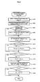
- the skid occurring state control drives and controls the motor 12 to lower the angular acceleration ⁇ , which was increased by the occurrence of a skid, and follows a skid occurring state control routine of Fig. 6.
- the CPU 42 of the electronic control unit 40 first compares the angular acceleration ⁇ with a preset peak value ⁇ peak (step S140). When the angular acceleration ⁇ exceeds the preset peak value ⁇ peak, the current value of the angular acceleration ⁇ is newly set to the peak value ⁇ peak (step S142).
- the peak value ⁇ peak represents a peak of the angular acceleration ⁇ increasing due to a skid and is initially set equal to 0.
- the peak value ⁇ peak is successively updated to the current value of the angular acceleration ⁇ .
- the maximum value of the increasing angular acceleration ⁇ is fixed to the peak value ⁇ peak.
- the CPU 42 sets a maximum torque Tmax as an upper limit of torque output from the motor 12 corresponding to the peak value ⁇ peak (step S144).
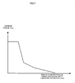
- the procedure of this embodiment refers to a map shown in Fig. 7 to set the maximum torque Tmax.
- Fig. 7 shows a variation in maximum torque Tmax against the angular acceleration ⁇ . As illustrated in this map, the maximum torque Tmax decreases with an increase in angular acceleration ⁇ .
- the greater peak value ⁇ peak with an increase in angular acceleration ⁇ that is, the heavier skid, sets the smaller value to the maximum torque Tmax and limits the output torque of the motor 12 to the smaller maximum torque Tmax.
- the motor torque demand Tm* is compared with the maximum torque Tmax (step S146). When the motor torque demand Tm* exceeds the maximum torque Tmax, the motor torque demand Tm* is limited to the maximum torque Tmax (step S148).
- the CPU 42 determines whether a torque restriction width (a torque variation) given as a difference between the current motor torque demand Tm* and a previous motor torque demand Tm* set in the previous cycle of this routine (Tm* - Previous Tm*) is in a preset allowable range (step S150). When the torque variation is not in the preset allowable range, the motor torque demand Tm* is regulated to limit the torque variation in the preset allowable range (step S152).
- Such regulation of the motor torque demand Tm* reduces a potential torque shock caused by significant restriction of the torque level output to the drive shaft in response to the occurrence of a skid.
- the CPU 42 sets the motor torque demand Tm* to a target torque and drives and controls the motor 12 to output a torque corresponding to the target torque Tm* (step S154), before exiting from this skid occurring state control routine.
- the torque output from the motor 12 in the occurrence of a skid is limited to a lower level (that is, the maximum torque Tmax corresponding to the peak value ⁇ peak of the angular acceleration in the map of Fig. 7) for immediate reduction of the skid. This limitation effectively reduces the skid.
- the skid convergence state control drives and controls the motor 12 to restore the limited torque level, when the torque restriction by the skid occurring state control lowers the angular acceleration ⁇ and converges the skid.
- the skid convergence state control follows a skid convergence state control routine of Fig. 8.
- the CPU 42 of the electronic control unit 40 first inputs a torque restoration limit ⁇ (expressed in the same unit [rpm / 8 msec] as the angular acceleration) (step S160).
- the torque restoration limit ⁇ is a parameter used to set a degree of restoration from the torque restriction by increasing the maximum torque Tmax, which has been set in the skid occurring state control described above.
- the initial value of the torque restoration limit ⁇ is set equal to 0.
- the torque restoration limit ⁇ is set according to a torque restoration limit ⁇ setting routine shown in Fig. 9 as discussed below.
- the torque restoration limit ⁇ setting routine of Fig. 9 is executed when the skid occurrence flag F1 is set from 0 to 1 (that is, when the calculated angular acceleration ⁇ exceeds the preset threshold value ⁇ slip) at step S122 in the skid state determination routine of Fig. 4.
- This routine inputs the motor rotation speed Nm calculated from the rotation angle ⁇ measured by the rotation angle sensor 22, calculates the angular acceleration ⁇ of the motor 12 from the input motor rotation speed Nm, and integrates the angular acceleration ⁇ to give a time integration ⁇ int thereof over an integration interval since the angular acceleration ⁇ exceeded the preset threshold value ⁇ slip. These input, calculation, and integration steps are repeated until the angular acceleration ⁇ decreases below the preset threshold value ⁇ slip (steps S190 to S196).
- Equation (1) the time integration ⁇ int of the angular acceleration ⁇ is given by Equation (1) below, where ⁇ t denotes a time interval of the repeated execution of steps S190 to S196 and is set equal to 8 msec in this embodiment: ⁇ int ⁇ ⁇ int + ( ⁇ - ⁇ slip) ⁇ ⁇ t
- the time integration ⁇ int of the angular acceleration ⁇ obtained by the processing of steps S190 to S196 is multiplied by a predetermined coefficient k to set the torque restoration limit ⁇ (step S198).
- the torque restoration limit ⁇ setting routine is here terminated.
- the concrete process of setting the torque restoration limit ⁇ writes the value of the torque restoration limit ⁇ into a specific area of the RAM 46.
- a torque restriction cancellation routine (not shown) is executed after elapse of a predetermined standby time since the start of execution of the skid convergence state control routine.
- the torque restriction cancellation routine sets a cancellation rate ⁇ to increment from zero by a fixed value on every elapse of a preset time period. Cancellation of the torque restoration limit ⁇ does not start until elapse of the predetermined standby time since the start of execution of the routine of Fig. 7.
- the CPU 42 subtracts the cancellation rate ⁇ from the torque restoration limit ⁇ input at step S160 to cancel the torque restoration limit ⁇ (step S166). In the event of no detection of a cancellation request, on the other hand, the torque restoration limit ⁇ input at step S160 is not cancelled.
- the CPU 42 then refers to the map of Fig. 7 and sets the maximum torque Tmax as an upper limit of torque output from the motor 12 corresponding to the torque restoration limit ⁇ (step S168).
- the CPU 42 determines whether a torque restriction rate ⁇ lock [rpm / 8 msec] has been set (step S170). Under the condition of setting the torque restriction rate ⁇ lock, the maximum torque Tmax is set corresponding to the torque restriction rate ⁇ lock by referring to the map of Fig. 7, regardless of the setting at step S168 (step S172).
- the torque restriction rate ⁇ lock is a parameter set to control the vibration of the drive shaft due to an abrupt negative change of the angular acceleration ⁇ , which arises when the vehicle 10 moves to a high ⁇ road after a skid on a low ⁇ road.
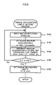
- the torque restriction rate ⁇ lock is set according to a torque restriction rate ⁇ lock setting routine of Fig. 10.
- the torque restriction rate ⁇ lock setting routine is executed when the skid occurrence flag F1 is set from 0 to 1.
- This routine inputs the motor rotation speed Nm calculated from the rotation angle ⁇ measured by the rotation angle sensor 22 and calculates the angular acceleration ⁇ from the input motor rotation speed Nm.
- the calculated angular acceleration ⁇ reaches a negative peak, that is, when a time difference of the angular acceleration ⁇ changes from negative to positive, the angular acceleration ⁇ at the moment is set to a negative peak value ⁇ peak2 (steps S200 to S206).
- is then compared with a predetermined threshold value ⁇ ref (step S208).
- Fig. 11 shows a variation in angular acceleration ⁇ against time under the condition of a change of the road surface condition.
- the negative peak appearing in the course of convergence of the wheelspin of the drive wheels 18a and 18b is in a preset range as shown in Fig. 5.
- the angular acceleration ⁇ has an abrupt negative change to make the negative peak exceed the preset range.
- a change of the road surface condition is accordingly assumed when the absolute negative peak value
- the torque restriction rate ⁇ lock is set corresponding to the absolute negative peak value
- the routine cancels the torque restriction rate ⁇ lock (step S204) and is terminated.
- a concrete procedure of setting the torque restriction rate ⁇ lock in this embodiment stores in advance a variation in torque restriction rate ⁇ lock against the absolute negative peak value
- One example of this map is shown in Fig. 12. As shown in the map of Fig.
- the torque restriction rate ⁇ lock increases with an increase in absolute negative peak value
- the smaller maximum torque Tmax is set against the greater torque restriction rate ⁇ lock (see Fig. 7), so that a smaller value is set to the maximum torque Tmax corresponding to the greater absolute negative peak value
- the torque restriction rate ⁇ lock is kept unchanged until elapse of the preset time period.
- the routine of Fig. 8 is repeatedly executed to effectuate the torque restriction with setting of the torque restriction rate ⁇ lock in the preset time period. The repeated execution in the preset time period effectively controls a potential vibration of the angular acceleration ⁇ (vibration of the driving system), which may arise in response to a change of the road surface condition.
- the preset time period may be an expected vibration convergence time measured experimentally.
- the solid line curve in Fig. 11 shows a time variation of the angular acceleration ⁇ under the condition of torque restriction with setting of the torque restriction rate ⁇ lock.
- the broken line curve shows a time variation of the angular acceleration ⁇ under the condition of no torque restriction with the torque restriction rate ⁇ lock.
- the procedure of this embodiment completely cancels out the setting of the torque restriction rate ⁇ lock at a time after elapse of the preset time period.
- One modified procedure may cancel the setting of the torque restriction rate ⁇ lock in a stepwise manner.
- the motor torque demand Tm* is compared with the preset maximum torque Tmax (step S174).
- the motor torque demand Tm* exceeds the maximum torque Tmax, the motor torque demand Tm* is limited to the maximum torque Tmax (step S176).
- the CPU 42 sets the motor torque demand Tm* to a target torque and drives and controls the motor 12 to output a torque corresponding to the target torque Tm* (step S178).
- the CPU 42 determines whether the torque restoration limit ⁇ 1 is not greater than zero, that is, whether the torque restoration limit ⁇ 1 has been cancelled out completely (step S180). In the event of perfect cancellation of the torque restoration limit ⁇ , both the slip occurrence flag F1 and the slip convergence flag F2 are reset to 0 (step S182).
- the motor control apparatus 20 of the embodiment restricts the torque level output to the drive shaft in response to detection of a skid caused by the wheelspin of the drive wheels 18a and 18b, and restores the restricted torque level at the zero cross timing of the angular acceleration ⁇ of the rotating shaft of the motor 12 after the negative peak value ⁇ peak 2.
- the torque control makes the direction of the torque completely identical with the direction of the angular acceleration.
- This arrangement desirably prevents potential torsional vibrations of the drive shaft and the vibration of the angular acceleration ⁇ .
- of the angular acceleration ⁇ reflecting a change of the road surface condition exceeds the predetermined threshold value ⁇ ref, the output torque level is restricted according to the negative peak value ⁇ peak2.
- This arrangement desirably prevents potential vibrations of the drive shaft due to a change of the road surface condition.
- the motor control apparatus 20 of the embodiment sets the motor torque demand Tm* to limit the torque variation in the specified allowable range, in the case where the torque variation is out of the specified allowable range in the course of restriction of the torque level output to the drive shaft in response to the occurrence of a skid due to the wheelspin of the drive wheels 18a and 18b.
- This arrangement effectively prevents an excess torque shock (vibration of the drive shaft), which may be caused by torque restriction in response to the occurrence of a skid.
- the motor control apparatus 20 of the embodiment restores the restricted torque level at the zero cross timing of the angular acceleration ⁇ of the rotating shaft of the motor 12.
- the restricted torque level may be restored at any timing when the direction of the torque is identical with the direction of the angular acceleration, that is, at any timing in the course of an increase in angular acceleration ⁇ after the negative peak value ⁇ peak2.
- the motor control apparatus 20 of the embodiment specifies the allowable range of torque variation and sets the motor torque demand Tm* to limit the torque variation in the specified allowable range in the course of restriction of the torque level output from the motor 12 in response to detection of a skid.
- One modified procedure may set the motor torque demand Tm* without specifying the allowable range.
- the motor control apparatus 20 of the embodiment reads the torque restriction rate ⁇ lock corresponding to the negative peak value ⁇ peak2 of the angular acceleration ⁇ from the map of Fig. 12, and sets the maximum torque Tmax corresponding to the torque restriction rate ⁇ lock in the map of Fig. 7 to attain torque restriction.
- One modified procedure may directly set the maximum torque Tmax corresponding to the negative peak value ⁇ peak2 of the angular acceleration ⁇ to attain torque restriction.
- the motor control apparatus 20 of the embodiment may adopt a leveling technique in the process of restricting the torque level output to the drive shaft and in the process of restoring the restricted torque level output to the drive shaft. This enhances the effect of controlling the transmission of vibrations to the drive shaft.
- the embodiment described above regards control of the motor 12, which is mounted on the vehicle 10 and is mechanically connected with the drive shaft linked to the drive wheels 18a and 18b to directly output power to the drive shaft.
- the technique of the invention is applicable to a vehicle of any other structure with a motor that is capable of directly outputting power to a drive shaft.
- one possible application of the invention is a series hybrid vehicle including an engine, a generator that is linked to an output shaft of the engine, a battery that is charged with electric power generated by the generator, and a motor that is mechanically connected with a drive shaft linked to drive wheels and is driven with a supply of electric power from the battery.
- a mechanical distribution-type hybrid vehicle 110 including an engine 111, a planetary gear 117 that is connected with the engine 111, a motor 113 that is connected with the planetary gear 117 and is capable of generating electric power, and a motor 112 that is also connected with the planetary gear 117 and is mechanically connected with a drive shaft linked to drive wheels to directly output power to the drive shaft, as shown in Fig. 13.
- Still another possible application of the invention is an electrical distribution-type hybrid vehicle 210 including a motor 213 that has an inner rotor 213a connected with an output shaft of an engine 211 and an outer rotor 213b connected with a drive shaft linked to drive wheels 218a and 218b and relatively rotates through electromagnetic interactions between the inner rotor 213a and the outer rotor 213b and a motor 212 that is mechanically connected with the drive shaft to directly output power to the drive shaft, as shown in Fig. 14.
- a hybrid vehicle 310 including an engine 311 that is connected with a drive shaft linked to drive wheels 318a and 318b via a transmission 314 (for example, a continuous variable transmission or an automatic transmission) and a motor 312 that is placed after the engine 311 and is connected with the drive shaft via the transmission 314 (or a motor that is directly connected with the drive shaft), as shown in Fig. 15.
- the torque control mainly controls the motor mechanically connected with the drive shaft, because of its high torque output response.
- the control of this motor may be combined with control of the other motor or with control of the engine.
- the technique of the invention is effectively applied to automobile and train-related industries.
Landscapes
- Engineering & Computer Science (AREA)
- Mechanical Engineering (AREA)
- Power Engineering (AREA)
- Transportation (AREA)
- Sustainable Energy (AREA)
- Sustainable Development (AREA)
- Life Sciences & Earth Sciences (AREA)
- Chemical & Material Sciences (AREA)
- Combustion & Propulsion (AREA)
- General Engineering & Computer Science (AREA)
- Electric Propulsion And Braking For Vehicles (AREA)
- Hybrid Electric Vehicles (AREA)
- Control Of Vehicle Engines Or Engines For Specific Uses (AREA)
Priority Applications (1)
| Application Number | Priority Date | Filing Date | Title |
|---|---|---|---|
| EP07003337A EP1787852B1 (fr) | 2002-08-29 | 2003-07-07 | Appareil de contrôle de moteur et procédé de contrôle de moteur |
Applications Claiming Priority (3)
| Application Number | Priority Date | Filing Date | Title |
|---|---|---|---|
| JP2002251365 | 2002-08-29 | ||
| JP2002251365A JP3772809B2 (ja) | 2002-08-29 | 2002-08-29 | 原動機の制御装置および原動機の制御方法 |
| PCT/JP2003/008594 WO2004022382A1 (fr) | 2002-08-29 | 2003-07-07 | Dispositif et procédé de commande d'un moteur premier |
Related Child Applications (1)
| Application Number | Title | Priority Date | Filing Date |
|---|---|---|---|
| EP07003337A Division EP1787852B1 (fr) | 2002-08-29 | 2003-07-07 | Appareil de contrôle de moteur et procédé de contrôle de moteur |
Publications (3)
| Publication Number | Publication Date |
|---|---|
| EP1547854A1 true EP1547854A1 (fr) | 2005-06-29 |
| EP1547854A4 EP1547854A4 (fr) | 2006-06-07 |
| EP1547854B1 EP1547854B1 (fr) | 2008-02-13 |
Family
ID=31972679
Family Applications (2)
| Application Number | Title | Priority Date | Filing Date |
|---|---|---|---|
| EP07003337A Expired - Lifetime EP1787852B1 (fr) | 2002-08-29 | 2003-07-07 | Appareil de contrôle de moteur et procédé de contrôle de moteur |
| EP03741239A Expired - Lifetime EP1547854B1 (fr) | 2002-08-29 | 2003-07-07 | Dispositif et procede de commande d'un moteur premier |
Family Applications Before (1)
| Application Number | Title | Priority Date | Filing Date |
|---|---|---|---|
| EP07003337A Expired - Lifetime EP1787852B1 (fr) | 2002-08-29 | 2003-07-07 | Appareil de contrôle de moteur et procédé de contrôle de moteur |
Country Status (7)
| Country | Link |
|---|---|
| US (1) | US7132806B2 (fr) |
| EP (2) | EP1787852B1 (fr) |
| JP (1) | JP3772809B2 (fr) |
| KR (1) | KR100632896B1 (fr) |
| CN (1) | CN1678473A (fr) |
| DE (2) | DE60319112T2 (fr) |
| WO (1) | WO2004022382A1 (fr) |
Cited By (2)
| Publication number | Priority date | Publication date | Assignee | Title |
|---|---|---|---|---|
| US7132806B2 (en) * | 2002-08-29 | 2006-11-07 | Toyota Jidosha Kabushiki Kaisha | Motor control apparatus and motor control method |
| US7230393B2 (en) * | 2002-08-29 | 2007-06-12 | Toyota Jidosha Kabushiki Kaisha | Motor control apparatus and motor control method |
Families Citing this family (24)
| Publication number | Priority date | Publication date | Assignee | Title |
|---|---|---|---|---|
| JP4172391B2 (ja) * | 2003-12-24 | 2008-10-29 | 株式会社デンソー | 車両統合制御システムおよびプログラム |
| JP4140529B2 (ja) * | 2004-02-03 | 2008-08-27 | 株式会社デンソー | 車両用制御装置 |
| JP4569266B2 (ja) * | 2004-11-09 | 2010-10-27 | 日産自動車株式会社 | 車両のモータトラクション制御装置 |
| CN100400332C (zh) * | 2004-11-17 | 2008-07-09 | 丰田自动车株式会社 | 车辆以及车辆的控制方法 |
| CN100400331C (zh) * | 2004-11-17 | 2008-07-09 | 丰田自动车株式会社 | 车辆以及车辆的控制方法 |
| US8335625B2 (en) | 2005-09-06 | 2012-12-18 | Nissan Motor Co., Ltd. | Slip control device and method for a vehicle |
| US8688299B2 (en) * | 2007-05-02 | 2014-04-01 | Nissan Motor Co., Ltd. | Mode change control system for hybrid vehicle |
| JP4281838B1 (ja) * | 2007-12-27 | 2009-06-17 | トヨタ自動車株式会社 | 車両のスリップ制御装置 |
| US8521384B2 (en) | 2008-01-28 | 2013-08-27 | Textron Innovations Inc. | Turf maintenance vehicle all-wheel drive system |
| US8253357B2 (en) * | 2008-09-15 | 2012-08-28 | Caterpillar Inc. | Load demand and power generation balancing in direct series electric drive system |
| US20110017529A1 (en) * | 2009-07-24 | 2011-01-27 | A Truly Electric Car Company | Truly electric car |
| EP2305554B1 (fr) * | 2009-09-23 | 2014-04-23 | ABB Oy | Procédé et agencement pour le fonctionnement d'une rampe de navire |
| US8265815B2 (en) * | 2009-11-25 | 2012-09-11 | GM Global Technology Operations LLC | Method for controlling output torque in powertrains |
| US8676417B2 (en) * | 2010-09-07 | 2014-03-18 | GM Global Technology Operations LLC | Output torque management in a vehicle having an electric powertrain |
| JP2012086709A (ja) * | 2010-10-21 | 2012-05-10 | Nissan Motor Co Ltd | 車両の駆動力制御装置 |
| US8777803B2 (en) | 2011-05-25 | 2014-07-15 | GM Global Technology Operations LLC | Method of prioritizing output torque and off-going clutch torque constraints during a torque phase |
| JP5879251B2 (ja) | 2012-12-14 | 2016-03-08 | 本田技研工業株式会社 | 電動機の駆動制御装置 |
| US9266445B2 (en) * | 2013-03-14 | 2016-02-23 | Boosted Inc. | Dynamic control for light electric vehicles |
| CN105946826B (zh) * | 2016-05-10 | 2018-07-06 | 南京理工大学 | 无需轮速信息的车辆防滑控制方法、控制系统以及车辆 |
| JP6990112B2 (ja) * | 2017-01-11 | 2022-01-12 | 公益財団法人鉄道総合技術研究所 | 再粘着制御方法および電動機制御装置 |
| US10793157B2 (en) * | 2017-05-24 | 2020-10-06 | Toyota Motor Engineering & Manufacturing North America, Inc. | Operating electrified vehicles during traction events |
| DE102019217322A1 (de) * | 2019-11-08 | 2021-05-12 | Zf Friedrichshafen Ag | Verfahren zum Betreiben eines Antriebsstrangs mit wenigstens einem Differenzial |
| CN111729298A (zh) * | 2020-06-22 | 2020-10-02 | 网易(杭州)网络有限公司 | 一种地图控制方法、装置、电子设备和存储介质 |
| CN112758096B (zh) * | 2021-02-19 | 2022-02-01 | 安徽安凯汽车股份有限公司 | 一种基于电机转矩控制的智能驱动防滑控制系统及方法 |
Citations (3)
| Publication number | Priority date | Publication date | Assignee | Title |
|---|---|---|---|---|
| US4035698A (en) * | 1973-04-06 | 1977-07-12 | Asea Aktiebolog | Means for counteracting slipping and skidding in a motor-driven rail-vehicle |
| US4075538A (en) * | 1976-05-19 | 1978-02-21 | General Electric Company | Adaptive acceleration responsive system |
| EP1147937A2 (fr) * | 2000-04-17 | 2001-10-24 | Toyota Jidosha Kabushiki Kaisha | Système d'antipatinage pour véhicules |
Family Cites Families (29)
| Publication number | Priority date | Publication date | Assignee | Title |
|---|---|---|---|---|
| JPS5039232B1 (fr) * | 1969-11-12 | 1975-12-15 | ||
| DE2901740A1 (de) * | 1978-01-18 | 1979-07-19 | Honda Motor Co Ltd | Antiblockierverfahren fuer fahrzeugraeder |
| JPS61218466A (ja) * | 1985-03-25 | 1986-09-27 | Nippon Denso Co Ltd | アンチスキツド制御装置 |
| JPH088728B2 (ja) * | 1985-08-14 | 1996-01-29 | 株式会社日立製作所 | 電気車の再粘着制御装置 |
| JPH089327B2 (ja) * | 1987-07-09 | 1996-01-31 | 住友電気工業株式会社 | アンチロックブレ−キ制御装置 |
| JP2600756B2 (ja) * | 1988-02-16 | 1997-04-16 | トヨタ自動車株式会社 | 車両の加速スリップ制御装置 |
| JP2934457B2 (ja) * | 1989-08-28 | 1999-08-16 | 富士重工業株式会社 | 4輪駆動車の不等トルク配分制御装置 |
| JP3032232B2 (ja) * | 1990-04-16 | 2000-04-10 | 日産自動車株式会社 | 車両の旋回挙動制御装置 |
| JP3324779B2 (ja) * | 1991-07-02 | 2002-09-17 | 本田技研工業株式会社 | 車両のトラクション制御方法 |
| JPH0687421A (ja) | 1992-09-07 | 1994-03-29 | Nissan Motor Co Ltd | 制動力制御装置 |
| JPH08182118A (ja) | 1994-12-22 | 1996-07-12 | Fuji Heavy Ind Ltd | 電気自動車の駆動制御装置 |
| JPH08182119A (ja) * | 1994-12-22 | 1996-07-12 | Toyota Motor Corp | 電気自動車用走行用モータの制御方法 |
| FR2744074B1 (fr) * | 1996-01-29 | 1998-03-20 | Smh Management Services Ag | Procede et dispositif de regulation commune de plusieurs moteurs electriques entrainant les roues motrices d'un vehicule automobile |
| JPH11511093A (ja) * | 1996-04-29 | 1999-09-28 | ローベルト ボツシユ ゲゼルシヤフト ミツト ベシユレンクテル ハフツング | 駆動トルクの調整のための方法及び装置 |
| AU738539B2 (en) * | 1997-09-24 | 2001-09-20 | Hitachi Limited | Controller for electric vehicles |
| DE19913824B4 (de) * | 1999-03-26 | 2010-04-01 | Robert Bosch Gmbh | Verfahren und Vorrichtung zur Steuerung einer Antriebseinheit |
| JP2001048000A (ja) * | 1999-08-10 | 2001-02-20 | Nisshinbo Ind Inc | アンチロックブレーキ制御装置 |
| JP4042277B2 (ja) * | 1999-11-29 | 2008-02-06 | アイシン精機株式会社 | 車体横すべり角推定装置 |
| JP2001177907A (ja) * | 1999-12-13 | 2001-06-29 | Hitachi Ltd | 電気車の制御装置 |
| DE19963748A1 (de) * | 1999-12-30 | 2001-07-12 | Bosch Gmbh Robert | Vorrichtung und Verfahren zur Regelung des Radschlupfes |
| JP2001342878A (ja) * | 2000-06-02 | 2001-12-14 | Toyota Motor Corp | 内燃機関の制御装置 |
| JP2002274358A (ja) * | 2001-03-23 | 2002-09-25 | Unisia Jecs Corp | アンチスキッド制御装置 |
| US6490518B1 (en) * | 2001-06-29 | 2002-12-03 | General Motors Corporation | Anti-lock brake control method having adaptive exit criteria |
| US6895322B2 (en) * | 2001-10-15 | 2005-05-17 | General Motors Corporation | Anti-lock brake control method having adaptive entry criteria |
| JP3772809B2 (ja) * | 2002-08-29 | 2006-05-10 | トヨタ自動車株式会社 | 原動機の制御装置および原動機の制御方法 |
| JP3772815B2 (ja) * | 2002-09-20 | 2006-05-10 | トヨタ自動車株式会社 | 車両のスリップ制御装置及びその制御方法 |
| US6728621B1 (en) * | 2002-10-04 | 2004-04-27 | General Motors Corporation | Anti-lock braking system controller for adjusting slip thresholds on inclines |
| JP3964771B2 (ja) * | 2002-10-11 | 2007-08-22 | 株式会社豊田中央研究所 | 路面状態推定装置、及び該装置を備えた車両の運動制御装置 |
| US6885930B2 (en) * | 2003-07-31 | 2005-04-26 | Siemens Energy & Automation, Inc. | System and method for slip slide control |
-
2002
- 2002-08-29 JP JP2002251365A patent/JP3772809B2/ja not_active Expired - Fee Related
-
2003
- 2003-07-07 US US10/525,798 patent/US7132806B2/en not_active Expired - Fee Related
- 2003-07-07 WO PCT/JP2003/008594 patent/WO2004022382A1/fr active IP Right Grant
- 2003-07-07 DE DE60319112T patent/DE60319112T2/de not_active Expired - Lifetime
- 2003-07-07 EP EP07003337A patent/EP1787852B1/fr not_active Expired - Lifetime
- 2003-07-07 DE DE60329871T patent/DE60329871D1/de not_active Expired - Lifetime
- 2003-07-07 KR KR1020057003380A patent/KR100632896B1/ko not_active IP Right Cessation
- 2003-07-07 EP EP03741239A patent/EP1547854B1/fr not_active Expired - Lifetime
- 2003-07-07 CN CNA038200791A patent/CN1678473A/zh active Pending
Patent Citations (3)
| Publication number | Priority date | Publication date | Assignee | Title |
|---|---|---|---|---|
| US4035698A (en) * | 1973-04-06 | 1977-07-12 | Asea Aktiebolog | Means for counteracting slipping and skidding in a motor-driven rail-vehicle |
| US4075538A (en) * | 1976-05-19 | 1978-02-21 | General Electric Company | Adaptive acceleration responsive system |
| EP1147937A2 (fr) * | 2000-04-17 | 2001-10-24 | Toyota Jidosha Kabushiki Kaisha | Système d'antipatinage pour véhicules |
Non-Patent Citations (1)
| Title |
|---|
| See also references of WO2004022382A1 * |
Cited By (2)
| Publication number | Priority date | Publication date | Assignee | Title |
|---|---|---|---|---|
| US7132806B2 (en) * | 2002-08-29 | 2006-11-07 | Toyota Jidosha Kabushiki Kaisha | Motor control apparatus and motor control method |
| US7230393B2 (en) * | 2002-08-29 | 2007-06-12 | Toyota Jidosha Kabushiki Kaisha | Motor control apparatus and motor control method |
Also Published As
| Publication number | Publication date |
|---|---|
| US20060175997A1 (en) | 2006-08-10 |
| CN1678473A (zh) | 2005-10-05 |
| WO2004022382A1 (fr) | 2004-03-18 |
| US7132806B2 (en) | 2006-11-07 |
| JP3772809B2 (ja) | 2006-05-10 |
| EP1787852A3 (fr) | 2007-08-22 |
| KR20050057008A (ko) | 2005-06-16 |
| EP1787852B1 (fr) | 2009-10-28 |
| JP2004096825A (ja) | 2004-03-25 |
| KR100632896B1 (ko) | 2006-10-11 |
| EP1787852A2 (fr) | 2007-05-23 |
| DE60319112T2 (de) | 2009-02-05 |
| EP1547854B1 (fr) | 2008-02-13 |
| DE60319112D1 (de) | 2008-03-27 |
| DE60329871D1 (de) | 2009-12-10 |
| EP1547854A4 (fr) | 2006-06-07 |
Similar Documents
| Publication | Publication Date | Title |
|---|---|---|
| EP1787852B1 (fr) | Appareil de contrôle de moteur et procédé de contrôle de moteur | |
| EP1552977B1 (fr) | Procede et dispositif de commande d'un moteur premier | |
| US9783182B2 (en) | Control method for front and rear wheel torque distribution of electric 4 wheel drive hybrid electric vehicle | |
| JP3610969B2 (ja) | 四輪駆動車両の駆動力制御装置 | |
| US7596444B2 (en) | Vehicle skid control device, automobile with vehicle skid control device mounted thereon, and vehicle skid control method | |
| US7451847B2 (en) | Vehicle control method | |
| EP1548253B1 (fr) | Dispositif de commande de vehicule, vehicule equipe de ce dispositif et procede de commande du vehicule equipe | |
| EP1654138B1 (fr) | Systeme et procede de regulation de glissement de vehicule | |
| US7230393B2 (en) | Motor control apparatus and motor control method | |
| KR20210014821A (ko) | 차량의 휠 슬립 제어 방법 | |
| CN111114523A (zh) | 使混合动力电动车辆运行的驱动扭矩指令产生装置和方法 | |
| US20050246087A1 (en) | Device, method, and car for estimating variation of state of road surface | |
| EP1533171B1 (fr) | Dispositif de commande de la traction d'un véhicule | |
| JP4089608B2 (ja) | 自動車 | |
| JP4103505B2 (ja) | 電気自動車およびこれに搭載された電動機の制御方法 | |
| KR100618506B1 (ko) | 차량 구동력 제어 장치 | |
| KR20210018652A (ko) | 차량의 휠 슬립 제어 방법 | |
| JP2004096939A (ja) | 自動車および自動車の制御装置 | |
| JP2003193877A (ja) | 車両の駆動力制御装置 | |
| JP2006129584A (ja) | トラクション制御装置 | |
| JP3536845B2 (ja) | 車両の駆動力制御装置 |
Legal Events
| Date | Code | Title | Description |
|---|---|---|---|
| PUAI | Public reference made under article 153(3) epc to a published international application that has entered the european phase |
Free format text: ORIGINAL CODE: 0009012 |
|
| 17P | Request for examination filed |
Effective date: 20050225 |
|
| AK | Designated contracting states |
Kind code of ref document: A1 Designated state(s): DE FR |
|
| A4 | Supplementary search report drawn up and despatched |
Effective date: 20060508 |
|
| 17Q | First examination report despatched |
Effective date: 20061005 |
|
| GRAP | Despatch of communication of intention to grant a patent |
Free format text: ORIGINAL CODE: EPIDOSNIGR1 |
|
| GRAS | Grant fee paid |
Free format text: ORIGINAL CODE: EPIDOSNIGR3 |
|
| GRAA | (expected) grant |
Free format text: ORIGINAL CODE: 0009210 |
|
| AK | Designated contracting states |
Kind code of ref document: B1 Designated state(s): DE FR |
|
| REF | Corresponds to: |
Ref document number: 60319112 Country of ref document: DE Date of ref document: 20080327 Kind code of ref document: P |
|
| PLBE | No opposition filed within time limit |
Free format text: ORIGINAL CODE: 0009261 |
|
| STAA | Information on the status of an ep patent application or granted ep patent |
Free format text: STATUS: NO OPPOSITION FILED WITHIN TIME LIMIT |
|
| 26N | No opposition filed |
Effective date: 20081114 |
|
| REG | Reference to a national code |
Ref country code: DE Ref legal event code: R084 Ref document number: 60319112 Country of ref document: DE Effective date: 20111109 |
|
| PGFP | Annual fee paid to national office [announced via postgrant information from national office to epo] |
Ref country code: DE Payment date: 20140702 Year of fee payment: 12 |
|
| PGFP | Annual fee paid to national office [announced via postgrant information from national office to epo] |
Ref country code: FR Payment date: 20140708 Year of fee payment: 12 |
|
| REG | Reference to a national code |
Ref country code: DE Ref legal event code: R119 Ref document number: 60319112 Country of ref document: DE |
|
| PG25 | Lapsed in a contracting state [announced via postgrant information from national office to epo] |
Ref country code: DE Free format text: LAPSE BECAUSE OF NON-PAYMENT OF DUE FEES Effective date: 20160202 |
|
| REG | Reference to a national code |
Ref country code: FR Ref legal event code: ST Effective date: 20160331 |
|
| PG25 | Lapsed in a contracting state [announced via postgrant information from national office to epo] |
Ref country code: FR Free format text: LAPSE BECAUSE OF NON-PAYMENT OF DUE FEES Effective date: 20150731 |