EP1538359A1 - Butée de débrayage - Google Patents
Butée de débrayage Download PDFInfo
- Publication number
- EP1538359A1 EP1538359A1 EP04028689A EP04028689A EP1538359A1 EP 1538359 A1 EP1538359 A1 EP 1538359A1 EP 04028689 A EP04028689 A EP 04028689A EP 04028689 A EP04028689 A EP 04028689A EP 1538359 A1 EP1538359 A1 EP 1538359A1
- Authority
- EP
- European Patent Office
- Prior art keywords
- ball bearing
- sleeve
- side plate
- self
- centering
- Prior art date
- Legal status (The legal status is an assumption and is not a legal conclusion. Google has not performed a legal analysis and makes no representation as to the accuracy of the status listed.)
- Withdrawn
Links
Images

Classifications
-
- F—MECHANICAL ENGINEERING; LIGHTING; HEATING; WEAPONS; BLASTING
- F16—ENGINEERING ELEMENTS AND UNITS; GENERAL MEASURES FOR PRODUCING AND MAINTAINING EFFECTIVE FUNCTIONING OF MACHINES OR INSTALLATIONS; THERMAL INSULATION IN GENERAL
- F16D—COUPLINGS FOR TRANSMITTING ROTATION; CLUTCHES; BRAKES
- F16D23/00—Details of mechanically-actuated clutches not specific for one distinct type
- F16D23/12—Mechanical clutch-actuating mechanisms arranged outside the clutch as such
- F16D23/14—Clutch-actuating sleeves or bearings; Actuating members directly connected to clutch-actuating sleeves or bearings
- F16D23/142—Clutch-actuating sleeves or bearings; Actuating members directly connected to clutch-actuating sleeves or bearings with a resilient member acting radially between the bearing and its guide means
-
- F—MECHANICAL ENGINEERING; LIGHTING; HEATING; WEAPONS; BLASTING
- F16—ENGINEERING ELEMENTS AND UNITS; GENERAL MEASURES FOR PRODUCING AND MAINTAINING EFFECTIVE FUNCTIONING OF MACHINES OR INSTALLATIONS; THERMAL INSULATION IN GENERAL
- F16C—SHAFTS; FLEXIBLE SHAFTS; ELEMENTS OR CRANKSHAFT MECHANISMS; ROTARY BODIES OTHER THAN GEARING ELEMENTS; BEARINGS
- F16C27/00—Elastic or yielding bearings or bearing supports, for exclusively rotary movement
- F16C27/06—Elastic or yielding bearings or bearing supports, for exclusively rotary movement by means of parts of rubber or like materials
- F16C27/066—Ball or roller bearings
-
- F—MECHANICAL ENGINEERING; LIGHTING; HEATING; WEAPONS; BLASTING
- F16—ENGINEERING ELEMENTS AND UNITS; GENERAL MEASURES FOR PRODUCING AND MAINTAINING EFFECTIVE FUNCTIONING OF MACHINES OR INSTALLATIONS; THERMAL INSULATION IN GENERAL
- F16C—SHAFTS; FLEXIBLE SHAFTS; ELEMENTS OR CRANKSHAFT MECHANISMS; ROTARY BODIES OTHER THAN GEARING ELEMENTS; BEARINGS
- F16C19/00—Bearings with rolling contact, for exclusively rotary movement
- F16C19/02—Bearings with rolling contact, for exclusively rotary movement with bearing balls essentially of the same size in one or more circular rows
- F16C19/14—Bearings with rolling contact, for exclusively rotary movement with bearing balls essentially of the same size in one or more circular rows for both radial and axial load
- F16C19/16—Bearings with rolling contact, for exclusively rotary movement with bearing balls essentially of the same size in one or more circular rows for both radial and axial load with a single row of balls
- F16C19/163—Bearings with rolling contact, for exclusively rotary movement with bearing balls essentially of the same size in one or more circular rows for both radial and axial load with a single row of balls with angular contact
-
- F—MECHANICAL ENGINEERING; LIGHTING; HEATING; WEAPONS; BLASTING
- F16—ENGINEERING ELEMENTS AND UNITS; GENERAL MEASURES FOR PRODUCING AND MAINTAINING EFFECTIVE FUNCTIONING OF MACHINES OR INSTALLATIONS; THERMAL INSULATION IN GENERAL
- F16C—SHAFTS; FLEXIBLE SHAFTS; ELEMENTS OR CRANKSHAFT MECHANISMS; ROTARY BODIES OTHER THAN GEARING ELEMENTS; BEARINGS
- F16C2361/00—Apparatus or articles in engineering in general
- F16C2361/43—Clutches, e.g. disengaging bearing
Definitions
- the invention relates to a self-centering ball bearing unit for clutch release, located between an engine and a transmission and transmits or blocks the force from the former to the latter.
- a ball bearing unit is for clutch release between the engine (drive shaft 59) of a car with manual Transmission and the transmission 52 arranged; she is from the with the service coupled to the clutch pedal (not shown) swinging fork 54 pressed to release, moved on the front cover 53 toward the engine and temporarily blocks the transmission of torque functionally of the engine to the transmission 52 from.
- the clutch pedal Swings the fork 54 counterclockwise and pushes the ball bearing A. by the contact with the side plate axially to the engine.
- This ball bearing unit A for clutch release e.g. those shown in Fig.7 Unit used.
- This ball bearing unit mainly consists of a sleeve 1 made of plastic, a side plate 2 and a ball bearing 3, the is resiliently pressed by the spring means 4 against the side plate 2.
- the Rings of the ball bearing 3 are made of sheet steel by the compression deformation formed and the side plate 2 is integrated with the sleeve 1 made of plastic educated. (see Tokukaihei-270584).
- the bore of the side plate 2 deforms to the oval because of the load of two points of the fork tips. Concretely speaking it deforms by several dozen contrary to the condition without load.
- the integrally formed with the side plate 2 sleeve 1 also deforms under the influence of the bending of the side plate 2. If this strain too is large, the sleeve 1 remains on the front cover during the displacement of the sleeve. 1 Hang and the clutch may be difficult to operate.
- the main object of the invention is to form the sleeve so that it does not deform when the side plate is loaded by the fork tip becomes.
- the self-centering ball bearing unit for clutch release is provided with a ball bearing, which is the point of contact for Touching with the rotating parts of the coupling device comprises a sleeve Plastic, which is located inside the ball bearing, a press-formed Side plate made of sheet steel, which extends from the jacket of the sleeve to the outside, touched radially displaceable with the ball bearing on one axial side and with the release fork on the other side touched and a spring means, the the ball bearing presses elastically against the side plate; it is characterized that the sleeve and the side plate are separated.
- the outer ring is formed of sheet steel and an inwardly aligning Flange identifies and the spring means between the sleeve and the Flange is located, the flange of the outer ring by the pressure force of the spring means pressed against the side plate elastically and the ball bearing is in radially displaceable state held elastically.
- a spring can be placed between the side plate and the sleeve. This may cause the sleeve to tilt relative to the side plate, leaving itself The sleeve can always move along the front cover. Therefore, the Uneven wear and / or metallic adhesion can be avoided.
- the spring means plate spring, wave spring, rubber, etc. may be mentioned become.
- a means that the Avoids twist in between can be provided e.g. such a Avoidance mechanism, on the one hand a recess and on the other hand a projection are provided and engage with each other.
- the bad influence that the bore at the load deformed, thereby excluding that integrated with the sleeve Side plate is formed separately.
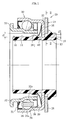
- the self-centering ball-bearing unit for clutch release which in the 1 is the same as the ball bearing unit A in Fig.6. She is between the engine (drive shaft 59) of the car with manual transmission and the transmission 52, moves axially on the front cover 53 to the motor side by operating the fork 54, and temporarily locks the Transmission of the rotational force of the engine to the transmission 52 from.
- the ball bearing unit for clutch release consists of a sleeve 10, a side plate 20, as main components a ball bearing 30 and a spring means 40.
- spring means here is a Disc spring shown.
- the sleeve 10 is an approximately cylindrical shaped body (injection molding, etc.).
- the Bore 12 of the sleeve 10 is slidably mounted on the front cover 53.
- a cone-shaped Guide surface 16 is formed, an outwardly projecting stop 18 formed in the middle (closer to the other side), and a side plate is projecting formed on the other side integrated.
- the guide surface 16 has the function to guide the bore of the diaphragm spring 40 when the out of the Ball bearing 30 and the diaphragm spring 40 existing intermediate unit on the Jacket 14 of the sleeve 10 is mounted.
- the stop 18 has the function that the shift from the installed state while gripping with the bore the plate spring 40 is avoided.
- the width of the stop 18 is narrow, one side is an obtuse oblique wall and the other side is a vertical wall or about angled oblique wall, with the hole the diaphragm spring 40 engages.
- One side has the function during assembly to guide the bore of the plate spring 40.
- At the lowest point of the wall of the the other side is a circumferential groove, and the depth this groove is slightly lower than that of the jacket 14.
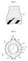
- the side plate 20 is a press-formed annular body made of sheet steel (see 3) and is integrated around the jacket of the other side of the sleeve 10. With a side surface 22 of the side plate 20, the flange 35 touches the outer ring 34 of the ball bearing 30 slidably in the radial direction. At the other side surface are the contact points with the fork 54 24 each at, for example, 180 ° opposite place arranged.
- the cementing-nitriding treatment for curing the Surfaces performed after the side plate 20 of cold drawn Sheet steel such as e.g. SPCC sheet steel by press molding in specified form was edited. As shown by numeral 26 in Fig.1 or Fig.4, the Peripheral edge of the side plate 20 except the contact point 24, with the Fork 54 touched, bent to the ball bearing side 30. Therefore, the compression and increase the strength of the side plate 20 is provided.
- the ball bearing 30 consists of an inner ring 32 as main components, an outer ring 34, balls 36, a cage 38 and shrouds 31, 39.
- Der Inner ring 32 is formed by pressing from sheet steel, and consists of a essentially in the axial direction extending part and a substantially radially outwardly extending part.
- a raceway 32a is formed on the outer coat of the essential in the axial direction extending part.
- the substantially radially outwardly extending part is as a brim 33 formed, which contacts with the diaphragm spring (55).
- the outer ring 34th is formed by pressing from sheet steel, and consists of a substantially in the axial direction extending part and a substantially radially inwardly extending flange portion 35.
- a raceway 34a is formed inside the bore of the substantially in the axial direction extending part. Between the inner ring 32 and the outer ring 34 are the majority the balls 36 which each contact the raceways 32a, 34a angled. The Balls 36 are by a cage 38 in the circumferential direction with certain Distance kept. On the one hand, a first cover plate 31 and on the other a second cover plate 39 is provided, which closes the gap between the Sheath of the inner ring 32 and the bore of the outer ring 34 seal.
- the first cover plate 31 is an elastic cover plate of non-touching type caused by the impressions of the outer shell is fixed in the one-sided bore of the outer ring 34.
- Their inside Lippe approaches the one-sided shell of the inner ring 32 with the Labyrinth clearance.
- the second cover plate 39 whose section is approximately angled C-shape, is a pressed sheet steel cover plate, which by the impressions of the outer shell in the other side bore of the outer ring 34 is attached; the inside edge approaches the other side Shell of the inner ring 32 with the labyrinth scope.
- first and / or second cover can also be known for bearings cover plates used by the touching type.
- the inner ring 32 is made of sheet steel e.g. by the process of pressing, Heat treatment, grinding of the raceway 32a and the cover disc location produced.
- the raw material of the steel sheet may be the cementable steel sheet and as a heat treatment, cementing heat treatment may be used become.
- cementable steels can nickel-chromium steel (SNC), nickel-chromium-molybdenum steel (SNCM), chrome steel (SCr) and chrome molybdenum steel (SCM).
- SNC nickel-chromium steel
- SNCM nickel-chromium-molybdenum steel
- SCM chrome molybdenum steel
- For nickel-chromium steel (SNC) and nickel-chromium-molybdenum steel (SNCM) of these steels seldom causes overcementing and they are also good material in mechanical property. However, they contain as an alloying element the costly nickel, so that they have problems in terms of cost.
- Inner rings 32 If required for inner rings mechanical property is considered, could be SNC steel or SNCM steel can be over-quality and can not be offset with cost become. In contrast, chromium molybdenum steel (SCM) rarely occurs the over-cementing and he has good deterrent property. Furthermore it is relatively cheaper compared to SNC steel or SNCM steel.
- SCM chromium-molybdenum steel
- the for inner rings the ball bearing unit required mechanical property is sufficiently fulfilled. For these reasons is preferably used as material for Inner rings 32 uses the chromium-molybdenum steel (SCM). In the chromium-molybdenum steels (SCM) there is SCM415 after contained carbon, SCM418, SCM420, SCM421 and SCM822, and the SCM415 thereof is on vorteilhaftesten.
- the ball bearing 30 is between the outer shell 14 of the sleeve 10 and the one-sided side surface 22 of the side plate 20, and by plate spring 40 held elastic as a spring means.
- the plate spring 40 is conical in section produced by pressing, with a majority of the cut out of the Hole is cut out cut out, and with majority of between side by side lying cutouts regularly on the circumference intended. As shown in Fig.1, the plate spring 40 shows because the elastic deformation the cone-angled cylindrical shape, depending on the elastic Deformation of the tongue increases or decreases the bore of the diaphragm spring 40th
- a radial clearance S 1 Between the outer shell 14 of the sleeve 10 and the bore of the inner ring 32 of the ball bearing 30 is a radial clearance S 1 , and between the bore of the flange 35 of the outer ring 34 and the outer shell 14 of the sleeve 10 is radial clearance S 2nd The radial clearance S 2 is smaller than the radial clearance S 1 (S 1 > S 2 ).
- the flange 35 of the outer ring 34 is pressed against the side surface 22 of the side plate 20 elastically; and the ball bearing 30 is elastically held between the outer shell 14 of the sleeve 10 and the side surface 22 of the side plate 20 in the radially displaceable state.
- the ball bearing 30 may be displaced in the radial direction for centering due to the existence of the radial clearance S 1 and S 2 to the sleeve 10 and the side plate 20, and the displacement for centering is limited by the smaller radial clearance S 2 .
- a rotational stop between the Sleeve 10 and the side plate 20 are provided. As shown in Fig. 2, are on the one hand a recess 28 on the side plate 20 and on the other hand, a projection 19 formed on the sleeve 10, and the two interlock. Therefore for example, the sleeve 10 and the side plate 20 can move relatively axially, but not in the circumferential direction.
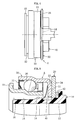
- FIG 5 shows an embodiment of the embodiment, wherein between the sleeve 10th and the side plate 20, a spring means 42 is clamped.
- the sleeve 10 tend to the side plate 20, and the sleeve 10 may be thereby move along the front cover 53. That is why it is possible to To avoid uneven wear and / or metallic sticking.
- the force from the spring means 40 and the force of Spring means means 42 are approximately equal.
- the ball bearing unit with the seal according to the invention not limited by the above-described embodiment, and may be within the meaning of the invention in various modifications and / or variants be executed.
Landscapes
- Engineering & Computer Science (AREA)
- General Engineering & Computer Science (AREA)
- Mechanical Engineering (AREA)
- Mechanical Operated Clutches (AREA)
- Support Of The Bearing (AREA)
- Rolling Contact Bearings (AREA)
Applications Claiming Priority (2)
| Application Number | Priority Date | Filing Date | Title |
|---|---|---|---|
| JP2003405005A JP2005163943A (ja) | 2003-12-03 | 2003-12-03 | クラッチレリーズ軸受 |
| JP2003405005 | 2003-12-03 |
Publications (1)
| Publication Number | Publication Date |
|---|---|
| EP1538359A1 true EP1538359A1 (fr) | 2005-06-08 |
Family
ID=34463984
Family Applications (1)
| Application Number | Title | Priority Date | Filing Date |
|---|---|---|---|
| EP04028689A Withdrawn EP1538359A1 (fr) | 2003-12-03 | 2004-12-03 | Butée de débrayage |
Country Status (2)
| Country | Link |
|---|---|
| EP (1) | EP1538359A1 (fr) |
| JP (1) | JP2005163943A (fr) |
Cited By (4)
| Publication number | Priority date | Publication date | Assignee | Title |
|---|---|---|---|---|
| DE102005032676A1 (de) * | 2005-07-13 | 2007-01-25 | Schaeffler Kg | Kupplungsausrücklager im Kontakt mit einer Tellerfeder |
| EP2017491A1 (fr) | 2007-07-20 | 2009-01-21 | SNR Roulements | Procédé de fabrication et rondelle d'autocentrage renforcée mécaniquement |
| WO2015043589A3 (fr) * | 2013-09-26 | 2015-11-26 | Schaeffler Technologies AG & Co. KG | Agencement de ressort pour un dispositif d'actionnement hydraulique |
| RU184971U1 (ru) * | 2018-08-30 | 2018-11-15 | Общество с ограниченной ответственностью "Валео Сервис" | Муфта выключения сцепления |
Families Citing this family (3)
| Publication number | Priority date | Publication date | Assignee | Title |
|---|---|---|---|---|
| JP4761208B2 (ja) * | 2006-08-03 | 2011-08-31 | 日本精工株式会社 | 軸受装置 |
| DE102007061589B4 (de) | 2007-01-29 | 2017-06-22 | Nsk Ltd. | Kugellager und Halterungskonstruktion |
| JP5045123B2 (ja) * | 2007-01-29 | 2012-10-10 | 日本精工株式会社 | 玉軸受及び支持構造 |
Citations (3)
| Publication number | Priority date | Publication date | Assignee | Title |
|---|---|---|---|---|
| DE2457353A1 (de) * | 1974-12-04 | 1976-06-10 | Schaeffler Ohg Industriewerk | Kupplungsausruecklager fuer kraftfahrzeuge |
| FR2465120A1 (fr) * | 1979-09-10 | 1981-03-20 | Ferodo Sa | Butee de debrayage |
| JPH0270584A (ja) | 1988-09-05 | 1990-03-09 | Honda Motor Co Ltd | 自動二輪車用スタンド装置 |
-
2003
- 2003-12-03 JP JP2003405005A patent/JP2005163943A/ja not_active Withdrawn
-
2004
- 2004-12-03 EP EP04028689A patent/EP1538359A1/fr not_active Withdrawn
Patent Citations (3)
| Publication number | Priority date | Publication date | Assignee | Title |
|---|---|---|---|---|
| DE2457353A1 (de) * | 1974-12-04 | 1976-06-10 | Schaeffler Ohg Industriewerk | Kupplungsausruecklager fuer kraftfahrzeuge |
| FR2465120A1 (fr) * | 1979-09-10 | 1981-03-20 | Ferodo Sa | Butee de debrayage |
| JPH0270584A (ja) | 1988-09-05 | 1990-03-09 | Honda Motor Co Ltd | 自動二輪車用スタンド装置 |
Cited By (7)
| Publication number | Priority date | Publication date | Assignee | Title |
|---|---|---|---|---|
| DE102005032676A1 (de) * | 2005-07-13 | 2007-01-25 | Schaeffler Kg | Kupplungsausrücklager im Kontakt mit einer Tellerfeder |
| US8286775B2 (en) | 2005-07-13 | 2012-10-16 | Schaeffler Technologies AG & Co. KG | Clutch release bearing in contact with a disk spring |
| DE102005032676B4 (de) * | 2005-07-13 | 2013-01-03 | Schaeffler Technologies AG & Co. KG | Kupplungsausrücklager im Kontakt mit einer Tellerfeder |
| EP2017491A1 (fr) | 2007-07-20 | 2009-01-21 | SNR Roulements | Procédé de fabrication et rondelle d'autocentrage renforcée mécaniquement |
| FR2919033A1 (fr) * | 2007-07-20 | 2009-01-23 | Snr Roulements Sa | Procede de fabrication et rondelle d'autocentrage renforcee mecaniquement |
| WO2015043589A3 (fr) * | 2013-09-26 | 2015-11-26 | Schaeffler Technologies AG & Co. KG | Agencement de ressort pour un dispositif d'actionnement hydraulique |
| RU184971U1 (ru) * | 2018-08-30 | 2018-11-15 | Общество с ограниченной ответственностью "Валео Сервис" | Муфта выключения сцепления |
Also Published As
| Publication number | Publication date |
|---|---|
| JP2005163943A (ja) | 2005-06-23 |
Similar Documents
| Publication | Publication Date | Title |
|---|---|---|
| EP1937991B1 (fr) | Cylindre recepteur avec piston annulaire presentant un jeu axial | |
| DE602004000188T2 (de) | Ausrücksvorrichtung und Montageverfahren | |
| DE102006012016B4 (de) | Kupplungsausrücklagervorrichtung | |
| DE112008002486T5 (de) | Lagerungsvorrichtung für Rad und Achsenmodul | |
| DE3012019A1 (de) | Kupplung, insbesondere fuer kraftfahrzeuge | |
| DE4418284B4 (de) | Drehschwingungsdämpfer-Doppelschwungrad, insbesondere für Kraftfahrzeuge | |
| DE112009003458T5 (de) | Kupplungslager, Kupplungsantriebsvorrichtung und ein mit diesen Elementen ausgestattetes Kraftfahrzeug | |
| DE4326404B4 (de) | Reibungskupplungsvorrichtung, insbesondere für ein Kraftfahrzeug, und elastische Membranfeder für eine solche Kupplungsvorrichtung | |
| DE60003477T2 (de) | Kupplungsausrücklager | |
| EP3030802B1 (fr) | Embrayage à friction équipée d'un moyen d'actionnement | |
| EP1538359A1 (fr) | Butée de débrayage | |
| DE202006008940U1 (de) | Kupplungsausrücklagervorrichtung | |
| DE102017206513A1 (de) | Gelenkwelle | |
| DE2250455A1 (de) | Paarung eines kupplungshebels mit der stirnseite eines kupplungslagers | |
| DE69818363T2 (de) | Kupplungsausrücklager mit angesetzter Anschlagsdruckplatte | |
| DE4430249C2 (de) | Kupplungsabdeckungsausbildung mit einer Tellerfeder | |
| DE2630656A1 (de) | Kugellager-ausruecker, insbesondere fuer kraftfahrzeugkupplungen | |
| DE102014212165A1 (de) | Deckelanordnung für eine Reibungskupplung | |
| DE10196585B3 (de) | Hydrodynamische Kupplungsvorrichtung, insbesondere für ein Kraftfahrzeug | |
| DE60309624T2 (de) | Kupplungsausrücklager mit Einsatz für ein Angriffselement | |
| DE4129044B4 (de) | Kupplungsmechanismus, insbesondere für ein Kraftfahrzeug | |
| DE60300390T2 (de) | Kupplungsausrücklager mit angesetztem Anschlagsdruckelement und Herstellungsverfahren | |
| DE102009024163A1 (de) | Kraftübertragungsvorrichtung | |
| DE2630699A1 (de) | Kugellager-ausruecker, insbesondere fuer kraftfahrzeugkupplungen | |
| DE102017211785A1 (de) | Wälzlager mit Schutzflansch und Zusammenbauverfahren eines Laufrings mit einem derartigen Schutzflansch |
Legal Events
| Date | Code | Title | Description |
|---|---|---|---|
| PUAI | Public reference made under article 153(3) epc to a published international application that has entered the european phase |
Free format text: ORIGINAL CODE: 0009012 |
|
| AK | Designated contracting states |
Kind code of ref document: A1 Designated state(s): AT BE BG CH CY CZ DE DK EE ES FI FR GB GR HU IE IS IT LI LT LU MC NL PL PT RO SE SI SK TR |
|
| AX | Request for extension of the european patent |
Extension state: AL BA HR LV MK YU |
|
| AKX | Designation fees paid | ||
| STAA | Information on the status of an ep patent application or granted ep patent |
Free format text: STATUS: THE APPLICATION IS DEEMED TO BE WITHDRAWN |
|
| 18D | Application deemed to be withdrawn |
Effective date: 20051209 |
|
| REG | Reference to a national code |
Ref country code: DE Ref legal event code: 8566 |