EP1538359A1 - Clutch release bearing - Google Patents
Clutch release bearing Download PDFInfo
- Publication number
- EP1538359A1 EP1538359A1 EP04028689A EP04028689A EP1538359A1 EP 1538359 A1 EP1538359 A1 EP 1538359A1 EP 04028689 A EP04028689 A EP 04028689A EP 04028689 A EP04028689 A EP 04028689A EP 1538359 A1 EP1538359 A1 EP 1538359A1
- Authority
- EP
- European Patent Office
- Prior art keywords
- ball bearing
- sleeve
- side plate
- self
- centering
- Prior art date
- Legal status (The legal status is an assumption and is not a legal conclusion. Google has not performed a legal analysis and makes no representation as to the accuracy of the status listed.)
- Withdrawn
Links
Images

Classifications
-
- F—MECHANICAL ENGINEERING; LIGHTING; HEATING; WEAPONS; BLASTING
- F16—ENGINEERING ELEMENTS AND UNITS; GENERAL MEASURES FOR PRODUCING AND MAINTAINING EFFECTIVE FUNCTIONING OF MACHINES OR INSTALLATIONS; THERMAL INSULATION IN GENERAL
- F16D—COUPLINGS FOR TRANSMITTING ROTATION; CLUTCHES; BRAKES
- F16D23/00—Details of mechanically-actuated clutches not specific for one distinct type
- F16D23/12—Mechanical clutch-actuating mechanisms arranged outside the clutch as such
- F16D23/14—Clutch-actuating sleeves or bearings; Actuating members directly connected to clutch-actuating sleeves or bearings
- F16D23/142—Clutch-actuating sleeves or bearings; Actuating members directly connected to clutch-actuating sleeves or bearings with a resilient member acting radially between the bearing and its guide means
-
- F—MECHANICAL ENGINEERING; LIGHTING; HEATING; WEAPONS; BLASTING
- F16—ENGINEERING ELEMENTS AND UNITS; GENERAL MEASURES FOR PRODUCING AND MAINTAINING EFFECTIVE FUNCTIONING OF MACHINES OR INSTALLATIONS; THERMAL INSULATION IN GENERAL
- F16C—SHAFTS; FLEXIBLE SHAFTS; ELEMENTS OR CRANKSHAFT MECHANISMS; ROTARY BODIES OTHER THAN GEARING ELEMENTS; BEARINGS
- F16C27/00—Elastic or yielding bearings or bearing supports, for exclusively rotary movement
- F16C27/06—Elastic or yielding bearings or bearing supports, for exclusively rotary movement by means of parts of rubber or like materials
- F16C27/066—Ball or roller bearings
-
- F—MECHANICAL ENGINEERING; LIGHTING; HEATING; WEAPONS; BLASTING
- F16—ENGINEERING ELEMENTS AND UNITS; GENERAL MEASURES FOR PRODUCING AND MAINTAINING EFFECTIVE FUNCTIONING OF MACHINES OR INSTALLATIONS; THERMAL INSULATION IN GENERAL
- F16C—SHAFTS; FLEXIBLE SHAFTS; ELEMENTS OR CRANKSHAFT MECHANISMS; ROTARY BODIES OTHER THAN GEARING ELEMENTS; BEARINGS
- F16C19/00—Bearings with rolling contact, for exclusively rotary movement
- F16C19/02—Bearings with rolling contact, for exclusively rotary movement with bearing balls essentially of the same size in one or more circular rows
- F16C19/14—Bearings with rolling contact, for exclusively rotary movement with bearing balls essentially of the same size in one or more circular rows for both radial and axial load
- F16C19/16—Bearings with rolling contact, for exclusively rotary movement with bearing balls essentially of the same size in one or more circular rows for both radial and axial load with a single row of balls
- F16C19/163—Bearings with rolling contact, for exclusively rotary movement with bearing balls essentially of the same size in one or more circular rows for both radial and axial load with a single row of balls with angular contact
-
- F—MECHANICAL ENGINEERING; LIGHTING; HEATING; WEAPONS; BLASTING
- F16—ENGINEERING ELEMENTS AND UNITS; GENERAL MEASURES FOR PRODUCING AND MAINTAINING EFFECTIVE FUNCTIONING OF MACHINES OR INSTALLATIONS; THERMAL INSULATION IN GENERAL
- F16C—SHAFTS; FLEXIBLE SHAFTS; ELEMENTS OR CRANKSHAFT MECHANISMS; ROTARY BODIES OTHER THAN GEARING ELEMENTS; BEARINGS
- F16C2361/00—Apparatus or articles in engineering in general
- F16C2361/43—Clutches, e.g. disengaging bearing
Definitions
- the invention relates to a self-centering ball bearing unit for clutch release, located between an engine and a transmission and transmits or blocks the force from the former to the latter.
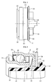
- a ball bearing unit is for clutch release between the engine (drive shaft 59) of a car with manual Transmission and the transmission 52 arranged; she is from the with the service coupled to the clutch pedal (not shown) swinging fork 54 pressed to release, moved on the front cover 53 toward the engine and temporarily blocks the transmission of torque functionally of the engine to the transmission 52 from.
- the clutch pedal Swings the fork 54 counterclockwise and pushes the ball bearing A. by the contact with the side plate axially to the engine.
- This ball bearing unit A for clutch release e.g. those shown in Fig.7 Unit used.
- This ball bearing unit mainly consists of a sleeve 1 made of plastic, a side plate 2 and a ball bearing 3, the is resiliently pressed by the spring means 4 against the side plate 2.
- the Rings of the ball bearing 3 are made of sheet steel by the compression deformation formed and the side plate 2 is integrated with the sleeve 1 made of plastic educated. (see Tokukaihei-270584).
- the bore of the side plate 2 deforms to the oval because of the load of two points of the fork tips. Concretely speaking it deforms by several dozen contrary to the condition without load.
- the integrally formed with the side plate 2 sleeve 1 also deforms under the influence of the bending of the side plate 2. If this strain too is large, the sleeve 1 remains on the front cover during the displacement of the sleeve. 1 Hang and the clutch may be difficult to operate.
- the main object of the invention is to form the sleeve so that it does not deform when the side plate is loaded by the fork tip becomes.
- the self-centering ball bearing unit for clutch release is provided with a ball bearing, which is the point of contact for Touching with the rotating parts of the coupling device comprises a sleeve Plastic, which is located inside the ball bearing, a press-formed Side plate made of sheet steel, which extends from the jacket of the sleeve to the outside, touched radially displaceable with the ball bearing on one axial side and with the release fork on the other side touched and a spring means, the the ball bearing presses elastically against the side plate; it is characterized that the sleeve and the side plate are separated.
- the outer ring is formed of sheet steel and an inwardly aligning Flange identifies and the spring means between the sleeve and the Flange is located, the flange of the outer ring by the pressure force of the spring means pressed against the side plate elastically and the ball bearing is in radially displaceable state held elastically.
- a spring can be placed between the side plate and the sleeve. This may cause the sleeve to tilt relative to the side plate, leaving itself The sleeve can always move along the front cover. Therefore, the Uneven wear and / or metallic adhesion can be avoided.
- the spring means plate spring, wave spring, rubber, etc. may be mentioned become.
- a means that the Avoids twist in between can be provided e.g. such a Avoidance mechanism, on the one hand a recess and on the other hand a projection are provided and engage with each other.
- the bad influence that the bore at the load deformed, thereby excluding that integrated with the sleeve Side plate is formed separately.
- the self-centering ball-bearing unit for clutch release which in the 1 is the same as the ball bearing unit A in Fig.6. She is between the engine (drive shaft 59) of the car with manual transmission and the transmission 52, moves axially on the front cover 53 to the motor side by operating the fork 54, and temporarily locks the Transmission of the rotational force of the engine to the transmission 52 from.
- the ball bearing unit for clutch release consists of a sleeve 10, a side plate 20, as main components a ball bearing 30 and a spring means 40.
- spring means here is a Disc spring shown.
- the sleeve 10 is an approximately cylindrical shaped body (injection molding, etc.).
- the Bore 12 of the sleeve 10 is slidably mounted on the front cover 53.
- a cone-shaped Guide surface 16 is formed, an outwardly projecting stop 18 formed in the middle (closer to the other side), and a side plate is projecting formed on the other side integrated.
- the guide surface 16 has the function to guide the bore of the diaphragm spring 40 when the out of the Ball bearing 30 and the diaphragm spring 40 existing intermediate unit on the Jacket 14 of the sleeve 10 is mounted.
- the stop 18 has the function that the shift from the installed state while gripping with the bore the plate spring 40 is avoided.
- the width of the stop 18 is narrow, one side is an obtuse oblique wall and the other side is a vertical wall or about angled oblique wall, with the hole the diaphragm spring 40 engages.
- One side has the function during assembly to guide the bore of the plate spring 40.
- At the lowest point of the wall of the the other side is a circumferential groove, and the depth this groove is slightly lower than that of the jacket 14.
- the side plate 20 is a press-formed annular body made of sheet steel (see 3) and is integrated around the jacket of the other side of the sleeve 10. With a side surface 22 of the side plate 20, the flange 35 touches the outer ring 34 of the ball bearing 30 slidably in the radial direction. At the other side surface are the contact points with the fork 54 24 each at, for example, 180 ° opposite place arranged.
- the cementing-nitriding treatment for curing the Surfaces performed after the side plate 20 of cold drawn Sheet steel such as e.g. SPCC sheet steel by press molding in specified form was edited. As shown by numeral 26 in Fig.1 or Fig.4, the Peripheral edge of the side plate 20 except the contact point 24, with the Fork 54 touched, bent to the ball bearing side 30. Therefore, the compression and increase the strength of the side plate 20 is provided.
- the ball bearing 30 consists of an inner ring 32 as main components, an outer ring 34, balls 36, a cage 38 and shrouds 31, 39.
- Der Inner ring 32 is formed by pressing from sheet steel, and consists of a essentially in the axial direction extending part and a substantially radially outwardly extending part.
- a raceway 32a is formed on the outer coat of the essential in the axial direction extending part.
- the substantially radially outwardly extending part is as a brim 33 formed, which contacts with the diaphragm spring (55).
- the outer ring 34th is formed by pressing from sheet steel, and consists of a substantially in the axial direction extending part and a substantially radially inwardly extending flange portion 35.
- a raceway 34a is formed inside the bore of the substantially in the axial direction extending part. Between the inner ring 32 and the outer ring 34 are the majority the balls 36 which each contact the raceways 32a, 34a angled. The Balls 36 are by a cage 38 in the circumferential direction with certain Distance kept. On the one hand, a first cover plate 31 and on the other a second cover plate 39 is provided, which closes the gap between the Sheath of the inner ring 32 and the bore of the outer ring 34 seal.
- the first cover plate 31 is an elastic cover plate of non-touching type caused by the impressions of the outer shell is fixed in the one-sided bore of the outer ring 34.
- Their inside Lippe approaches the one-sided shell of the inner ring 32 with the Labyrinth clearance.
- the second cover plate 39 whose section is approximately angled C-shape, is a pressed sheet steel cover plate, which by the impressions of the outer shell in the other side bore of the outer ring 34 is attached; the inside edge approaches the other side Shell of the inner ring 32 with the labyrinth scope.
- first and / or second cover can also be known for bearings cover plates used by the touching type.
- the inner ring 32 is made of sheet steel e.g. by the process of pressing, Heat treatment, grinding of the raceway 32a and the cover disc location produced.
- the raw material of the steel sheet may be the cementable steel sheet and as a heat treatment, cementing heat treatment may be used become.
- cementable steels can nickel-chromium steel (SNC), nickel-chromium-molybdenum steel (SNCM), chrome steel (SCr) and chrome molybdenum steel (SCM).
- SNC nickel-chromium steel
- SNCM nickel-chromium-molybdenum steel
- SCM chrome molybdenum steel
- For nickel-chromium steel (SNC) and nickel-chromium-molybdenum steel (SNCM) of these steels seldom causes overcementing and they are also good material in mechanical property. However, they contain as an alloying element the costly nickel, so that they have problems in terms of cost.
- Inner rings 32 If required for inner rings mechanical property is considered, could be SNC steel or SNCM steel can be over-quality and can not be offset with cost become. In contrast, chromium molybdenum steel (SCM) rarely occurs the over-cementing and he has good deterrent property. Furthermore it is relatively cheaper compared to SNC steel or SNCM steel.
- SCM chromium-molybdenum steel
- the for inner rings the ball bearing unit required mechanical property is sufficiently fulfilled. For these reasons is preferably used as material for Inner rings 32 uses the chromium-molybdenum steel (SCM). In the chromium-molybdenum steels (SCM) there is SCM415 after contained carbon, SCM418, SCM420, SCM421 and SCM822, and the SCM415 thereof is on vorteilhaftesten.
- the ball bearing 30 is between the outer shell 14 of the sleeve 10 and the one-sided side surface 22 of the side plate 20, and by plate spring 40 held elastic as a spring means.
- the plate spring 40 is conical in section produced by pressing, with a majority of the cut out of the Hole is cut out cut out, and with majority of between side by side lying cutouts regularly on the circumference intended. As shown in Fig.1, the plate spring 40 shows because the elastic deformation the cone-angled cylindrical shape, depending on the elastic Deformation of the tongue increases or decreases the bore of the diaphragm spring 40th
- a radial clearance S 1 Between the outer shell 14 of the sleeve 10 and the bore of the inner ring 32 of the ball bearing 30 is a radial clearance S 1 , and between the bore of the flange 35 of the outer ring 34 and the outer shell 14 of the sleeve 10 is radial clearance S 2nd The radial clearance S 2 is smaller than the radial clearance S 1 (S 1 > S 2 ).
- the flange 35 of the outer ring 34 is pressed against the side surface 22 of the side plate 20 elastically; and the ball bearing 30 is elastically held between the outer shell 14 of the sleeve 10 and the side surface 22 of the side plate 20 in the radially displaceable state.
- the ball bearing 30 may be displaced in the radial direction for centering due to the existence of the radial clearance S 1 and S 2 to the sleeve 10 and the side plate 20, and the displacement for centering is limited by the smaller radial clearance S 2 .
- a rotational stop between the Sleeve 10 and the side plate 20 are provided. As shown in Fig. 2, are on the one hand a recess 28 on the side plate 20 and on the other hand, a projection 19 formed on the sleeve 10, and the two interlock. Therefore for example, the sleeve 10 and the side plate 20 can move relatively axially, but not in the circumferential direction.
- FIG 5 shows an embodiment of the embodiment, wherein between the sleeve 10th and the side plate 20, a spring means 42 is clamped.
- the sleeve 10 tend to the side plate 20, and the sleeve 10 may be thereby move along the front cover 53. That is why it is possible to To avoid uneven wear and / or metallic sticking.
- the force from the spring means 40 and the force of Spring means means 42 are approximately equal.
- the ball bearing unit with the seal according to the invention not limited by the above-described embodiment, and may be within the meaning of the invention in various modifications and / or variants be executed.
Abstract
Description
Die Erfindung bezieht sich auf eine selbstzentrierende Kugellager-Einheit zum Kupplungsauslösen, die sich zwischen einem Motor und einem Getriebe befindet und von dem Ersteren zum Letzteren die Kraft überträgt oder sperrt.The invention relates to a self-centering ball bearing unit for clutch release, located between an engine and a transmission and transmits or blocks the force from the former to the latter.
Wie in der Fig.6 schematisch gezeigt ist, ist eine Kugellager-Einheit für Kupplungsauslösen
zwischen dem Motor (Antriebswelle 59) eines Autos mit manuellem
Getriebe und dem Getriebe 52 angeordnet; sie wird von der mit dem Bedienen
des Kupplungspedals (nicht gezeigt) gekoppelt schwingenden Gabel 54
zum Auslösen gedrückt, auf dem Frontdeckel 53 in Richtung zum Motor verschoben
und sperrt funktionsweise zeitweilig die Übertragung des Drehmoments
des Motors zum Getriebe 52 ab. Durch Bedienen des Kupplungspedals
schwingt die Gabel 54 gegen den Uhrzeigersinn und drückt das Kugellager A
durch die Berührung mit der Seitenplatte axial nach dem Motor. Dadurch berührt
der Innenring des Kugellagers A die Membranfeder 55, ferner entfernt sich
durch die Biegungselastizität der Membranfeder 55 die Druckplatte 58, die die
Kupplungsscheibe 56 gegen das Schwungrad 57 drückt, von der Kupplungsscheibe
56. Das Drehmoment der Antriebswelle 59 des Motors wird zeitweilig
vom Getriebe 52 abgesperrt.As shown schematically in FIG. 6, a ball bearing unit is for clutch release
between the engine (drive shaft 59) of a car with manual
Transmission and the
Als Kugellager-Einheit A für Kupplungsauslösen wird z.B. die in der Fig.7 gezeigten
Einheit verwendet. Diese Kugellager-Einheit besteht hauptsächlich aus
einer Muffe 1 aus Kunststoff, einer Seitenplatte 2 und einem Kugellager 3, das
elastisch durch das Federmittel 4 gegen die Seitenplatte 2 gedrückt ist. Die
Ringe des Kugellagers 3 werden aus Stahlblech durch die Pressverformung
gebildet und die Seitenplatte 2 wird mit der Muffe 1 aus Kunststoff integriert
gebildet. (siehe die Offenlegungsschrift Tokukaihei-270584). As the ball bearing unit A for clutch release, e.g. those shown in Fig.7
Unit used. This ball bearing unit mainly consists of
a
Im Fall des obengenannten herkömmlichen selbstzentrierenden Kugellagers
zum Kupplungsauslösen verformt sich die Bohrung der Seitenplatte 2 zum Oval
wegen der Belastung von zwei Punkten der Gabelspitzen. Konkret gesprochen
verformt es sich um mehrere Dutzend entgegen dem Zustand ohne Belastung.
Die mit der Seitenplatte 2 integriert geformte Muffe 1 verformt sich gleichfalls
unter dem Einfluss der Biegung der Seitenplatte 2. Wenn diese Belastung zu
groß ist, bleibt die Muffe 1 am Frontdeckel bei der Verschiebung der Muffe 1
hängen und die Kupplung ist eventuell schwer zu betätigen.In the case of the above conventional self-centering ball bearing
to trigger the coupling, the bore of the
Der Hauptaufgabe der Erfindung besteht darin, die Muffe so auszubilden, dass sie sich nicht verformt, wenn die Seitenplatte von der Gabelspitze belastet wird.The main object of the invention is to form the sleeve so that it does not deform when the side plate is loaded by the fork tip becomes.
Die selbstzentrierbare Kugellager-Einheit für Kupplungsauslösen gemäß der Erfindung ist vorgesehen mit einem Kugellager, das die Berührungsstelle zum Berühren mit der Drehteile der Kupplungsvorrichtung aufweist, einer Muffe aus Kunststoff, die sich innerhalb des Kugellagers befindet, einer pressgeformten Seitenplatte aus Stahlblech, die sich vom Mantel der Muffe nach außen erstreckt, mit dem Kugellager an einer axialen Seite radial verschiebbar berührt und mit der Auslösgabel an der andre Seite berührt und einem Federmittel, das das Kugellager gegen die Seitenplatte elastisch drückt; sie ist dadurch gekennzeichnet, dass die Muffe und die Seitenplatte getrennt sind.The self-centering ball bearing unit for clutch release according to Invention is provided with a ball bearing, which is the point of contact for Touching with the rotating parts of the coupling device comprises a sleeve Plastic, which is located inside the ball bearing, a press-formed Side plate made of sheet steel, which extends from the jacket of the sleeve to the outside, touched radially displaceable with the ball bearing on one axial side and with the release fork on the other side touched and a spring means, the the ball bearing presses elastically against the side plate; it is characterized that the sleeve and the side plate are separated.
Wenn der Innenring des Kugellagers die obengenannte Berührungsstelle aufweist, der Außenring aus Stahlblech gebildet ist und einen nach innen ausrichtenden Flansch ausweist und das Federmittel zwischen der Muffe und dem Flansch liegt, wird der Flansch des Außenrings durch die Druckkraft des Federmittels gegen die Seitenplatte elastisch gedrückt und das Kugellager wird im radial verschiebbaren Zustand elastisch gehalten. If the inner ring of the ball bearing the above-mentioned point of contact has, the outer ring is formed of sheet steel and an inwardly aligning Flange identifies and the spring means between the sleeve and the Flange is located, the flange of the outer ring by the pressure force of the spring means pressed against the side plate elastically and the ball bearing is in radially displaceable state held elastically.
Zwischen der Seitenplatte und der Muffe kann ein Federmittel gelegt werden. Dadurch kann sich die Muffe gegenüber der Seitenplatte neigen, so dass sich die Muffe immer entlang den Frontdeckel verschieben kann. Daher können der ungleiche Verschleiß und / oder das metallische Haften vermieden werden. Als Beispiele des Federmittels können Tellerfeder, Wellenfeder, Gummi usw. genannt werden.A spring can be placed between the side plate and the sleeve. This may cause the sleeve to tilt relative to the side plate, leaving itself The sleeve can always move along the front cover. Therefore, the Uneven wear and / or metallic adhesion can be avoided. When Examples of the spring means plate spring, wave spring, rubber, etc. may be mentioned become.
Zur Vermeidung des Verschleißes wegen des relativen Rutschens zwischen der Seitenplatte und der Muffe kann ein Mittel vorgesehen werden, das die Verdrehung dazwischen vermeidet. Verwendet werden kann z.B. ein solcher Vermeidungsmechanismus, dass einerseits eine Ausnehmung und anderseits ein Vorsprung vorgesehen sind und miteinander greifen.To avoid wear due to relative sliding between the side plate and the sleeve can be provided a means that the Avoids twist in between. It can be used e.g. such a Avoidance mechanism, on the one hand a recess and on the other hand a projection are provided and engage with each other.
Gemäß der Erfindung wird der schlechte Einfluss, dass sich die Bohrung bei der Belastung verformt, dadurch ausgeschlossen, dass die mit der Muffe integrierte Seitenplatte getrennt gebildet ist. Es gibt dadurch Probleme bei herkömmlicher Methode, dass die ungünstige Form wegen des schlechten Fließens des Kunststoffmaterials um die Seitenplatte leicht entstehen kann. Aber dadurch, dass die Muffe und die Seitenplatte getrennt gebildet sind und nur die Muffe separat geformt wird, wird vorteilhafterweise die Genauigkeit eingehalten. Ferner wird die bisher komplizierte Gießform zur integrierten Formung vermieden und die Gießform muss nicht mehr kostspielig sein. Durch die getrennte Formung werden also die Kosten der Gießform billiger und eine Reduzierung der Kosten ist möglich.According to the invention, the bad influence that the bore at the load deformed, thereby excluding that integrated with the sleeve Side plate is formed separately. There are problems with conventional ones Method that the unfavorable shape due to the poor flow of the Plastic material around the side plate can easily arise. But by doing so, that the sleeve and the side plate are formed separately and only the sleeve is formed separately, the accuracy is advantageously maintained. Further the previously complicated mold for integrated molding is avoided and the mold does not have to be expensive anymore. By the separate shaping So are the cost of the mold cheaper and a reduction of the Cost is possible.
Nachfolgend werden Ausführungsbeispiele anhand der Figuren beschrieben. Es zeigt:
- Fig.1
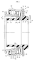
- einen Vertikalschnitt (entsprechend der I-I Linie in der Fig.3) der Kugellager-Einheit für Kupplungsauslösen, der ein Ausführungsbeispiel gemäß der Erfindung darstellt,
- Fig.2
- einen Schnitt entsprechend der II-II Linie in der Fig.1,
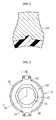
- Fig.3
- eine Seitenansicht der Einheit nach der Fig.1,
- Fig.4
- eine Ansicht von oben der Einheit nach der Fig.1,
- Fig.5
- einen Vertikalschnitt des wichtigen Teils, der ein weiteren Ausführungsbeispiel gemäß der Erfindung darstellt,
- Fig.6
- einen Schnitt, der die Umgebung der Kupplungsvorrichtung des Autos darstellt, und
- Fig.7
- einen Vertikalschnitt des wichtigen Teiles, der die herkömmliche Art darstellt.
- Fig.1
- a vertical section (corresponding to the II line in Figure 3) of the ball bearing unit for clutch release, which represents an embodiment according to the invention,
- Fig.2
- a section corresponding to the II-II line in Figure 1,
- Figure 3
- a side view of the unit according to the Fig.1,
- Figure 4
- a top view of the unit of Figure 1,
- Figure 5
- a vertical section of the important part, which illustrates a further embodiment according to the invention,
- Figure 6
- a section showing the environment of the coupling device of the car, and
- Figure 7
- a vertical section of the important part, which represents the conventional way.
Die selbstzentrierende Kugellager-Einheit zum Kupplungsauslösen, die in der
Fig.1 gezeigt ist, ist gleich wie die Kugellager-Einheit A in der Fig.6. Sie ist zwischen
dem Motor (Antriebswelle 59) des Autos mit manuellem Getriebe und
dem Getriebe 52 angeordnet, verschiebt sich auf dem Frontdeckel 53 axial
nach der Motorseite durch das Betätigen der Gabel 54, und sperrt zeitweilig die
Übertragung der Drehkraft des Motors zum Getriebe 52 ab.The self-centering ball-bearing unit for clutch release, which in the
1 is the same as the ball bearing unit A in Fig.6. She is between
the engine (drive shaft 59) of the car with manual transmission and
the
Die Kugellager-Einheit für Kupplungsauslösen gemäß dieser Ausführungsform
besteht als Hauptkomponenten aus einer Muffe 10, einer Seitenplatte 20,
einem Kugellager 30 und einem Federmittel 40. Als Federmittel ist hier eine
Tellerfeder dargestellt.The ball bearing unit for clutch release according to this embodiment
consists of a
Die Muffe 10 ist ein etwa zylindrisch geformter Körper (Spritzguss etc.). Die
Bohrung 12 der Muffe 10 ist auf dem Frontdeckel 53 verschiebbar aufgesetzt.
An der Kante einer Seite des Mantels 14 der Muffe 10 ist eine kegelförmige
Führungsfläche 16 gebildet, ein nach außen vorspringender Anschlag 18 ist
etwa in der Mitte (näher zu der anderen Seite) gebildet, und eine Seitenplatte ist
vorspringend an der anderen Seite integriert gebildet. Die Führungsfläche 16
hat die Funktion, die Bohrung der Tellerfeder 40 zu führen, wenn die aus dem
Kugellager 30 und der Tellerfeder 40 bestehenden Zwischeneinheit auf dem
Mantel 14 der Muffe 10 montiert wird. Der Anschlag 18 hat die Funktion, dass
die Verschiebung vom eingebauten Zustand unter dem Greifen mit der Bohrung
der Tellerfeder 40 vermieden wird. Die Breite des Anschlags 18 ist schmal,
dessen eine Seite ist eine stumpfwinkelige Schrägwand und die andere Seite
ist eine Senkrechtwand oder etwa spitzwinkelige Schrägwand, die mit der Bohrung
der Tellerfeder 40 greift. Die eine Seite hat die Funktion, bei der Montage
die Bohrung der Tellerfeder 40 zu führen. An der tiefsten Stelle der Wand der
anderen Seite befindet sich eine um die Umfang verlaufende Nut, und die Tiefe
dieser Nut ist etwas tiefer als die des Mantels 14.The
Die Seitenplatte 20 ist ein pressgeformter Ringkörper aus Stahlblech (siehe
Fig.3) und ist um dem Mantel der anderen Seite der Muffe 10 integriert eingesetzt.
Mit einer Seitenfläche 22 der Seitenplatte 20 berührt sich der Flansch 35
des Außenrings 34 des Kugellagers 30 verschiebbar in der Radialrichtung. An
der anderen Seitenfläche sind die mit der Gabel 54 berührenden Berührungsstellen
24 jeweils auf um z.B. 180° entgegengesetzten Stelle angeordnet. In
dieser Ausführungsform ist die Zementier-Nitrier-Behandlung zum Härten der
Oberflächen durchgeführt, nachdem die Seitenplatte 20 aus kaltgezogenem
Stahlblech wie z.B. SPCC-Stahlblech durch Pressformung in festgelegter Form
bearbeitet wurde. Wie mit Ziffer 26 in der Fig.1 oder Fig.4 gezeigt ist, ist der
Umfangsrand der Seitenplatte 20 außer der Berührungsstelle 24, die mit der
Gabel 54 berührt, nach der Kugellagerseite 30 gebogen. Daher ist die Verdichtung
und Erhöhung der Festigkeit der Seitenplatte 20 vorgesehen.The
Das Kugellager 30 besteht als Hauptkomponenten aus einem Innenring 32,
einem Außenring 34, Kugeln 36, einem Käfig 38 und Deckscheiben 31, 39. Der
Innenring 32 ist durch Pressen aus Stahlblech geformt, und besteht aus einem
sich wesentlich in die Axialrichtung erstreckenden Teil und einem sich wesentlich
radial nach außen erstreckenden Teil. Auf dem Außenmantel des sich wesentlich
in die Axialrichtung erstreckenden Teils ist eine Laufbahn 32a gebildet.
Der sich im Wesentlichen radial nach außen erstreckende Teil ist als Krempe
33 ausgebildet, die mit der Membranfeder (55) berührt. Auch der Außenring 34
ist durch Pressen aus Stahlblech geformt, und besteht aus einem sich wesentlich
in die Axialrichtung erstreckenden Teil und einem sich wesentlich radial
nach innen erstreckenden Flanschteil 35. Innen auf der Bohrung des sich wesentlich
in die Axialrichtung erstreckenden Teils ist eine Laufbahn 34a gebildet.
Zwischen dem Innenring 32 und dem Außenring 34 befinden sich die Mehrzahl
der Kugeln 36, die sich jeweils die Laufbahnen 32a, 34a winkelig berühren. Die
Kugeln 36 werden durch einen Käfig 38 in der Umfangsrichtung mit bestimmtem
Abstand gehalten. Einerseits sind eine erste Deckscheibe 31 und anderseits
eine zweite Deckscheibe 39 vorgesehen, die den Spalt zwischen dem
Mantel des Innenrings 32 und der Bohrung des Außenrings 34 dichten.The
In dieser Ausführungsform ist die erste Deckscheibe 31 eine elastische Deckscheibe
vom nicht berührenden Typ, die durch das Eindrücken des Außenmantels
in die einseitigen Bohrung des Außenrings 34 befestigt ist. Deren innenseitige
Lippe nähert sich dem einseitigen Mantel des Innenrings 32 mit dem
Labyrinth-Spielraum. Die zweite Deckscheibe 39, deren Schnitt etwa winkelige
C-Form aufweist, ist eine aus Stahlblech pressgeformte Deckscheibe, die durch
das Eindrücken des Außenmantels in die anderseitigen Bohrung des Außenrings
34 befestigt ist; deren innenseitige Kante nähert sich dem anderseitigen
Mantel des Innenrings 32 mit dem Labyrinth-Spielraum. Als erste und/oder
zweite Deckscheibe können auch die für Wälzlager bekannten Deckscheiben
vom berührenden Typ verwendet werden.In this embodiment, the
Der Innenring 32 wird aus Stahlblech z.B. durch das Verfahren Pressen,
Warmbehandlung, Schleifen der Laufbahn 32a und der Deckscheibenstelle
hergestellt. Als Rohmaterial des Stahlblechs kann das zementierbare Stahlblech
und als Warmbehandlung kann Zementier-Warmbehandlung verwendet
werden. Als zementierbare Stähle können Nickel-Chrom-Stahl (SNC), Nickel-Chrom-Molybdän-Stahl
(SNCM), Chrom-Stahl (SCr) und Chrom-Molybdän-Stahl
(SCM) genannt werden. Bei Nickel-Chrom-Stahl (SNC) und Nickel-Chrom-Molybdän-Stahl
(SNCM) von diesen Stählen entsteht selten die Überzementierung
und sie sind auch in der mechanischen Eigenschaft gutes Material.
Allerdings enthalten sie als Legierungselement das kostspielige Nickel, so
dass sie Probleme bezüglich der Kosten haben. Wenn die für Innenringe erforderliche
mechanischen Eigenschaft in Betracht gezogen wird, könnte SNC-Stahl
oder SNCM-Stahl überqualitativ sein und kann mit Kosten nicht ausgeglichen
werden. Demgegenüber entsteht bei Chrom-Molybdän-Stahl (SCM) selten
die Überzementierung und er hat gute Abschreckungseigenschaft. Außerdem
ist er relative billiger im Vergleich mit SNC-Stahl oder SNCM-Stahl. Die für Innenringe
der Kugellager-Einheit erforderlichen mechanischen Eigenschaft ist
ausreichend erfüllt. Aus diesen Gründen wird vorzugsweise als Material für
Innenringe 32 das Chrom-Molybdän-Stahl (SCM) verwendet. In den Chrom-Molybdän-Stählen
(SCM) gibt es nach enthaltenem Kohlenstoff SCM415,
SCM418, SCM420, SCM421 und SCM822, und das SCM415 davon ist am
vorteilhaftesten.The
Das Kugellager 30 ist zwischen dem Außenmantel 14 der Muffe 10 und der
einseitigen Seitenfläche 22 der Seitenplatte 20 angeordnet, und durch Tellerfeder
40 als Federmittel elastisch gehalten. Die Tellerfeder 40 ist im Schnitt kegelförmig
durch Pressen hergestellt, mit Mehrzahl des Ausschnitts, der von der
Bohrung her ausgeschnitten geformt ist, und mit Mehrzahl der zwischen nebeneinander
liegenden Ausschnitten gebildeten Zunge regelmäßig auf dem Umfang
vorgesehen. Wie in der Fig.1 dargestellt ist, zeigt die Tellerfeder 40 wegen
der elastischen Verformung die kegelwinkelige Zylinderform, je nach der elastischen
Verformung der Zunge vergrößert oder verkleinert die Bohrung der Tellerfeder
40.The
Bei der Montage wird die aus einem eingebauten Kugellager 30 und eine
Tellerfeder 40 bestehende Zwischeneinheit von einer Seite her auf den Außenmantel
14 der Muffe 10 aufgesetzt und eingeschoben, bis der Flansch 35
des Außenrings 34 des Kugellagers 30 mit der Seitenfläche 22 der Seitenplatte
20 berührt und die Zunge (Bohrung) der Tellerfeder 40 mit der anderseitigen
Wand des Anschlags 18 berührt. Im Prozess des Schiebens der obengenannten
Zwischeneinheit kommt die Zunge (Bohrung) der Federmittel 40 zuerst
führend von Führungsstelle 16 der Muffe 10 auf den Außenmantel 14, anschließend
auf den Außenmantel 14 rutschend mit der einseitigen Schrägwand
des Anschlags 18 und ist von der Schrägwand führend in die andere Seite des
Anschlags 18 eingesetzt. Wie beschrieben, wird die Montage bei der Kugellager-Einheit
gemäß dieser Ausführungsform nur dadurch durchgeführt, dass
eine Zwischeneinheit der Kugellager 30 und Tellerfeder 40 auf den Außenmantel
14 der Muffe 10 eingebaut wird (Fig.1).When assembling the built-in
Zwischen dem Außenmantel 14 der Muffe 10 und der Bohrung des Innenrings
32 des Kugellagers 30 befindet sich ein Radialspiel S1, und zwischen der Bohrung
des Flanschs 35 des Außenrings 34 und dem Außenmantel 14 der Muffe
10 befindet sich Radialspiel S2. Das Radialspiel S2 ist kleiner als das Radialspiel
S1 (S1> S2). Durch den Federungsdruck der Tellerfeder 40, die zwischen dem
Anschlag 18 der Muffe 10 und der Bohrung des Flanschs 35 des Außenrings 34
gedrückt liegt, wird der Flansch 35 des Außenrings 34 gegen die Seitenfläche
22 der Seitenplatte 20 elastisch gedrückt; und das Kugellager 30 wird zwischen
dem Außenmantel 14 der Muffe 10 und der Seitenfläche 22 der Seitenplatte 20
im dem in Radialrichtung verschiebbaren Zustand elastisch gehalten. Das Kugellager
30 kann sich auf der Grund der Existenz des Radialspiels S1 und S2 zu
der Muffe 10 und der Seitenplatte 20 in die Radialrichtung zur Zentrierung verschieben,
und die Verschiebung zur Zentrierung wird durch das kleineren Radialspiel
S2 begrenzt. Obwohl die Abweichung zwischen dem Drehzentrum der
Membranfeder (55) und dem Drehzentrum des Kugellagers wegen der beim
Einbau entstandenen Abweichung zwischen der Achse des Frontdeckels (53)
und der Achse der Antriebswelle (59) entstanden ist, kann die Versetzung der
Achsen durch das Verschiebung des Kugellagers 30 zur Zentrierung nach der
Abweichung automatisch verstellt werden. Außerdem wird das Kugellager 30
nach der erforderlichen Verschiebung zur Zentrierung durch die Federungsdruck
des Tellerfeder 40 auf der selben Stelle elastisch gehalten, und versetzt
sich unter Vibrationen und / oder Stoß etc. nicht mehr. Dies bewirkt die sogenannte
Zentriergegenkraft.Between the
In der Ausgestaltung dieser Ausführung ist ein Verdrehanschlag zwischen der
Muffe 10 und der Seitenplatte 20 vorgesehen. Wie in Fig.2 gezeigt ist, sind
einerseits eine Ausnehmung 28 auf der Seitenplatte 20 und anderseits ein Vorsprung
19 auf der Muffe 10 gebildet, und die beiden greifen miteinander. Daher
können sich die Muffe 10 und die Seitenplatte 20 axial relativ bewegen, aber
nicht in Umfangsrichtung.In the embodiment of this embodiment, a rotational stop between the
Fig.5 zeigt eine Ausgestaltung der Ausführung, wobei zwischen der Muffe 10
und der Seitenplatte 20 ein Federmittel 42 geklemmt ist. In diesem Fall kann
sich die Muffe 10 zu der Seitenplatte 20 neigen, und die Muffe 10 kann sich
dadurch entlang den Frontdeckel 53 verschieben. Deshalb ist es möglich, den
ungleichen Verschleiß und / oder das metallische Kleben zu vermeiden. In diesem
Fall ist so eingestellt, dass die Kraft vom Federmittel 40 und die Kraft vom
Federmittel Mittel 42 ungefähr gleich sind.5 shows an embodiment of the embodiment, wherein between the sleeve 10th
and the
Allerdings wird die Kugellager-Einheit mit der Dichtung gemäß der Erfindung von der obengeschriebenen Ausführungsform nicht begrenzt, und kann innerhalb des Sinns der Erfindung in verschiedene Modifikationen und / oder Varianten ausgeführt werden. However, the ball bearing unit with the seal according to the invention not limited by the above-described embodiment, and may be within the meaning of the invention in various modifications and / or variants be executed.
- 1010
- Muffesleeve
- 1212
- Bohrungdrilling
- 1414
- Mantelcoat
- 1616
- Führungsflächeguide surface
- 1818
- Anschlagattack
- 1919
- Vorsprunghead Start
- 2020
- Seitenplatteside plate
- 2222
- Seitenflächeside surface
- 2424
- Berührungsstellecontact point
- 2828
- Ausnehmungrecess
- 3030
- Kugellagerball-bearing
- 3131
- Deckscheibecover disc
- 3232
- Innenringinner ring
- 3333
- Krempebrim
- 3434
- Außenringouter ring
- 3535
- Flanschflange
- 3636
- Kugelnroll
- 3838
- KäfigCage
- 3939
- Deckscheibecover disc
- 4040
- TellerfederBelleville spring
- 5252
- Getriebetransmission
- 5353
- Frontdeckelfront cover
- 5454
- Gabelfork
- 5555
- Membranfederdiaphragm spring
- 5959
- Antriebswelledrive shaft
Claims (4)
dadurch gekennzeichnet, dass die vorgenannte Muffe und die vorgenannte Seitenplatte getrennt sind.A self-centering ball bearing unit for releasing a clutch having a ball bearing having the contact point for contacting with the rotating parts of the coupling device, a plastic sleeve located inside the ball bearing, a press-formed steel sheet side plate extending outwardly from the skirt of the sleeve, contacted with the ball bearing on one axial side radially displaceable and contacted with the release fork on the other side and provided with a spring means which presses the ball bearing against the side plate elastically,
characterized in that the aforesaid sleeve and the aforesaid side plate are separated.
dadurch gekennzeichnet, dass der Innenring des Kugellagers eine Berührungsstelle aufweist, der Außenring mit dem nach innen ausrichtenden Flansch aus Stahlblech gepresst hergestellt ist, und ein Federmittel zwischen der Muffe und dem Flansch des Außenrings vorgesehen ist.Self-centering ball bearing unit according to claim 1,
characterized in that the inner ring of the ball bearing has a contact point, the outer ring is made with the inwardly aligned flange made of sheet steel, and a spring means between the sleeve and the flange of the outer ring is provided.
dadurch gekennzeichnet, dass zwischen der Seitenplatte und der Muffe ein Federmittel geklemmt ist.Self-centering ball bearing unit according to one of claims 1 or 2,
characterized in that a spring means is clamped between the side plate and the sleeve.
Applications Claiming Priority (2)
| Application Number | Priority Date | Filing Date | Title |
|---|---|---|---|
| JP2003405005 | 2003-12-03 | ||
| JP2003405005A JP2005163943A (en) | 2003-12-03 | 2003-12-03 | Clutch release bearing |
Publications (1)
| Publication Number | Publication Date |
|---|---|
| EP1538359A1 true EP1538359A1 (en) | 2005-06-08 |
Family
ID=34463984
Family Applications (1)
| Application Number | Title | Priority Date | Filing Date |
|---|---|---|---|
| EP04028689A Withdrawn EP1538359A1 (en) | 2003-12-03 | 2004-12-03 | Clutch release bearing |
Country Status (2)
| Country | Link |
|---|---|
| EP (1) | EP1538359A1 (en) |
| JP (1) | JP2005163943A (en) |
Cited By (4)
| Publication number | Priority date | Publication date | Assignee | Title |
|---|---|---|---|---|
| DE102005032676A1 (en) * | 2005-07-13 | 2007-01-25 | Schaeffler Kg | Clutch release bearing in contact with a diaphragm spring |
| EP2017491A1 (en) | 2007-07-20 | 2009-01-21 | SNR Roulements | Manufacturing method and mechanically strengthened self-aligning washer |
| WO2015043589A3 (en) * | 2013-09-26 | 2015-11-26 | Schaeffler Technologies AG & Co. KG | Spring arrangement for a hydraulic actuating device |
| RU184971U1 (en) * | 2018-08-30 | 2018-11-15 | Общество с ограниченной ответственностью "Валео Сервис" | CLUTCH SWITCH |
Families Citing this family (3)
| Publication number | Priority date | Publication date | Assignee | Title |
|---|---|---|---|---|
| JP4761208B2 (en) * | 2006-08-03 | 2011-08-31 | 日本精工株式会社 | Bearing device |
| DE102007061589B4 (en) | 2007-01-29 | 2017-06-22 | Nsk Ltd. | Ball bearing and mounting structure |
| JP5045123B2 (en) * | 2007-01-29 | 2012-10-10 | 日本精工株式会社 | Ball bearing and support structure |
Citations (3)
| Publication number | Priority date | Publication date | Assignee | Title |
|---|---|---|---|---|
| DE2457353A1 (en) * | 1974-12-04 | 1976-06-10 | Schaeffler Ohg Industriewerk | Bearing for clutch release mechanism - is mounted with a guide bearing on the shaft which connects clutch with drive |
| FR2465120A1 (en) * | 1979-09-10 | 1981-03-20 | Ferodo Sa | Declutching stop for automobile - uses spring to maintain floating thrust ring and outer bearing race flange against thrust sleeve barrel rib |
| JPH0270584A (en) | 1988-09-05 | 1990-03-09 | Honda Motor Co Ltd | Stand device for motorcycle |
-
2003
- 2003-12-03 JP JP2003405005A patent/JP2005163943A/en not_active Withdrawn
-
2004
- 2004-12-03 EP EP04028689A patent/EP1538359A1/en not_active Withdrawn
Patent Citations (3)
| Publication number | Priority date | Publication date | Assignee | Title |
|---|---|---|---|---|
| DE2457353A1 (en) * | 1974-12-04 | 1976-06-10 | Schaeffler Ohg Industriewerk | Bearing for clutch release mechanism - is mounted with a guide bearing on the shaft which connects clutch with drive |
| FR2465120A1 (en) * | 1979-09-10 | 1981-03-20 | Ferodo Sa | Declutching stop for automobile - uses spring to maintain floating thrust ring and outer bearing race flange against thrust sleeve barrel rib |
| JPH0270584A (en) | 1988-09-05 | 1990-03-09 | Honda Motor Co Ltd | Stand device for motorcycle |
Cited By (7)
| Publication number | Priority date | Publication date | Assignee | Title |
|---|---|---|---|---|
| DE102005032676A1 (en) * | 2005-07-13 | 2007-01-25 | Schaeffler Kg | Clutch release bearing in contact with a diaphragm spring |
| US8286775B2 (en) | 2005-07-13 | 2012-10-16 | Schaeffler Technologies AG & Co. KG | Clutch release bearing in contact with a disk spring |
| DE102005032676B4 (en) * | 2005-07-13 | 2013-01-03 | Schaeffler Technologies AG & Co. KG | Clutch release bearing in contact with a diaphragm spring |
| EP2017491A1 (en) | 2007-07-20 | 2009-01-21 | SNR Roulements | Manufacturing method and mechanically strengthened self-aligning washer |
| FR2919033A1 (en) * | 2007-07-20 | 2009-01-23 | Snr Roulements Sa | MANUFACTURING METHOD AND MECHANICALLY REINFORCED AUTOCENTRING WASHER |
| WO2015043589A3 (en) * | 2013-09-26 | 2015-11-26 | Schaeffler Technologies AG & Co. KG | Spring arrangement for a hydraulic actuating device |
| RU184971U1 (en) * | 2018-08-30 | 2018-11-15 | Общество с ограниченной ответственностью "Валео Сервис" | CLUTCH SWITCH |
Also Published As
| Publication number | Publication date |
|---|---|
| JP2005163943A (en) | 2005-06-23 |
Similar Documents
| Publication | Publication Date | Title |
|---|---|---|
| EP1937991B1 (en) | Slave cylinder with annular piston having axial clearance | |
| DE602004000188T2 (en) | Release device and assembly process | |
| DE102006012016B4 (en) | Clutch release | |
| DE3012019A1 (en) | CLUTCH, ESPECIALLY FOR MOTOR VEHICLES | |
| DE4418284B4 (en) | Torsional vibration double flywheel, especially for motor vehicles | |
| DE112009003458T5 (en) | Clutch bearing, clutch drive device and equipped with these elements motor vehicle | |
| DE4326404B4 (en) | Friction clutch device, in particular for a motor vehicle, and elastic diaphragm spring for such a clutch device | |
| DE60003477T2 (en) | Clutch | |
| EP3030802B1 (en) | Friction coupling having an actuating device | |
| EP1538359A1 (en) | Clutch release bearing | |
| DE202006008940U1 (en) | Clutch release bearing has pressure ring with plastic base body that is manufactured based on polymer filled with micro-glass balls | |
| DE69721193T2 (en) | Kupplungsausrüstvorrichtung | |
| DE2250455A1 (en) | PAIRING A CLUTCH LEVER WITH THE FACE OF A CLUTCH BEARING | |
| DE102017206513A1 (en) | propeller shaft | |
| DE4430249C2 (en) | Clutch cover design with a diaphragm spring | |
| DE2630656A1 (en) | BALL BEARING RELEASES, IN PARTICULAR FOR MOTOR VEHICLE CLUTCHES | |
| DE3427792A1 (en) | SELF-CENTERING EXTRACTOR IN CONNECTION WITH A PLASTIC SLIDING SLEEVE | |
| DE102014212165A1 (en) | Cover arrangement for a friction clutch | |
| DE10196585B3 (en) | Hydrodynamic coupling device, in particular for a motor vehicle | |
| DE60309624T2 (en) | Clutch release bearing with insert for an attack element | |
| DE4129044B4 (en) | Clutch mechanism, in particular for a motor vehicle | |
| DE60300390T2 (en) | Clutch release bearing with attached stop pressure element and manufacturing process | |
| DE102009024163A1 (en) | Power transmission device | |
| DE2630699A1 (en) | BALL BEARING RELEASES, IN PARTICULAR FOR MOTOR VEHICLE CLUTCHES | |
| DE102010022106A1 (en) | Master cylinder for e.g. hydrostatically-operated friction clutch, has counter stop radially overlapping stop and provided at piston rod, and stop ring arranged between stop and counter stop, where ring is made from elastomer or metal |
Legal Events
| Date | Code | Title | Description |
|---|---|---|---|
| PUAI | Public reference made under article 153(3) epc to a published international application that has entered the european phase |
Free format text: ORIGINAL CODE: 0009012 |
|
| AK | Designated contracting states |
Kind code of ref document: A1 Designated state(s): AT BE BG CH CY CZ DE DK EE ES FI FR GB GR HU IE IS IT LI LT LU MC NL PL PT RO SE SI SK TR |
|
| AX | Request for extension of the european patent |
Extension state: AL BA HR LV MK YU |
|
| AKX | Designation fees paid | ||
| STAA | Information on the status of an ep patent application or granted ep patent |
Free format text: STATUS: THE APPLICATION IS DEEMED TO BE WITHDRAWN |
|
| 18D | Application deemed to be withdrawn |
Effective date: 20051209 |
|
| REG | Reference to a national code |
Ref country code: DE Ref legal event code: 8566 |