EP1533515A1 - LUFTEINLASSVORRICHTUNG F R EIN MOTORROLLERARTIGES, ZWEIRûDRIGES KRAFTFAHRZEUG - Google Patents
LUFTEINLASSVORRICHTUNG F R EIN MOTORROLLERARTIGES, ZWEIRûDRIGES KRAFTFAHRZEUG Download PDFInfo
- Publication number
- EP1533515A1 EP1533515A1 EP03736212A EP03736212A EP1533515A1 EP 1533515 A1 EP1533515 A1 EP 1533515A1 EP 03736212 A EP03736212 A EP 03736212A EP 03736212 A EP03736212 A EP 03736212A EP 1533515 A1 EP1533515 A1 EP 1533515A1
- Authority
- EP
- European Patent Office
- Prior art keywords
- air cleaner
- air
- box
- boxes
- scooter
- Prior art date
- Legal status (The legal status is an assumption and is not a legal conclusion. Google has not performed a legal analysis and makes no representation as to the accuracy of the status listed.)
- Granted
Links
Images


Classifications
-
- F—MECHANICAL ENGINEERING; LIGHTING; HEATING; WEAPONS; BLASTING
- F02—COMBUSTION ENGINES; HOT-GAS OR COMBUSTION-PRODUCT ENGINE PLANTS
- F02M—SUPPLYING COMBUSTION ENGINES IN GENERAL WITH COMBUSTIBLE MIXTURES OR CONSTITUENTS THEREOF
- F02M35/00—Combustion-air cleaners, air intakes, intake silencers, or induction systems specially adapted for, or arranged on, internal-combustion engines
- F02M35/10—Air intakes; Induction systems
- F02M35/10006—Air intakes; Induction systems characterised by the position of elements of the air intake system in direction of the air intake flow, i.e. between ambient air inlet and supply to the combustion chamber
- F02M35/10019—Means upstream of the fuel injection system, carburettor or plenum chamber
-
- B—PERFORMING OPERATIONS; TRANSPORTING
- B62—LAND VEHICLES FOR TRAVELLING OTHERWISE THAN ON RAILS
- B62J—CYCLE SADDLES OR SEATS; AUXILIARY DEVICES OR ACCESSORIES SPECIALLY ADAPTED TO CYCLES AND NOT OTHERWISE PROVIDED FOR, e.g. ARTICLE CARRIERS OR CYCLE PROTECTORS
- B62J40/00—Arrangements of air cleaners specially adapted for cycles
- B62J40/10—Arrangements of air cleaners specially adapted for cycles characterised by air duct arrangements
-
- B—PERFORMING OPERATIONS; TRANSPORTING
- B62—LAND VEHICLES FOR TRAVELLING OTHERWISE THAN ON RAILS
- B62K—CYCLES; CYCLE FRAMES; CYCLE STEERING DEVICES; RIDER-OPERATED TERMINAL CONTROLS SPECIALLY ADAPTED FOR CYCLES; CYCLE AXLE SUSPENSIONS; CYCLE SIDECARS, FORECARS, OR THE LIKE
- B62K11/00—Motorcycles, engine-assisted cycles or motor scooters with one or two wheels
-
- F—MECHANICAL ENGINEERING; LIGHTING; HEATING; WEAPONS; BLASTING
- F02—COMBUSTION ENGINES; HOT-GAS OR COMBUSTION-PRODUCT ENGINE PLANTS
- F02M—SUPPLYING COMBUSTION ENGINES IN GENERAL WITH COMBUSTIBLE MIXTURES OR CONSTITUENTS THEREOF
- F02M35/00—Combustion-air cleaners, air intakes, intake silencers, or induction systems specially adapted for, or arranged on, internal-combustion engines
- F02M35/16—Combustion-air cleaners, air intakes, intake silencers, or induction systems specially adapted for, or arranged on, internal-combustion engines characterised by use in vehicles
- F02M35/162—Motorcycles; All-terrain vehicles, e.g. quads, snowmobiles; Small vehicles, e.g. forklifts
-
- B—PERFORMING OPERATIONS; TRANSPORTING
- B62—LAND VEHICLES FOR TRAVELLING OTHERWISE THAN ON RAILS
- B62K—CYCLES; CYCLE FRAMES; CYCLE STEERING DEVICES; RIDER-OPERATED TERMINAL CONTROLS SPECIALLY ADAPTED FOR CYCLES; CYCLE AXLE SUSPENSIONS; CYCLE SIDECARS, FORECARS, OR THE LIKE
- B62K2202/00—Motorised scooters
-
- F—MECHANICAL ENGINEERING; LIGHTING; HEATING; WEAPONS; BLASTING
- F02—COMBUSTION ENGINES; HOT-GAS OR COMBUSTION-PRODUCT ENGINE PLANTS
- F02M—SUPPLYING COMBUSTION ENGINES IN GENERAL WITH COMBUSTIBLE MIXTURES OR CONSTITUENTS THEREOF
- F02M35/00—Combustion-air cleaners, air intakes, intake silencers, or induction systems specially adapted for, or arranged on, internal-combustion engines
- F02M35/02—Air cleaners
Definitions
- the present invention relates to a scooter-type motorcycle intake device in which an air cleaner box is provided on each side of a rear wheel.
- a unit-swinging power train unit having an engine and a rear wheel is attached to a vehicle body frame in such a manner as to swing vertically.
- a front end part of the power train unit is constituted by an engine, and a rear wheel supporting transmission case is attached integrally to a crankcase of the engine.
- a front end part of the engine is supported on the vehicle body frame in such a manner as to swing, and a rear end part of the transmission case is connected to the vehicle body frame via a cushion unit.
- the transmission case is constructed so as to extend longitudinally on a left-hand side of the rear wheel, and power transmission devices for transmitting the drive of the engine to the rear wheel such as a V-belt type automatic transmission and a centrifugal clutch are incorporated therein.
- An intake device that is provided on this type of power train unit adopts a construction in which intake air is induced from an air cleaner box provided above the transmission case into a cylinder through a carburetor above the crankcase.
- the interior of the air cleaner box is partitioned into an upstream-side air compartment and a downstream-side air compartment by an air cleaner element, and a fresh air inlet is opened in the upstream-side air compartment, whereas the carburetor is connected to the downstream-side air compartment via an intake duct.
- the invention was made in view of the situations, and an obj ect thereof is to provide a scooter-type motorcycle intake device which can facilitate the increase in outputs of an engine by increasing the displacement thereof while preventing the unnecessary enlargement of the vehicle body of a scooter-type motorcycle.
- a scooter-type motorcycle intake device characterized in that a first air cleaner box is provided on one side of a rear wheel above a transmission case of a unit-swinging power train unit, whereas a second air cleaner box is provided on the other side of the rear wheel and in that air compartments of the first and second air cleaner boxes are connected to a throttle valve while the air compartments of the air cleaner boxes are made to communicate with each other.
- the second air cleaner box can be provided by making use of a dead space defined on the side of the rear wheel. Consequently, the capacity of the air compartment can be increased by the first and second air cleaner boxes while preventing the enlargement of the vehicle body, whereby there can be provided a scooter-type motorcycle intake device which can facilitate the increase in the output of the engine by increasing the displacement thereof.
- an air cleaner element may be provided in each of the first and second air cleaner boxes, and a fresh air inlet may be formed in an air compartment upstream of the air cleaner element in each of the air cleaner boxes, while an intake duct positioned between the two air cleaner boxes and extending from the throttle valve is connected to respective air compartments downstream of the air cleaner elements.
- the first and second air cleaner boxes are made to have substantially the same construction, and the resistance generatedwhen intake air flows becomes substantially equal over the two air cleaner boxes. Consequently, since intake air flows substantially uniformly in the two air cleaner boxes and a flow path of intake air can be divided into two in order to make effective use of each air cleaner element, the increase in intake resistance can be suppressed to as low a level as possible irrespective of the fact that the two air cleaner elements are provided.
- an air cleaner element is provided in the first air cleaner box, a fresh air inlet is formed in an air compartment upstream of the air cleaner element, and an air compartment downstream of the air cleaner element is made to communicate with a second air cleaner box, the second air cleaner box being formed such that the interior thereof constitutes a closed space.
- the capacity of the air compartment downstream of the air cleaner element in the first air cleaner box is increased by the capacity of the second air cleaner box. Due to this, since a large amount of air in the air cleaner boxes can be supplied to the engine without any resistance, when the opening of the throttle valve is increased, the response of the engine can be improved.
- Figs. 1 to 4 illustrate a first embodiment.
- reference numeral 1 denotes a unit-swinging power train unit equipped with an intake device 2.
- This power train unit includes an engine 3 and a rear wheel 4 which are incorporated therein integrally.
- the power train unit 1 is supported on a vehicle body frame, not shown, of a scooter 7 via a link (not shown) coupled to a coupling boss 6 at an upper end portion of a crankcase 5 of the engine 3 in such a manner as to swing vertically. Note that when used in the following description, left and right indicate transverse directions of the scooter 7 when facing the front of the scooter 7.
- the engine 3 includes the crankcase 5 and a cylinder 8 which protrudes forward and upward from the crankcase 5, and a transmission case 9 which extends in the longitudinal direction is provided on a left-hand side of the rear wheel 4 (refer to Fig. 2).
- the rear wheel 4 is supported by the transmission case 9 and a rear arm 10 which extends rearward from the crankcase 5 on a right-hand side of the rear wheel 4.
- a rear end portion of the transmission case 9 and a rear end portion of the rear arm 10 are connected, respectively, to the vehicle body frame via a cushion unit 11.
- the cylinder 8 extends in such a manner that an axis thereof inclines forward and upward, and an intake device 2, which will be described later on, is connected to an upper surface of a cylinder head 12 of the cylinder 8, while an exhaust pipe 13 is connected to a lower surface of the cylinder head 12.
- the exhaust pipe 13 is provided to extend rearward from the cylinder head 12 in such a manner as to pass by a right-hand side of the crankcase 5 for connection to a muffler 14 on a right-hand side of the rear arm 10.
- a fuel tank 15 is provided in front of the engine 3.
- a radiator 16 is disposed in front of the fuel tank 15.
- an accommodation box 17 is provided above the engine 3.
- This accommodation box 17 is constructed so as to accommodate therein two helmets (not shown), and an upper opening through which the helmets are placed in or taken out of the accommodation box 17 is closed and opened by a seat.
- Two helmet accommodating portions in the accommodation box 17 are denoted by reference numerals 17a, 17b.
- the cylinder 8 includes a cylinder body 18 which protrudes forward and upward from the crankcase 15, the cylinder head 12 fixed to a front end of the cylinder body 18 and a cylinder head cover 19 which is fixed to a front end of the cylinder head 12.
- the intake device 2 includes an intake manifold 21 provided to extend rearward from the cylinder head 12 in such a manner as to pass over the cylinder body 18, an throttle valve 22 connected to a downstream-side end portion of the intake manifold 22 and an air cleaner 23 connected to an intake air inlet of the throttle valve 22.
- An injector 24 for supplying fuel to the engine 3 is mounted on the intake manifold 21.
- the air cleaner 23 is made up of a first air cleaner box 25 positioned at an upper portion of the rear wheel 4 on the left-hand side thereof, a second air cleaner box 26 positioned at an upper portion of the rear wheel 4 on the right-hand side thereof and an intake duct 27 adapted not only to connect the first and second air cleaner boxes 25, 26 with each other but also to connect the two air cleaner boxes to the throttle valve 22.
- the two air cleaner boxes 25, 26 are configured so as to be symmetrical with each other in the transverse direction of the scooter 7.
- the reason why the external shapes of the two air cleaner boxes 25, 26 are different from each other is because the second air cleaner box 26 positioned on the right-hand side of the rear wheel 4 is formed, as shown in Fig. 1, such that a bottom of a rear end portion thereof is elevated in order to avoid the interference with the muffler 14 and a brake caliper 28.
- the first air cleaner box 25 is disposed above the transmission case 9 as is seen with one used on a conventional scooter. As shown in Fig. 2, the air cleaner box 25 is fixed to the transmission case 9 with fixing bolts 29 at two locations at a lower end portion thereof and is supported on the throttle valve 22 via the intake duct 27 at a front end portion thereof.
- the second air cleaner box 26 is disposed in a dead space defined on the right-hand side of the rear wheel 4. To be more specific, the air cleaner box 26 is disposed in the dead space defined above the muffler 14 and the brake caliper 28 and below the accommodation box 17.
- the air cleaner box 26 is fixed to the rear arm 10 with fixing bolts, not shown, at two locations at a lower end portion thereof and is supported on the throttle valve 22 via the intake duct 27 at a front end portion thereof.
- first and second air cleaner boxes 25, 26 are constructed so as to have substantially the same construction, and due to this, here, only the first air cleaner box 25 which is positioned on the left-hand side of the rear wheel 4 will be described in detail with reference to Fig. 4. Note that a direction in which air flows is indicated by arrows in Fig. 4.
- the first and second air cleaner boxes 25, 26 are, as shown in Fig. 4, each made up of a downstream-side box 31 to which the intake duct 27 is attached, an upstream-side box 33 which holds an air cleaner element 32 in cooperation with the downstream-side box 31 therebetween, an air pipe 35 attached to a front wall 34 of the upstream-side box 33 and an air inlet cover 36 which is attached to a front end portion of the upstream-side box 33 to cover an upstream-side end portion of the air pipe 35.
- the downstream-side box 31 is formed into a box-like shape which opens outwardly, and the intake duct 27 is attached to a front end portion of the downstream-side box 31 in such a manner as to pass thereinto.
- This intake duct 27 is made of rubber and formed into a Y-shape (refer to Fig. 3) as viewed from the top so that the angle of the air cleaner boxes 25, 26 can be changed easily when the rear wheel 4 is attached to or detached from the vehicle body.
- the intake duct 27 is disposed between the two air cleaner boxes 25, 26 and is connected to the two air cleaner boxes 25, 26 and the throttle valve 22.
- a drain pipe 37 is provided at a rear end portion of the downstream-side box 31 for discharging water which has entered the interior of the box.
- a cap member, not shown, is put on the drain pipe 37 normally, and the cap member is removed at the time of maintenance.
- the air cleaner element 32 is made up of a frame 38 which is held between the downstream-side box 31 and the upstream-side box 33 and an element main body 39 supported on this frame 38.
- the frame 38 is brought into engagement with the whole area of an open portion of the downstream-side box 31 and is held between the downstream-side box 31 and the upstream-side box 33 when the upstream-side box is attached to the downstream-side box 31.
- a downstream-side air compartment 40 is defined in the interior of the downstream-side box 31 when the air cleaner element 32 is attached to the downstream-side box 31.
- This downstream-side air compartment 40 is made to communicate with a downstream-side air compartment 40 in the second air cleaner box 26 and the air inlet of the throttle valve 22 via the intake duct 27.
- the upstream-side box 33 is formed into a box-like shape which has an opening which confronts the opening portion (the portion where the air cleaner element 32 is mounted) of the downstream-side box 31.
- the air cleaner element 32 is attached to the downstream-side box 31 with attachment screws 41 (refer to Fig. 2) in such a manner as to be held between the upstream-side box 33 and the downstream-side box 31.
- the upstream-side box 33 adopts a construction in which an upstream-side air compartment 42 is defined in a rear part of the upstream-side box 33 which confronts the element main body 39.
- a location of the upstream-side box 33 which is positioned forward of the element main body 39 is made up of a longitudinal plate 43 which confronts the frame 38 of the air cleaner element 32, a front plate 44 which extends outwardly from a front end and upper and lower ends of the longitudinal plate 43, an upper plate 45 (refer to Fig. 3) and a lower plate 46 (refer to Fig. 4).
- a cut-out 47 is formed in the lower plate 46.
- the air pipe 35 attached to the upstream-side box 33 is provided in such a manner as to pass through the front wall 34 to extend longitudinally.
- an opening 35a in a downstream-side end portion of the air pipe 35 inclines in such a manner as to gradually extend outwardly as the pipe extends rearward. Due to this, air which passes through the air pipe 35 into the upstream-side air compartment 42 is scattered over a wide area in the longitudinal direction.
- a fresh air inlet port as set forth in Claim 2 is constituted by this air pipe 35.
- the air inlet cover 36 is formed so as to have a U-shaped cross section so that a front end portion of the upstream-side box 33 is surrounded both on sides and at top and bottom thereof. As shown in Fig. 4, the air inlet cover 36 is attached to a front end portion of the upstream-side box 33 with attachment screw 48. In addition, a gap D is formed, as shown in Fig. 4, between the cover 36 and the front plate 44 of the upstream-side box 33 for inducing outside air into the air cleaner 23. Note that outside air is also induced into the air cleaner 23 from the cut-out 47 formed in the lower plate 46, in addition to the gap D. Thus, muddy water splashed up by a front wheel 49 (refer to Fig. 1) and rain water can be prevented from being picked up into the air cleaner 23 through the construction in which air is taken into the interior of the cover 36 from the relatively narrow gap D and the cut-out 47.
- the first air cleaner box 25 is provided above the transmission case 9 of the unit-swinging power train unit 1 and on the left-hand side of the rear wheel 4
- the second air cleaner box 26 is provided on the right-hand side of the rear wheel 4
- the downstream-side air compartments 40 of the respective air cleaner boxes 25, 26 are made to communicate with each other and are connected to the throttle valve 22.
- the second air cleaner box 26 can be provided by making use of the dead space defined on the side of the rear wheel 4. Consequently, the capacity of the air compartment 40 can be increased by the first and second air cleaner boxes 25, 26 while preventing the enlargement of the vehicle body, thereby making it possible to provide a scooter-type motorcycle intake device which can easily enhance the output of the engine 3 by increasing the displacement of the engine 3.
- the air cleaner element 32 is provided in each of the first air cleaner box 25 and the second air cleaner box 26, the fresh air inlet is formed in the upstream-side air compartment 42 positioned upstream of the air cleaner elements 32 in each of the two air cleaner boxes 25 and 26, and the intake duct 27 extending from the throttle valve 22 is connected to the downstream-side air compartment 40 positioned downstream of the air cleaner element 32 in each of the two air cleaner boxes 25, 26.
- the first and second air cleaner boxes 25, 26 are allowed to have substantially the same construction, and the resistance generated when air flows becomes substantially equal between the two air cleaner boxes 25, 26. Consequently, since a substantially uniform volume of air flows through both the air cleaner boxes 25, 26 and the intake air induction path can be divided into two so that the respective air cleaners 32 can be used effectively, the increase in intake resistance can be suppressed to as low a level as possible, irrespective of the fact that there are provided the two air cleaner elements 32.
- Figs. 5 and 6 illustrate second and third embodiments, respectively. These embodiments are common in many points to the first embodiment with respect to the construction and function. Then, a repeated description of these common points will be omitted by imparting common reference numerals on the drawings, and only different points will be described mainly. In addition, constructions of respective portions of the respective embodiments may be combined variously in view of the object, function and advantage of the invention.
- Fig 5 illustrates a second embodiment.
- a front portion of a downstream-side box 31 of a first air cleaner box 25 positioned on a left-hand side of the rear wheel extends rightward beyond a center line C of the scooter 7 in the transverse direction thereof, and a second air cleaner box 53 according to the embodiment is connected to a distal end portion of the extending portion 52.
- an air cleaner element 32 is provided only in the interior of the first air cleaner box 25.
- An intake duct 27 made up of a rubber pipe is attached to a front part of the extending portion 52 at a central portion thereof as viewed in the transverse direction of the scooter 7, and the air cleaner box is connected to a throttle valve 22, not shown, via the intake duct 27. Note that the same construction as that illustrated in Figs. 1 to 4 is adapted to the other portions of the first air cleaner 25.
- the second air cleaner box 53 is divided transversely so as to be made up of a left half portion 55 and a right half portion 56, and the left half portion 55 is fixed to the extending portion 52 with a fixing screw 54, the left and right half portions 55, 56 being secured to each other so as to define a closed space in the interior thereof.
- the second air cleaner box 53 is formed such that the shape and capacity are smaller than those of the first air cleaner 25.
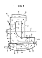
- Fig. 6 illustrates a third embodiment.
- an air cleaner 51 according to this embodiment is constructed so as to have substantially the same construction as that of the second embodiment, a rear end portion of a second air cleaner box 53 of this embodiment is made to communicate with a first air cleaner box 25.
- the second air cleaner box 53 and the first air cleaner box 25 are connected to each other via a communication pipe 61.
- This communication pipe 61 extends in the transverse direction of the scooter 7 and is connected to a downstream-side box 31 of the first air cleaner box 25 and a left half portion 55 of the second air cleaner box 53.
- the capacity of the downstream-side air compartment 40 positioned downstream of the air cleaner element 32 in the first air cleaner box 25 is substantially increased by an amount equal to the capacity of the second air cleaner box 53. Due to this, since a large amount of air within the air cleaner boxes 25, 53 can be supplied to the engine 3 without any resistance, when the opening of the throttle valve 22 is increased, the response of the engine 3 can be improved.
Landscapes
- Engineering & Computer Science (AREA)
- Mechanical Engineering (AREA)
- Chemical & Material Sciences (AREA)
- Combustion & Propulsion (AREA)
- General Engineering & Computer Science (AREA)
- Automatic Cycles, And Cycles In General (AREA)
- Control Of Throttle Valves Provided In The Intake System Or In The Exhaust System (AREA)
- Cooling, Air Intake And Gas Exhaust, And Fuel Tank Arrangements In Propulsion Units (AREA)
Applications Claiming Priority (3)
| Application Number | Priority Date | Filing Date | Title |
|---|---|---|---|
| JP2002175510 | 2002-06-17 | ||
| JP2002175510 | 2002-06-17 | ||
| PCT/JP2003/007584 WO2003106834A1 (ja) | 2002-06-17 | 2003-06-13 | スクータ型自動二輪車の吸気装置 |
Publications (3)
| Publication Number | Publication Date |
|---|---|
| EP1533515A1 true EP1533515A1 (de) | 2005-05-25 |
| EP1533515A4 EP1533515A4 (de) | 2009-06-03 |
| EP1533515B1 EP1533515B1 (de) | 2013-01-09 |
Family
ID=29728040
Family Applications (1)
| Application Number | Title | Priority Date | Filing Date |
|---|---|---|---|
| EP03736212A Expired - Lifetime EP1533515B1 (de) | 2002-06-17 | 2003-06-13 | Lufteinlassvorrichtung für ein motorrollerartiges, zweirädriges kraftfahrzeug |
Country Status (7)
| Country | Link |
|---|---|
| US (1) | US7174981B2 (de) |
| EP (1) | EP1533515B1 (de) |
| JP (1) | JP4165890B2 (de) |
| CN (2) | CN101468707B (de) |
| ES (1) | ES2398746T3 (de) |
| TW (1) | TWI254006B (de) |
| WO (1) | WO2003106834A1 (de) |
Cited By (3)
| Publication number | Priority date | Publication date | Assignee | Title |
|---|---|---|---|---|
| WO2016166688A1 (en) * | 2015-04-15 | 2016-10-20 | Piaggio & C. S.P.A. | Air intake structure for a motorcycle engine |
| EP3321496A1 (de) * | 2016-11-09 | 2018-05-16 | Yamaha Hatsudoki Kabushiki Kaisha | Rollerartiges motorrad |
| EP3321497B1 (de) * | 2016-11-09 | 2020-01-01 | Yamaha Hatsudoki Kabushiki Kaisha | Rollerartiges motorrad |
Families Citing this family (13)
| Publication number | Priority date | Publication date | Assignee | Title |
|---|---|---|---|---|
| JP4341905B2 (ja) * | 2003-09-12 | 2009-10-14 | ヤマハ発動機株式会社 | スクータ型自動二輸車の吸気装置 |
| JP4568569B2 (ja) * | 2004-09-30 | 2010-10-27 | 本田技研工業株式会社 | パーキングブレーキ装置 |
| JP2006142875A (ja) * | 2004-11-16 | 2006-06-08 | Yamaha Motor Co Ltd | 鞍乗型車両 |
| JP5142781B2 (ja) * | 2008-03-27 | 2013-02-13 | 本田技研工業株式会社 | 自動二輪車 |
| JP4996521B2 (ja) * | 2008-03-28 | 2012-08-08 | 本田技研工業株式会社 | 自動二輪車のラジエータリザーブタンク配置構造 |
| JP5922333B2 (ja) * | 2011-03-02 | 2016-05-24 | 本田技研工業株式会社 | 小型車両用エアクリーナ構造 |
| JP5830260B2 (ja) * | 2011-03-24 | 2015-12-09 | 本田技研工業株式会社 | エアクリーナ構造 |
| US8683970B2 (en) | 2011-07-28 | 2014-04-01 | Cnh America Llc | Air intake system for off-road vehicles |
| JP5849346B2 (ja) * | 2012-03-16 | 2016-01-27 | 本田技研工業株式会社 | 鞍乗り型車両における吸気装置 |
| JP5969232B2 (ja) * | 2012-03-22 | 2016-08-17 | 本田技研工業株式会社 | 鞍乗り型車両のラジエータホース配置構造 |
| JP6093176B2 (ja) * | 2012-08-28 | 2017-03-08 | 本田技研工業株式会社 | 鞍乗り型車両の後部構造 |
| DE102014207167A1 (de) | 2014-04-15 | 2015-10-15 | Bayerische Motoren Werke Aktiengesellschaft | Ansaugvorrichtung mit formal integriertem Luftführungsansaugkanal |
| JP6928676B2 (ja) * | 2018-01-17 | 2021-09-01 | 本田技研工業株式会社 | エアクリーナー |
Family Cites Families (28)
| Publication number | Priority date | Publication date | Assignee | Title |
|---|---|---|---|---|
| JPS5217606Y2 (de) | 1973-04-10 | 1977-04-21 | ||
| USD243236S (en) * | 1976-02-27 | 1977-02-01 | W. R. Grace & Co. | Air box for bicycles |
| JPH0692778B2 (ja) * | 1982-06-26 | 1994-11-16 | ヤマハ発動機株式会社 | 自動二輪車の吸気装置 |
| JPS59137216A (ja) * | 1983-01-25 | 1984-08-07 | Yamaha Motor Co Ltd | 自動2輪車 |
| JPS60131317A (ja) | 1983-12-16 | 1985-07-13 | Kawasaki Heavy Ind Ltd | 自動二輪車のv型エンジン用エアクリ−ナ取付構造 |
| JPS61132725A (ja) * | 1984-11-30 | 1986-06-20 | Honda Motor Co Ltd | 自動二輪車用v型2気筒エンジンの吸気装置 |
| US4878555A (en) * | 1984-12-13 | 1989-11-07 | Honad Giken Kogyo Kabushiki Kaisha | Air intake device for a vehicle engine |
| JPS6283798A (ja) | 1985-10-08 | 1987-04-17 | 松下電器産業株式会社 | 連続音声認識装置 |
| JPS6283798U (de) * | 1985-11-18 | 1987-05-28 | ||
| US5433286A (en) * | 1988-09-27 | 1995-07-18 | Honda Giken Kogyo Kabushiki Kaisha | Motorcycle |
| JP2964585B2 (ja) | 1990-08-24 | 1999-10-18 | スズキ株式会社 | 収納ボックス付スクータ型車両 |
| JP2938204B2 (ja) * | 1991-02-22 | 1999-08-23 | ヤマハ発動機株式会社 | 自動二輪車用4サイクルエンジンの吸気装置 |
| CN1042311C (zh) * | 1993-12-27 | 1999-03-03 | 本田技研工业株式会社 | 自动二轮车 |
| JP3368696B2 (ja) * | 1994-10-06 | 2003-01-20 | 川崎重工業株式会社 | 自動二輪車 |
| JPH08114125A (ja) | 1994-10-19 | 1996-05-07 | Yamaha Motor Co Ltd | 自動二輪車の過給装置 |
| JPH08114123A (ja) | 1994-10-14 | 1996-05-07 | Yamaha Motor Co Ltd | 自動二輪車の過給装置 |
| JPH08114122A (ja) | 1994-10-14 | 1996-05-07 | Yamaha Motor Co Ltd | 自動二輪車の過給装置 |
| CN1082140C (zh) * | 1994-10-14 | 2002-04-03 | 雅马哈发动机株式会社 | 两轮摩托车的增压装置 |
| JP3717564B2 (ja) * | 1995-10-05 | 2005-11-16 | ヤマハ発動機株式会社 | エンジンのエアクリーナ |
| JP2000025670A (ja) * | 1998-07-09 | 2000-01-25 | Honda Motor Co Ltd | 自動二輪車 |
| JP3901904B2 (ja) * | 1999-12-17 | 2007-04-04 | 本田技研工業株式会社 | 自動二輪車の吸気チャンバ構造 |
| JP3709971B2 (ja) * | 2000-03-07 | 2005-10-26 | 本田技研工業株式会社 | 車両用vベルト式自動変速機 |
| JP3836665B2 (ja) * | 2000-09-06 | 2006-10-25 | 本田技研工業株式会社 | 自動二輪車 |
| JP3894728B2 (ja) * | 2000-12-28 | 2007-03-22 | 本田技研工業株式会社 | エンジンにおける動弁用タイミング伝動装置 |
| JP3696508B2 (ja) * | 2000-12-28 | 2005-09-21 | 本田技研工業株式会社 | 車両用ラジエータ装置 |
| JP4077173B2 (ja) * | 2001-05-11 | 2008-04-16 | 本田技研工業株式会社 | スクータ型車両 |
| JP2002364467A (ja) * | 2001-06-08 | 2002-12-18 | Yamaha Motor Co Ltd | エンジンの吸気装置 |
| US6601667B2 (en) * | 2001-07-10 | 2003-08-05 | Buell Motorcycle Company | Motorcycle engine cooling system |
-
2003
- 2003-06-03 TW TW092115093A patent/TWI254006B/zh not_active IP Right Cessation
- 2003-06-13 US US10/508,484 patent/US7174981B2/en not_active Expired - Lifetime
- 2003-06-13 WO PCT/JP2003/007584 patent/WO2003106834A1/ja not_active Ceased
- 2003-06-13 ES ES03736212T patent/ES2398746T3/es not_active Expired - Lifetime
- 2003-06-13 EP EP03736212A patent/EP1533515B1/de not_active Expired - Lifetime
- 2003-06-13 CN CN2008101728006A patent/CN101468707B/zh not_active Expired - Lifetime
- 2003-06-13 JP JP2004513625A patent/JP4165890B2/ja not_active Expired - Lifetime
- 2003-06-13 CN CN03810150.5A patent/CN1692220A/zh active Pending
Cited By (5)
| Publication number | Priority date | Publication date | Assignee | Title |
|---|---|---|---|---|
| WO2016166688A1 (en) * | 2015-04-15 | 2016-10-20 | Piaggio & C. S.P.A. | Air intake structure for a motorcycle engine |
| US20180100474A1 (en) * | 2015-04-15 | 2018-04-12 | Piaggio & C. S.P.A | Air intake structure for a motorcycle engine |
| US10364780B2 (en) * | 2015-04-15 | 2019-07-30 | Piaggio & C. S.P.A. | Air intake structure for a motorcycle engine |
| EP3321496A1 (de) * | 2016-11-09 | 2018-05-16 | Yamaha Hatsudoki Kabushiki Kaisha | Rollerartiges motorrad |
| EP3321497B1 (de) * | 2016-11-09 | 2020-01-01 | Yamaha Hatsudoki Kabushiki Kaisha | Rollerartiges motorrad |
Also Published As
| Publication number | Publication date |
|---|---|
| TW200400893A (en) | 2004-01-16 |
| JP4165890B2 (ja) | 2008-10-15 |
| CN101468707A (zh) | 2009-07-01 |
| CN1692220A (zh) | 2005-11-02 |
| TWI254006B (en) | 2006-05-01 |
| US7174981B2 (en) | 2007-02-13 |
| EP1533515A4 (de) | 2009-06-03 |
| ES2398746T3 (es) | 2013-03-21 |
| EP1533515B1 (de) | 2013-01-09 |
| WO2003106834A1 (ja) | 2003-12-24 |
| JPWO2003106834A1 (ja) | 2005-10-13 |
| US20050145427A1 (en) | 2005-07-07 |
| CN101468707B (zh) | 2011-07-20 |
| AU2003241660A1 (en) | 2003-12-31 |
Similar Documents
| Publication | Publication Date | Title |
|---|---|---|
| US7174981B2 (en) | Air intake device for scooter-type two-wheeled motor vehicle | |
| CA2852509C (en) | Air cleaner device for vehicle | |
| JP2010030584A (ja) | 自動二輪車 | |
| US20050066926A1 (en) | Intake air management apparatus for a vehicle, and motorcycle including same | |
| JP2011174428A (ja) | 自動二輪車の吸気温センサ配置構造 | |
| EP2610155A1 (de) | Grätschsitz-Fahrzeug | |
| EP2289787B1 (de) | Grätschsitz-Fahrzeug | |
| US5655497A (en) | Induction system for motorcycle | |
| JP4540762B2 (ja) | 排気2次空気弁を備えた鞍乗型車両 | |
| JP2002213311A (ja) | 車両用エアクリーナ構造 | |
| US8210297B2 (en) | Layout of compact all terrain vehicle for exhaust outlet duct and air inlet duct positioning | |
| US20030213627A1 (en) | Air intake system structure of scooter type vehicle | |
| US8684119B2 (en) | Layout of compact all terrain vehicle for battery positioning | |
| JP3520475B2 (ja) | 自動二輪車の吸気装置 | |
| JP2016049967A (ja) | 小型車両用内燃機関の吸気装置 | |
| JP2008080860A (ja) | 車両用エアクリーナの空気導入構造 | |
| JP2005127218A (ja) | 二次空気供給装置及び自動二輪車 | |
| JP4386304B2 (ja) | スクータ型自動二輪車 | |
| US7665449B2 (en) | V-type engine | |
| JP3965888B2 (ja) | V型エンジンの二次空気供給装置 | |
| JP2007145131A (ja) | 自動二輪車 | |
| JP3158165B2 (ja) | 自動二輪車 | |
| JPH02293286A (ja) | 自動二輪車の吸気装置 | |
| JP3013429B2 (ja) | 自動二輪車のリアーフェンダ装置 | |
| JPWO2022210757A5 (de) |
Legal Events
| Date | Code | Title | Description |
|---|---|---|---|
| PUAI | Public reference made under article 153(3) epc to a published international application that has entered the european phase |
Free format text: ORIGINAL CODE: 0009012 |
|
| 17P | Request for examination filed |
Effective date: 20041216 |
|
| AK | Designated contracting states |
Kind code of ref document: A1 Designated state(s): AT BE BG CH CY CZ DE DK EE ES FI FR GB GR HU IE IT LI LU MC NL PT RO SE SI SK TR |
|
| AX | Request for extension of the european patent |
Extension state: AL LT LV MK |
|
| DAX | Request for extension of the european patent (deleted) | ||
| A4 | Supplementary search report drawn up and despatched |
Effective date: 20090506 |
|
| 17Q | First examination report despatched |
Effective date: 20101019 |
|
| GRAP | Despatch of communication of intention to grant a patent |
Free format text: ORIGINAL CODE: EPIDOSNIGR1 |
|
| GRAS | Grant fee paid |
Free format text: ORIGINAL CODE: EPIDOSNIGR3 |
|
| GRAA | (expected) grant |
Free format text: ORIGINAL CODE: 0009210 |
|
| AK | Designated contracting states |
Kind code of ref document: B1 Designated state(s): AT BE BG CH CY CZ DE DK EE ES FI FR GB GR HU IE IT LI LU MC NL PT RO SE SI SK TR |
|
| REG | Reference to a national code |
Ref country code: GB Ref legal event code: FG4D |
|
| REG | Reference to a national code |
Ref country code: CH Ref legal event code: EP Ref country code: AT Ref legal event code: REF Ref document number: 592897 Country of ref document: AT Kind code of ref document: T Effective date: 20130115 |
|
| REG | Reference to a national code |
Ref country code: IE Ref legal event code: FG4D |
|
| REG | Reference to a national code |
Ref country code: DE Ref legal event code: R096 Ref document number: 60343073 Country of ref document: DE Effective date: 20130307 |
|
| REG | Reference to a national code |
Ref country code: ES Ref legal event code: FG2A Ref document number: 2398746 Country of ref document: ES Kind code of ref document: T3 Effective date: 20130321 |
|
| PG25 | Lapsed in a contracting state [announced via postgrant information from national office to epo] |
Ref country code: SI Free format text: LAPSE BECAUSE OF FAILURE TO SUBMIT A TRANSLATION OF THE DESCRIPTION OR TO PAY THE FEE WITHIN THE PRESCRIBED TIME-LIMIT Effective date: 20130109 |
|
| REG | Reference to a national code |
Ref country code: NL Ref legal event code: VDEP Effective date: 20130109 |
|
| REG | Reference to a national code |
Ref country code: AT Ref legal event code: MK05 Ref document number: 592897 Country of ref document: AT Kind code of ref document: T Effective date: 20130109 |
|
| PG25 | Lapsed in a contracting state [announced via postgrant information from national office to epo] |
Ref country code: BE Free format text: LAPSE BECAUSE OF FAILURE TO SUBMIT A TRANSLATION OF THE DESCRIPTION OR TO PAY THE FEE WITHIN THE PRESCRIBED TIME-LIMIT Effective date: 20130109 Ref country code: AT Free format text: LAPSE BECAUSE OF FAILURE TO SUBMIT A TRANSLATION OF THE DESCRIPTION OR TO PAY THE FEE WITHIN THE PRESCRIBED TIME-LIMIT Effective date: 20130109 Ref country code: BG Free format text: LAPSE BECAUSE OF FAILURE TO SUBMIT A TRANSLATION OF THE DESCRIPTION OR TO PAY THE FEE WITHIN THE PRESCRIBED TIME-LIMIT Effective date: 20130409 Ref country code: SE Free format text: LAPSE BECAUSE OF FAILURE TO SUBMIT A TRANSLATION OF THE DESCRIPTION OR TO PAY THE FEE WITHIN THE PRESCRIBED TIME-LIMIT Effective date: 20130109 Ref country code: CY Free format text: LAPSE BECAUSE OF FAILURE TO SUBMIT A TRANSLATION OF THE DESCRIPTION OR TO PAY THE FEE WITHIN THE PRESCRIBED TIME-LIMIT Effective date: 20130109 |
|
| PG25 | Lapsed in a contracting state [announced via postgrant information from national office to epo] |
Ref country code: NL Free format text: LAPSE BECAUSE OF FAILURE TO SUBMIT A TRANSLATION OF THE DESCRIPTION OR TO PAY THE FEE WITHIN THE PRESCRIBED TIME-LIMIT Effective date: 20130109 Ref country code: GR Free format text: LAPSE BECAUSE OF FAILURE TO SUBMIT A TRANSLATION OF THE DESCRIPTION OR TO PAY THE FEE WITHIN THE PRESCRIBED TIME-LIMIT Effective date: 20130410 Ref country code: PT Free format text: LAPSE BECAUSE OF FAILURE TO SUBMIT A TRANSLATION OF THE DESCRIPTION OR TO PAY THE FEE WITHIN THE PRESCRIBED TIME-LIMIT Effective date: 20130509 Ref country code: FI Free format text: LAPSE BECAUSE OF FAILURE TO SUBMIT A TRANSLATION OF THE DESCRIPTION OR TO PAY THE FEE WITHIN THE PRESCRIBED TIME-LIMIT Effective date: 20130109 |
|
| PG25 | Lapsed in a contracting state [announced via postgrant information from national office to epo] |
Ref country code: DK Free format text: LAPSE BECAUSE OF FAILURE TO SUBMIT A TRANSLATION OF THE DESCRIPTION OR TO PAY THE FEE WITHIN THE PRESCRIBED TIME-LIMIT Effective date: 20130109 Ref country code: SK Free format text: LAPSE BECAUSE OF FAILURE TO SUBMIT A TRANSLATION OF THE DESCRIPTION OR TO PAY THE FEE WITHIN THE PRESCRIBED TIME-LIMIT Effective date: 20130109 Ref country code: CZ Free format text: LAPSE BECAUSE OF FAILURE TO SUBMIT A TRANSLATION OF THE DESCRIPTION OR TO PAY THE FEE WITHIN THE PRESCRIBED TIME-LIMIT Effective date: 20130109 Ref country code: RO Free format text: LAPSE BECAUSE OF FAILURE TO SUBMIT A TRANSLATION OF THE DESCRIPTION OR TO PAY THE FEE WITHIN THE PRESCRIBED TIME-LIMIT Effective date: 20130109 Ref country code: EE Free format text: LAPSE BECAUSE OF FAILURE TO SUBMIT A TRANSLATION OF THE DESCRIPTION OR TO PAY THE FEE WITHIN THE PRESCRIBED TIME-LIMIT Effective date: 20130109 |
|
| PLBE | No opposition filed within time limit |
Free format text: ORIGINAL CODE: 0009261 |
|
| STAA | Information on the status of an ep patent application or granted ep patent |
Free format text: STATUS: NO OPPOSITION FILED WITHIN TIME LIMIT |
|
| 26N | No opposition filed |
Effective date: 20131010 |
|
| REG | Reference to a national code |
Ref country code: DE Ref legal event code: R097 Ref document number: 60343073 Country of ref document: DE Effective date: 20131010 |
|
| PG25 | Lapsed in a contracting state [announced via postgrant information from national office to epo] |
Ref country code: MC Free format text: LAPSE BECAUSE OF FAILURE TO SUBMIT A TRANSLATION OF THE DESCRIPTION OR TO PAY THE FEE WITHIN THE PRESCRIBED TIME-LIMIT Effective date: 20130109 |
|
| REG | Reference to a national code |
Ref country code: CH Ref legal event code: PL |
|
| REG | Reference to a national code |
Ref country code: IE Ref legal event code: MM4A |
|
| PG25 | Lapsed in a contracting state [announced via postgrant information from national office to epo] |
Ref country code: IE Free format text: LAPSE BECAUSE OF NON-PAYMENT OF DUE FEES Effective date: 20130613 Ref country code: CH Free format text: LAPSE BECAUSE OF NON-PAYMENT OF DUE FEES Effective date: 20130630 Ref country code: LI Free format text: LAPSE BECAUSE OF NON-PAYMENT OF DUE FEES Effective date: 20130630 |
|
| PG25 | Lapsed in a contracting state [announced via postgrant information from national office to epo] |
Ref country code: TR Free format text: LAPSE BECAUSE OF FAILURE TO SUBMIT A TRANSLATION OF THE DESCRIPTION OR TO PAY THE FEE WITHIN THE PRESCRIBED TIME-LIMIT Effective date: 20130109 |
|
| PG25 | Lapsed in a contracting state [announced via postgrant information from national office to epo] |
Ref country code: HU Free format text: LAPSE BECAUSE OF FAILURE TO SUBMIT A TRANSLATION OF THE DESCRIPTION OR TO PAY THE FEE WITHIN THE PRESCRIBED TIME-LIMIT; INVALID AB INITIO Effective date: 20030613 Ref country code: LU Free format text: LAPSE BECAUSE OF NON-PAYMENT OF DUE FEES Effective date: 20130613 |
|
| REG | Reference to a national code |
Ref country code: FR Ref legal event code: PLFP Year of fee payment: 14 |
|
| REG | Reference to a national code |
Ref country code: FR Ref legal event code: PLFP Year of fee payment: 15 |
|
| REG | Reference to a national code |
Ref country code: FR Ref legal event code: PLFP Year of fee payment: 16 |
|
| PGFP | Annual fee paid to national office [announced via postgrant information from national office to epo] |
Ref country code: IT Payment date: 20220627 Year of fee payment: 20 Ref country code: GB Payment date: 20220622 Year of fee payment: 20 Ref country code: DE Payment date: 20220620 Year of fee payment: 20 |
|
| PGFP | Annual fee paid to national office [announced via postgrant information from national office to epo] |
Ref country code: FR Payment date: 20220628 Year of fee payment: 20 |
|
| PGFP | Annual fee paid to national office [announced via postgrant information from national office to epo] |
Ref country code: ES Payment date: 20220829 Year of fee payment: 20 |
|
| REG | Reference to a national code |
Ref country code: DE Ref legal event code: R071 Ref document number: 60343073 Country of ref document: DE |
|
| REG | Reference to a national code |
Ref country code: ES Ref legal event code: FD2A Effective date: 20230626 |
|
| REG | Reference to a national code |
Ref country code: GB Ref legal event code: PE20 Expiry date: 20230612 |
|
| P01 | Opt-out of the competence of the unified patent court (upc) registered |
Effective date: 20230527 |
|
| PG25 | Lapsed in a contracting state [announced via postgrant information from national office to epo] |
Ref country code: ES Free format text: LAPSE BECAUSE OF EXPIRATION OF PROTECTION Effective date: 20230614 |
|
| PG25 | Lapsed in a contracting state [announced via postgrant information from national office to epo] |
Ref country code: GB Free format text: LAPSE BECAUSE OF EXPIRATION OF PROTECTION Effective date: 20230612 |