EP1531445A2 - Vorrichtung und Verfahren zur Fahrspursteuerung eines Fahrzeugs - Google Patents
Vorrichtung und Verfahren zur Fahrspursteuerung eines Fahrzeugs Download PDFInfo
- Publication number
- EP1531445A2 EP1531445A2 EP04256894A EP04256894A EP1531445A2 EP 1531445 A2 EP1531445 A2 EP 1531445A2 EP 04256894 A EP04256894 A EP 04256894A EP 04256894 A EP04256894 A EP 04256894A EP 1531445 A2 EP1531445 A2 EP 1531445A2
- Authority
- EP
- European Patent Office
- Prior art keywords
- deviation
- vehicle
- section
- steering angle
- controlled variable
- Prior art date
- Legal status (The legal status is an assumption and is not a legal conclusion. Google has not performed a legal analysis and makes no representation as to the accuracy of the status listed.)
- Granted
Links
- 238000000034 method Methods 0.000 title claims abstract description 21
- 230000003449 preventive effect Effects 0.000 claims description 25
- 238000006073 displacement reaction Methods 0.000 claims description 22
- 239000007788 liquid Substances 0.000 claims description 20
- 230000003247 decreasing effect Effects 0.000 claims description 9
- 239000012530 fluid Substances 0.000 description 13
- 230000001133 acceleration Effects 0.000 description 6
- 230000000694 effects Effects 0.000 description 6
- 230000002265 prevention Effects 0.000 description 5
- 230000005540 biological transmission Effects 0.000 description 2
- 102100033713 Gamma-secretase subunit APH-1B Human genes 0.000 description 1
- 101000733778 Homo sapiens Gamma-secretase subunit APH-1B Proteins 0.000 description 1
- 238000006243 chemical reaction Methods 0.000 description 1
- 238000001514 detection method Methods 0.000 description 1
- 239000000446 fuel Substances 0.000 description 1
- 238000002347 injection Methods 0.000 description 1
- 239000007924 injection Substances 0.000 description 1
- 238000004519 manufacturing process Methods 0.000 description 1
- 230000007935 neutral effect Effects 0.000 description 1
Images


Classifications
-
- B—PERFORMING OPERATIONS; TRANSPORTING
- B62—LAND VEHICLES FOR TRAVELLING OTHERWISE THAN ON RAILS
- B62D—MOTOR VEHICLES; TRAILERS
- B62D15/00—Steering not otherwise provided for
- B62D15/02—Steering position indicators ; Steering position determination; Steering aids
- B62D15/025—Active steering aids, e.g. helping the driver by actively influencing the steering system after environment evaluation
-
- G—PHYSICS
- G08—SIGNALLING
- G08G—TRAFFIC CONTROL SYSTEMS
- G08G1/00—Traffic control systems for road vehicles
- G08G1/16—Anti-collision systems
- G08G1/167—Driving aids for lane monitoring, lane changing, e.g. blind spot detection
-
- B—PERFORMING OPERATIONS; TRANSPORTING
- B60—VEHICLES IN GENERAL
- B60T—VEHICLE BRAKE CONTROL SYSTEMS OR PARTS THEREOF; BRAKE CONTROL SYSTEMS OR PARTS THEREOF, IN GENERAL; ARRANGEMENT OF BRAKING ELEMENTS ON VEHICLES IN GENERAL; PORTABLE DEVICES FOR PREVENTING UNWANTED MOVEMENT OF VEHICLES; VEHICLE MODIFICATIONS TO FACILITATE COOLING OF BRAKES
- B60T2201/00—Particular use of vehicle brake systems; Special systems using also the brakes; Special software modules within the brake system controller
- B60T2201/08—Lane monitoring; Lane Keeping Systems
- B60T2201/082—Lane monitoring; Lane Keeping Systems using alarm actuation
-
- B—PERFORMING OPERATIONS; TRANSPORTING
- B60—VEHICLES IN GENERAL
- B60T—VEHICLE BRAKE CONTROL SYSTEMS OR PARTS THEREOF; BRAKE CONTROL SYSTEMS OR PARTS THEREOF, IN GENERAL; ARRANGEMENT OF BRAKING ELEMENTS ON VEHICLES IN GENERAL; PORTABLE DEVICES FOR PREVENTING UNWANTED MOVEMENT OF VEHICLES; VEHICLE MODIFICATIONS TO FACILITATE COOLING OF BRAKES
- B60T2201/00—Particular use of vehicle brake systems; Special systems using also the brakes; Special software modules within the brake system controller
- B60T2201/08—Lane monitoring; Lane Keeping Systems
- B60T2201/087—Lane monitoring; Lane Keeping Systems using active steering actuation
Definitions
- the present invention relates to lane keep control apparatus and method for an automotive vehicle which are capable of preventing a deviation of the vehicle from a traffic lane on which the vehicle is traveling when the vehicle is about to deviate from the traffic lane during the travel.
- Japanese Patent Application First Publication No. Heisei 11-96497 published on April 9, 1999 exemplifies a first previously proposed lane keep control apparatus.
- the control apparatus determines that the vehicle has a tendency of deviation of the traveled position of the vehicle from a traveling traffic lane and outputs the steering control torque having a magnitude for a vehicle driver to overcome easily in accordance with a lateral deviation of the traveling position with respect to a reference position of the vehicle traveling position through a steering actuator so that the deviation of the vehicle from the traffic lane is prevented.
- Japanese Patent Application First Publication No. 2001-310719 published on November 6, 2001 exemplifies a second previously proposed lane keep control apparatus for the automotive vehicle.
- a yaw moment in a direction to avoid the deviation from the traveling traffic lane is developed according to a difference in a braking force between front and left road wheels so as to prevent the vehicle from being deviated from the traffic lane in a case wherein the control apparatus determines that the vehicle has the tendency to be deviated from the traveling traffic lane.
- an automatic steering causes the vehicle to be prevented from being deviated from the traffic lane. If, during the automatic steering, the driver steers a steering wheel of the vehicle in a direction opposite to that of the automatic steering, it is necessary to generate a steering torque such as to overcome the steering torque caused by the automatic steering. Thus, a steering burden imposed on the driver is increased. In addition, in a case where only the steering torque which can easily overcome the steering torque of the automatic steering is generated, sufficiently speedy steering cannot be carried out and traffic lane deviation preventive performance is consequently weakened. Furthermore, the vehicle driver gives an unpleasant feeling which grasps the steering wheel in a case where a sudden large steering during a traffic lane deviation determination is carried out. A new steering actuator is needed, the number of parts is increased, and a manufacturing cost is increased.
- the traffic lane deviation is prevented from occurring by means of a control of the braking force.
- a yaw moment in a direction to avoid the deviation becomes larger as a manipulated variable of the steering wheel becomes larger irrespective of the fact that the driver can easily steer. Consequently, it becomes difficult for the vehicle to turn round in a direction toward which the driver is steered and a reduction of a vehicle speed becomes large. That is to say, in order to enlarge the effect of the deviation avoidance control, if a gain to calculate the yaw moment from the deviation quantity is set to a large value, the vehicle does not turn round in the way as the vehicle driver has intended so that the vehicle driver deeply gives the unpleasant feeling.
- an object of the present invention to provide improved lane keep control apparatus and method for an automotive vehicle which are capable of performing a steering intervention without giving the vehicle driver an unpleasant feeling during deviation avoidance control.
- a lane keep control apparatus for an automotive vehicle, comprising: a traveling state detecting section that detects a traveling state of the vehicle; a deviation determining section that determines whether the vehicle has a tendency of a deviation from the traveling traffic lane according to the traveling state detected by the traveling state detecting section; a deviation preventive controlling section that executes a deviation avoidance control for the vehicle in a direction to avoid the deviation according to the traveling state detected by the traveling state detecting section; a steering angle detecting section that detects steering angles before and after a start of the deviation avoidance control executed by the deviation preventive controlling section; and a deviation avoidance controlled variable correcting section that corrects a controlled variable of the deviation avoidance control executed by the deviation preventive controlling section on the basis of a deviation between a steering angle before the start of deviation avoidance control and that after the start of deviation avoidance control detected by the steering angle detecting section when the deviation determining section determines that the vehicle has the tendency of the deviation.
- a lane keep control method for an automotive vehicle comprising: detecting a traveling state of the vehicle; determining whether the vehicle has a tendency of a deviation from the traveling traffic lane according to the detected traveling state; executing a deviation avoidance control for the vehicle in a direction to avoid the deviation according to the traveling state; detecting steering angles before and after a start of the deviation avoidance control; and correcting a controlled variable of the deviation avoidance control on the basis of a deviation between a steering angle before the start of deviation avoidance control and that after the start of deviation avoidance control when determining that the vehicle has the tendency of the deviation.
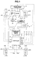
- Fig.1 is a rough configuration view of an automotive vehicle to which a lane keep control apparatus in a first preferred embodiment according to the present invention is applicable.
- Fig. 2 is an operational flowchart representing a traffic lane deviation preventive control process executed by a controller shown in Fig. 1.
- Fig. 3 is an operational flowchart representing a target yaw moment calculation processing in the traffic lane deviation prevention control process shown in Fig. 2.
- Fig. 4 is a calculation map representing a gain K2.
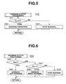
- Fig. 5 is an operational flowchart representing an example of a warning output processing in the traffic lane deviation preventive control process shown in Fig. 2.
- Fig. 6 is an operational flowchart representing another example of the warning output processing in the traffic lane deviation preventive control process shown in Fig. 2.
- Fig. 7 is an operational flowchart representing a target moment correction processing in the traffic lane deviation preventive control process shown in Fig. 2.
- Fig. 8 is an explanatory view for explaining a target yaw moment correction gain Kc.
- Fig. 9 is an operational flowchart representing a braking torque control process in the traffic lane deviation preventive control shown in Fig. 2.
- Figs. 10A, 10B, 10C, and 10D are integrally a timing chart for explaining an operation of the lane keep control apparatus in the first embodiment shown in Fig. 1.
- Fig. 11 is an operational flowchart representing a target yaw moment correction processing in the traffic lane deviation preventive control executed in the lane keep control apparatus in a second preferred embodiment according to the present invention.
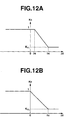
- Figs. 12A and 12B are explanatory views for explaining target yaw moment correction gains in the second embodiment shown in Fig. 11.
- Fig. 1 shows an automotive vehicle to which a lane keep control apparatus in a first preferred embodiment is applicable according to the present invention.
- This vehicle is a rear wheel driven vehicle in which an automatic transmission and a conventional differential gear are mounted.
- a brake device can control a braking force (braking liquid pressure) of each of left and right road wheels between front and rear road wheels, independently of each other.
- reference numeral 1 denotes a brake pedal
- reference numeral 2 denotes a booster
- reference numeral 3 denotes a master cylinder
- reference numeral 4 denotes a reservoir.
- a braking fluid pressure boosted by means of master cylinder 3 in accordance with a depression depth of brake pedal 1 by the vehicle driver is supplied to each wheel cylinder of front road wheels 5FL and 5FR and rear road wheels 5RL and 5RR.
- a braking fluid pressure control circuit 7 is intervened between master cylinder 3 and each wheel cylinder 6FL through 6RR.
- the braking fluid pressure of each wheel cylinder 6FL, 6FR, 6RL, and 6RR can individually be controlled within the braking fluid pressure control circuit 7.
- Braking fluid pressure control circuit 7 is a utilization of the braking fluid pressure control circuit used in, for example, an antiskid control and a traction control.
- the braking fluid pressure of each wheel cylinder 6FL, 6FR, 6RL, and 6RR can solely be controlled (increased or decreased) independently of each other.
- the braking fluid pressure of each wheel cylinder 6FL through 6RR in accordance with a braking fluid pressure command value from a controller 8 as will be described later.
- this vehicle is provided with drive torque controller 12 which controls a driving state of engine 9, a selection gear ratio of an automatic transmission 10, and a throttle opening angle of a throttle valve 11 to control a driving torque to rear road wheels 5RL and 5RR which are driven wheels.
- the driving state control of engine 9, can be carried out, for example, by controlling a fuel injection quantity and an ignition timing and, simultaneously, controlling the opening angle of throttle valve. It is noted that it is possible for driving torque controller 12 to solely control drive torques of rear road wheels 5RL and 5RR which are driven wheels and to control driven wheel torques by referring to the driving torque command value when a command value of the driven torque from controller 8 as described before.
- a CCD camera 13 and a camera controller 14 are disposed in the vehicle as a vehicular surrounding sensor used to detect a position of the vehicle within a traveling traffic lane for determining a traveling traffic lane deviation prevention determination of the vehicle.
- This camera controller 14 detects the traffic lane within which the vehicle is traveling by detecting lane markers such as road block lines from a photographed image located before the vehicular front direction caught (or trapped) by CCD camera 13. Furthermore, yaw angle ⁇ with respect to the traveling traffic lane, a lateral displacement X from a traffic lane center, a curvature ⁇ of the traveling traffic lane, and a traffic lane line width L.
- Controller 8 also receives the signals of yaw angle ⁇ of the vehicle with respect to the traffic lane detected by means of camera controller 14, of lateral displacement X from the center of the traffic lane detected thereby, curvature ⁇ of the traffic lane detected thereby, traffic lane width L detected thereby, and drive torque Tw controlled by means of driving torque controller 12.
- the left direction is a positive direction. That is to say, yaw rate ⁇ , lateral acceleration Yg, and yaw angle ⁇ indicate positive during the left turn and lateral displacement indicates the positive value when the vehicle is deviated toward the left direction from the center of the traveling traffic lane.
- a warning device 24 to produce a warning to the vehicle driver in accordance with an warning signal AL from controller 8 is installed in a front portion of a driver's seat when controller 8 detects the deviation of the vehicle from the traveling traffic lane. Warning device incorporates a speaker to produce a voice or buzzer sound thereinto.
- a traffic lane deviation preventive control processing carried out by controller 8 will be described with reference to a flowchart of Fig. 2. This lane deviation preventive control process is executed by a timer interrupt processing, for example, for each of 10 milliseconds.
- controller 8 calculates a vehicular velocity V from an average value of front left and right road wheel velocities VW FL and VW FR which are non-driven wheels read at step S1.
- V (Vw FL + Vw FR )/2
- controller 8 calculates a future estimated lateral displacement, namely, deviation estimated value XS.
- a future estimated lateral displacement namely, deviation estimated value XS.
- Tt denotes a vehicular head time for calculating a forward gazing distance, and if head time Tt is multiplied with vehicular velocity V, the result is the forward gazing distance.
- controller 8 determines that the vehicle has a traffic lane deviation tendency. It is noted that when the vehicle is deviated toward the left direction, future estimated lateral displacement Xs provides the positive value.
- step S4 controller 8 determines if direction indicator switch 22 is turned on. If direction indicator switch 22 is turned on at step S4, the routine goes to a step S5. At step S5, controller 8 determines if a sign of direction indicator switch WS is made coincident with a sign of deviation estimated value Xs. If both signs are coincident with each other, controller 8 determines that the traffic lane change occurs and the routine goes to a step S6. At step S6, a traffic lane change flag F LC is set to "1" and the routine goes to a step S10.
- step S5 if signs of both are not coincident with each other (No) at step S5, the routine goes to a step S7 determining that no traffic lane change occurs.
- step S7 lane change flag FLC is reset to " 0 " and the routine goes to step S10.
- step S8 controller 8 determines if a predetermined period of time (for example, 4 seconds) has passed. If the predetermined time is not passed at step S8, the routine goes to step S10. If the predetermined period of time has passed (Yes) at step S8, the routine goes to a step S9. At step S9, controller 8 resets traffic lane change flag F LC is reset to " 0 " and the routine goes to step S10. Even if direction indicator switch 22 is released with the operation of the driver during the traffic lane change, an operation of the deviation avoidance control during the traffic lane change can be prevented from occurring.
- a predetermined period of time for example, 4 seconds
- controller 8 determines if an absolute value
- of deviation estimated value Xs is equal to or larger than a warning determination threshold value Xw ( Xc - X M ) calculated by subtracting a margin (constant value) X M from a time at which the warning is operated to a time at which the deviation preventive control is operated from lateral displacement limitation value Xc. If
- controller 8 determines that the vehicle has the tendency of deviation toward the left direction with respect to the traffic lane and the routine goes to a step S14.
- controller 8 sets warning flag Fw to " 1 " and the routine goes to step S17.
- Xs ⁇ 0 at step S13 the routine goes to a step S15.
- controller 8 sets warning flag Fw to " -1 " and the routine goes to step S17.
- step S16 controller 8 determines if absolute value
- Xw - X H denotes a value of the subtraction of a hysteresis value V H to avoid a warning hunting from warning determination threshold value Xw. If
- controller 8 executes a target moment calculation processing shown in Fig. 3 to calculate a target yaw moment Mso required to avoid the deviation state of the vehicle.
- controller 8 executes a warning output processing shown in Fig. 5 so as to carry out a drive processing of the warning device on the basis of warning flag Fw.
- controller 8 executes a target moment correction processing shown in Fig. 7 in which target yaw moment Mso calculated at step S17 is corrected and target yaw moment Ms after the correction is calculated.
- controller 8 executes a braking torque control processing shown in Fig.
- Fig. 3 shows the target moment calculation processing at step S17.
- a deviation determination flag FLD is reset to " 0 " indicating that the vehicle has not the tendency of deviation and the routine goes to a step S33.
- target yaw moment Mso is set to zero and the target moment calculation processing is ended. Then, the routine is ended at a predetermined main program.
- step S34 determines that the deviation warning is carried out and the traffic lane deviation state occurs.
- controller 8 determines if deviation estimated value Xs is equal to or larger than a preset lateral displacement limitation value Xc (in domestic Japan, a traffic lane width of an express way is 3.35 meters and, therefore, for example, preset to about 0.8 meters). If Xs ⁇ Xc at step S34, the routine goes to a step S35 at which F LD is set to " 1 ". Then, the routine goes to a step 538.
- a preset lateral displacement limitation value Xc in domestic Japan, a traffic lane width of an express way is 3.35 meters and, therefore, for example, preset to about 0.8 meters.
- step S36 controller 8 determines whether deviation estimated value Xs is equal to or smaller than a negative value -Xc of the lateral displacement limitation value Xc. If Xs ⁇ - Xc, controller 8 determines that the vehicle has the tendency of the rightward deviation and the routine goes to a step S37. At step S37, deviation determination flag F LD is set to " 1 " and the routine is transferred to step S38. If Xs > -Xc, controller 8 determines that the traffic lane deviation cannot be predicted and the routine goes to step S32.
- controller 8 calculates target yaw moment Mso on the basis of the following equation (3), ends target moment calculating processing, and the routine is returned to the predetermined main program.
- Mso - K1 x K2 x (Xs - Xc)
- K1 denotes a constant determined according to vehicle specifications
- K2 denotes a gain varied in accordance with the vehicular velocity and is calculated by referring to a gain calculation map shown in Fig. 4 on the basis of vehicular velocity V.
- Gain K2 is fixed to a relatively large value K H during the vehicle speed from zero to a predetermined low speed Vs1, gain K2 is decreased in accordance with the increase in vehicle speed V during the vehicle speed V which exceeds predetermined value Vs1 to a predetermined high speed value Vs2, and gain K2 is set so as to fixed to a relatively small threshold value K L when vehicle speed V is in excess of a predetermined value Vs2.
- Fig. 5 shows the warning output processing of step S18.
- step S49 left and right warning signals outputs are halted. Upon stop of the warning, the warning output processing is ended and the routine is returned to the predetermined main program.
- controller 8 determines if target yaw moment Mso calculated at step S17 is not negative or not. If Mso ⁇ 0, the routine goes to a step S52. At step S52, controller 8 calculates a deviation of ⁇ between present steering angle ⁇ and steering angle ⁇ 1 before the deviation avoidance control on the basis of the following equation (4) and the routine goes to a step S57.
- ⁇ ⁇ - ⁇ 1
- step S57 the routine goes to a step S58 since controller 8 determines that the steering wheel is operated in the same direction as the deviation direction and both of deviation estimated value Xs and target yaw moment Mso are naturally increased and determines that target yaw moment correction gain Kc is set to be a value smaller than one (1) with a lower limit value as K CL and target yaw moment Mso is decreased and corrected.
- controller 8 determines if deviation ⁇ is smaller than a predetermined value ⁇ c. If ⁇ ⁇ ⁇ c, the routine goes to a step S59.
- controller 8 calculates target moment correction gain Kc using the following equation (7) and the routine goes to a step S61.
- Kc 1 - ⁇ (1 - K CL )/ ⁇ c ⁇
- K CL denotes a lower limit value of target moment correction gain Kc and 0 ⁇ K CL ⁇ 1.
- step S60 controller 8 sets target moment correction gain Kc to lower limit value K CL on the basis of the following equation (8).
- Kc K CL
- target yaw moment Ms after the correction is calculated by multiplying target yaw moment correction gain Kc calculated at step S56, S59, or S60 with target yaw moment Mso calculated at step S17.
- target moment correction processing is ended, and the routine is returned to the predetermined main program.
- controller 8 sets front left road wheel target liquid pressure P SFL and front right road wheel target liquid pressure P SFR to master cylinder liquid pressure Pm as shown in equation (10) and sets rear left road wheel target liquid pressure P SRL and rear right road wheel target liquid pressure P SRR to a rear road wheel master cylinder pressure Pmr with the front-and-rear distribution calculated from master cylinder pressure Pm taken into consideration. Then, the routine goes to a step S79 as will be described later.
- controller 8 determines whether an absolute value
- controller 8 sets front road wheel side target braking liquid pressure difference to zero as shown in equation (12) and calculates a rear road wheel side target braking liquid pressure difference ⁇ PSR on the basis of the following equation (13) so that the difference is developed only the braking forces between rear left and right road wheels and the routine goes to a step S76.
- step S73 determines whether determination result of step S73 is
- the routine goes to a step S75.
- controller 8 calculates front road wheel side target braking liquid pressure difference ⁇ PSF on the basis of the following equation (14) and calculates rear road wheel side target braking liquid pressure difference ⁇ PSR on the basis of the following equation (15) so as to set the difference between each braking force of road wheels to develop the difference and the routine goes to a step S76.
- ⁇ P SF 2 • K BF • (
- ⁇ P SR 2 • K BR • Ms1/T
- T denotes a tread which is identical to front and rear road wheels
- KBF and KBR denote conversion coefficients to convert the braking force into braking liquid pressure, and is defined as brake specifications.
- ⁇ P SF 2 • K BF •
- /T may be set so as to develop the braking force difference only at the front road wheel side.
- controller 8 determines whether target yaw moment Ms is tried to develop in the negative direction, namely, in the leftward direction. If Ms ⁇ 0, the routine goes to a step S77.
- controller 8 sets front left road wheel target braking pressure PSFL to master cylinder pressure Pm as expressed in the following equation (16), sets front right road wheel braking pressure PSFR to master cylinder pressure Pm plus target braking liquid pressure difference ⁇ PSF as shown in the following equation (17), sets rear left road wheel target braking pressure P SRL to a rear road wheel side master cylinder pressure Pmr as expressed in the following equation (18), and sets rear right road wheel target braking liquid pressure P SRR to rear road wheel side master cylinder pressure Pmr plus rear road wheel side target braking liquid pressure difference ⁇ P SR as expressed in the following equation (19) and the routine goes to a step S79.
- P SFL Pm ... (16)
- P SFR Pm * ⁇ P SF
- SRL Pmr ... (18)
- P SRR Pmr
- step S78 controller 8 sets front left road wheel target braking pressure P SFL to master cylinder pressure Pm plus front road wheel side target braking liquid pressure difference ⁇ P SF as expressed in the following equation (20), sets front right road wheel target braking pressure PSRR to master cylinder pressure Pm as expressed in the following equation (21), sets rear left road wheel target braking pressure PSRL to rear road wheel side master pressure cylinder pressure Pmr plus rear road wheel side target braking liquid pressure difference ⁇ P SR as expressed in the following equation (22), and sets rear right road wheel side target braking pressure P SRR to rear road wheel side master cylinder pressure Pmr as expressed in the following equation (23) and the routine goes to a step S79.
- P SFL Pm + ⁇ P SF
- P SFR Pm
- P SRL Pmr + ⁇ P SR
- P SRR Pmr
- controller 8 determines that the engine output is carried out in accordance with the accelerator manipulation by the vehicle driver and the routine goes to a step S81.
- controller 8 calculates a target drive torque Trq in accordance with the following equation (25) and the routine goes to a step S82.
- Trq f (Acc)
- controller 8 outputs target braking pressures P SFL , P SFR , P SRL , and P SRR to braking fluid control circuit 7 (calculated at steps S72, S77, and S78) and target drive torque Trq calculated at step S80 or step S81 to driving torque controller 12 and the timer interrupt processing is ended to return to the predetermined main program.
- steps S32, S34 through S37 constitute deviation determining means (section)
- the process shown in Fig. 5 corresponds to warning means (a warning section)
- the process shown in Fig. 7 corresponds to the deviation avoidance controlled variable limiting means (section).
- Deviation estimated value Xs is smaller than warning determination threshold value Xw, smaller than Xw - X H .
- the routine goes to step S16 and at step S11 warning flag Fw is reset to " 0 " representing that the warning is not operated.
- deviation determination flag F LD is set to 0 indicating that the vehicle has not tendency of the deviation.
- target braking pressures P SFL through P SRR of respective road wheels 5FL through 5RR are set to master cylinder pressures Pm and Pmr in accordance with the driver's braking operation, respectively, so that the vehicle is traveling in a travel state in accordance with the driver's steering operation.
- step S12 causes step S13 to be passed.
- warning flag Fw is set to " 1 " to inform the driver of the deviation warning.
- deviation determination flag F LD 1, namely, the vehicle has the state in which the deviation tendency is present toward the left direction .
- controller 8 calculates target yaw moment Mso in the direction to avoid the deviation on the basis of the equation (3). Since the driver does not perform the handle operation (steering operation), deviation ⁇ between present steering angle ⁇ and steering angle ⁇ 1 before deviation avoidance control is zero. On the basis of equation (7) at step S59 in Fig. 7, target yaw moment correction gain Kc is calculated as " 1 ". Thus, at step S61, target yaw moment Mso is directly calculated as target yaw moment Ms. To generate this target yaw moment Ms, at step S77 in Fig. 9, right road wheel side target braking fluid pressures P SFR and P SRR are set to be large so that an accurate traveling course correction toward the rightward direction is carried out.
- deviation estimated value Xs provides lateral displacement limitation value Xc. Since the driver does not operate direction indicator switch 22 for a time equal to or longer than a predetermined time, according to the determination at step S4 in Fig. 2, the routine goes to step S8 and step S9 in which traffic lane change flag F LC is reset to " 0 ". Since
- Xc,
- ⁇ Xw is established and at step S14 warning flag F LD is set to " 1 " indicating that the warning is activated. In addition, since Xs Xc, according to the determination at step S34 in Fig.
- step S35 the routine is transferred to step S35 and deviation determination flag F LD is set to " 1 " indicating that the vehicle has the tendency to be deviated toward the leftward direction.
- step S38 target yaw moment Mso in the deviation avoidance direction is calculated as " 0 " under the equation (3).
- step S55 of Fig. 7 steering angle ⁇ at time point t1 is set as steering angle ⁇ 1 before deviation avoidance control.
- Fig. 10 C In a state in which steering angle ⁇ maintained constant, the traffic lane change is continued.
- Xs ⁇ Xc.
- target moment correction gain Kc is calculated to be 1 on the basis of equation (7).
- target yaw moment Mso calculated at step S38 is calculated directly as target yaw moment Ms.
- right road wheel side target braking fluid pressures P SFR and P SRR at step S77 of Fig. 9 are set to be large so that the deviation avoidance control in the rightward direction is carried out.
- the driver further carries out the steering operation so that steering angle ⁇ is increased more.
- ⁇ ⁇ ⁇ 1 If ⁇ ⁇ ⁇ 1 + ⁇ c, according to the determination at step S57 in Fig. 7, the routine goes to step S59 via step S58.
- target moment correction gain Kc in accordance with deviation ⁇ is calculated to be smaller than 1.
- target yaw moment Ms after the correction at step S61 is smaller than target yaw moment Mso.
- controlled variable of the deviation avoidance control toward the right direction which is the deviation avoidance direction is limited.
- target moment correction processing shown in Fig. 7 is not carried out.
- right road wheel side braking fluid pressures P SFR and P SRR are set to be large to develop target yaw moment Mso calculated at step S38 and the deviation avoidance control toward the rightward direction is carried out.
- target yaw moment Mso is calculated in such a way that its absolute value becomes large in accordance with the increase in deviation estimated value Xs increased along with the driver's steering operation of the driver. Therefore, as denoted by the broken line shown in Fig. 10C, a large steering operation more than necessity is carried out in order to reach to a traveling trajectory of the driver's target.
- step S20 shown in Fig. 2 in a case where such a yaw moment that the control of the braking torque for front and rear left and right road wheels is carried out to avoid the deviation is developed, the braking torque of either left or right road wheels becomes larger. Consequently, the traveling speed of the vehicle becomes reduced largely and the driver is given and unpleasant feeling.
- target yaw moment correction processing shown in Fig. 7 is carried out.
- the controlled variable of deviation avoidance control can be limited.
- the unpleasant feeling to the driver can be reduced.
- the deviation avoidance control in a case where the deviation avoidance control is started in which deviation estimated value Xs is equal to or larger than lateral displacement limit value Xc and the driver furthermore steers the steering wheel in the deviation direction in a state in which the deviation speed toward an outside of the traveling traffic lane due to the effect of the deviation avoidance control, it is difficult to think that the driver unconsciously operates the steering wheel but the intention of the driver can assuredly be determined to carry out the steering operation.
- the limitation of the controlled variable of the deviation avoidance control causes an effective reduction in the driver's unpleasant feeling.
- the steering angle is detected to have the increase tendency from a time at which the deviation avoidance control start, it is more clearly understandable that the driver tries to operate the vehicle in the deviation direction of the traffic lane.
- the correction processing such as to limit the target yaw moment is carried out so that the driver can easily intervene the steering.
- the controlled variable of the deviation avoidance control is not limited and a safe deviation avoidance control can be carried out without unwilling limitation on the controlled variable.
- the steering angles before and after the start of the deviation avoidance control are detected and the controlled variable of the deviation avoidance control on the basis of the deviation between the steering angle before the deviation avoidance control and the steering angle after the deviation avoidance control.
- the controlled variable of the deviation avoidance control can be limited only in a case where the vehicle driver assuredly intervenes the steering.
- the deviation avoidance control is limited in accordance with the steering intervention on the basis of the deviation of the steering angle. Hence, a speedily reduction in the unpleasant feeling of the driver along with the steering wheel manipulated variable.
- the controlled variable of the deviation avoidance control is limited.
- the controlled variable of the deviation avoidance control for the driver to intervene the steering in the direction that the driver has a strong unpleasant feeling can be limited.
- a safety deviation avoidance can be carried out without reduction in the effect of the deviation avoidance control.
- target yaw moment correction gain Kc is calculated so as to become linearly decreased from 1 to lower limit value K CL when deviation ⁇ of the steering angle is increased from 0 to predetermined value ⁇ C using equation (7).
- the present invention is not limited to this.
- Such a function as to monotonously decrease together with the increase in the deviation of steering angle ⁇ may be applied to this correction gain Kc.
- lower limit value K CL may be zero.
- target yaw moment due to the deviation avoidance control can be limited to zero. Hence, for the driver, the steering becomes easier to be operated.
- the correction processing of the deviation avoidance control is carried out using target moment correction gain Kc shown in Fig. 8.
- the present invention is not limited to this. If deviation ⁇ of the steering angle is equal to or larger than the predetermined value, such a correction processing that the controlled variable is gradually limited along with the elapse of time may be carried out.
- controller determines the turning state of the vehicle, calculates an offset steering angle as an ideal steering angle, and limits the controlled variable of the deviation avoidance control on the basis of the deviation between the offset steering angle and the steering angle before and after the deviation avoidance control.
- Fig. 11 shows an operational flowchart representing a target moment correction processing executed by controller 8 in the second embodiment.
- steps S91 through S97 to calculate offset steering angle ⁇ s which accords with the steering state when determining the turning state of the vehicle are added
- the process at step S57 is replaced with a step S98 in which controller 8 determines whether the deviation ⁇ of the steering wheel is smaller than offset steering angle ⁇ s
- the process at step S58 is replaced with a step S99 in which deviation ⁇ is smaller than a sum ( ⁇ c + ⁇ s) of predetermined value ⁇ c and offset steering angle ⁇ s
- the process at step S59 is replaced with a step S100 in which target moment correction gain Kc is calculated on the basis of offset steering angle ⁇ s and deviation ⁇ .
- the same processing as shown in Fig, 7 is executed.
- the corresponding portions in Fig. 11 to Fig. 7 are designated with the same signs and the detailed description will be omitted
- controller 8 determines that the vehicle is steadily turned state and the routine goes to a step S93.
- controller 8 sets a turning determination flag Flag to " 1 " indicating that the vehicle is being turned and the routine goes to step S95 as will be described later.
- controller 8 determines that the vehicle is traveling on the straight road and the routine goes to a step S94.
- step S94 turning determination flag Flag is reset to " 0 " and the routine goes to step S95.
- controller 8 determines if turning determination flag is set to " 1 " and the vehicle has the tendency of deviating toward an outside of the curve (curved road).
- controller 8 calculates offset steering angle ⁇ s used in the calculation of target yaw moment correction gain Kc.
- This offset steering angle ⁇ s may be calculated to derive the ideal steering angle prescribed in accordance with the curvature of the traffic lane in travel and is calculated on the basis of the vehicle speed V, curvature ⁇ , wheel base 1, and a stability factor A on the basis of the following equation (26).
- ⁇ s (1 + AV 2 ) x 1 x
- steps S51 through S55 deviation ⁇ of steering angle before and after the deviation avoidance control is calculated.
- step S98 controller 20 determines whether deviation ⁇ is smaller than offset steering angle ⁇ s calculated at step S96 or step S97. If ⁇ ⁇ ⁇ S, the routine goes to step S56.
- step S56 controller 8 sets the target moment correction gain Kc to " 1 " and the routine goes to step S61.
- step S99 controller 8 determines whether deviation ⁇ is smaller than a sum of predetermined value ⁇ C and offset steering angle ⁇ s ( ⁇ c + ⁇ s). If ⁇ ⁇ ⁇ c + ⁇ s, the routine goes to a step S100. On the basis of the following equation (28), controller 8 calculates target moment correction gain Kc and the routine goes to a step S61.
- Kc 1 - ⁇ (1 - K CL )/( ⁇ c - ⁇ s) ⁇ ( ⁇ - ⁇ s)
- step S60 the routine goes to a step S60 at which controller 8 sets target moment correction gain Kc to lower limit value K CL .
- steps S92 through S97 correspond to ideal steering angle calculating means.
- the deviation tendency is present on the outer side of the curved road.
- the force to operate the steering wheel by the driver is loosened and without consideration of the ideal steering
- the correction processing of target yaw moment is executed.
- the driver is determined to operate the steering wheel in the same direction as the deviation direction and the controlled variable of the deviation avoidance control is limited.
- the vehicle becomes easy to be deviated from the traveling traffic lane and the effect of the deviation avoidance control might largely be damaged.
- target moment correction processing shown in Fig. 11 is executed so that the vehicle is in the deviation state toward the outer side of the turning.
- controller 8 calculates the ideal steering angle required to turn the curve during the traveling in accordance with the curvature of the traffic lane and determines that the steering operation to the deviation direction is not carried out by the driver if the steering angle is varied in the deviation direction more than the ideal steering angle and controller 8 does not limit the target yaw moment.
- controller 8 determines that the driver intentionally operates the steering wheel toward the deviation direction, the target yaw moment is limited. Hence, the steering intervention without unpleasant feeling given to the driver can be carried out.
- step S97 offset steering angle ⁇ s is set to " 0 ".
- target moment correction gain Kc is set to a value smaller than 1 and the target yaw moment is limited.
- controller 8 calculates the ideal steering angle required to turn the curve during the traveling in accordance with the curvature of the traveling traffic lane of the vehicle and does not limit the controlled variable of the deviation avoidance control until the deviation of the steering angle before and after the deviation avoidance control has reached to the same magnitude as the ideal steering angle.
- the controlled variable of the deviation avoidance control is limited only if the vehicle tends to be deviated toward outside of the turning. Hence, the controlled variable of deviation avoidance control can immediately be limited in the case where the vehicle has the tendency of deviating toward the inner side of the turning. The unpleasant feeling of the vehicle driver during the steering intervention can extremely be suppressed.
- a required controlled variable to make a travel in accordance with the curvature may be calculated and the controlled variable of the deviation avoidance control may be limited in accordance with the deviation between the required controlled variable calculated and the controlled variable of the deviation avoidance control.
- the travel control in accordance with the curvature is carried out so that the behavior of the vehicle can be difficult to be disordered.
- deviation avoidance controlled variable may be limited in accordance with the required controlled variable calculated on the basis of the traveling state of the vehicle and curvature ⁇ of the traffic lane.
- stability of the vehicular motion and easiness in steering intervention of the driver is compatible as high as possible.
- the target moment correction gain may be calculated in accordance with only the deviation of the steering angle before and after the deviation avoidance control.
- the target moment correction gain may be calculated in accordance with one of the road block lines which is toward the deviation side.
- the vehicular surrounding sensor detects the road block line of the traveling traffic lane and determines a protrusion inhibit block line (solid line) for the vehicle to be inhibited from being protruded.
- the target moment correction gain such as to limit the controlled variable of the deviation avoidance control immediately is calculated.
- the target moment correction gain is set to " 1 " assuming that the deviation avoidance control is not limited.
- the warning in a case where the vehicle has the tendency of deviation, irrespective of the presence or absence of the limitation on the deviation avoidance controlled variable, the warning is always produced at a constant volume.
- the volume produced from the warning device may be set to be minor.
- the braking torque control controls the vehicular yaw moment by means of the braking torque control so as to prevent the traffic lane deviation.
- the steering control may prevent the traffic lane deviation.
- yaw moment Ms in the deviation avoidance direction is developed on the vehicle only by controlling braking pressure P SFL through P SRR of respective road wheels 5FL, 5FR, 5RL, and 5RR.
- the present invention is not limited to this.
- braking force control unit which is enabled to control driving forces of respective road wheels 5FL through 5RR is mounted in the vehicle
- yaw moment Ms in the deviation avoidance direction by controlling the braking pressures and driving forces of respective road wheels 5FL through 5RR may be developed.
- the present invention is applicable to rear road wheel drive vehicle.
- the present invention is applicable to a front road wheel drive vehicle.
- vehicular velocity V of the vehicle may be calculated from an average value of left and right road wheel velocities V WFL and V WRR which are non-driven wheels from among respective road wheel velocities V WFL through V WRR .
Applications Claiming Priority (2)
| Application Number | Priority Date | Filing Date | Title |
|---|---|---|---|
| JP2003384196A JP3982483B2 (ja) | 2003-11-13 | 2003-11-13 | 車線逸脱防止装置 |
| JP2003384196 | 2003-11-13 |
Publications (3)
| Publication Number | Publication Date |
|---|---|
| EP1531445A2 true EP1531445A2 (de) | 2005-05-18 |
| EP1531445A3 EP1531445A3 (de) | 2006-04-19 |
| EP1531445B1 EP1531445B1 (de) | 2008-07-16 |
Family
ID=34431479
Family Applications (1)
| Application Number | Title | Priority Date | Filing Date |
|---|---|---|---|
| EP04256894A Active EP1531445B1 (de) | 2003-11-13 | 2004-11-08 | Vorrichtung und Verfahren zur Fahrspursteuerung eines Fahrzeugs |
Country Status (5)
| Country | Link |
|---|---|
| US (1) | US7117076B2 (de) |
| EP (1) | EP1531445B1 (de) |
| JP (1) | JP3982483B2 (de) |
| CN (1) | CN100387476C (de) |
| DE (1) | DE602004015045D1 (de) |
Cited By (2)
| Publication number | Priority date | Publication date | Assignee | Title |
|---|---|---|---|---|
| EP2487085A3 (de) * | 2011-02-11 | 2014-08-13 | Scania CV AB | Spurwechselwarnsystem und Verfahren für ein Spurwechselwarnsystem |
| EP2987703A3 (de) * | 2008-03-04 | 2016-03-23 | Nissan Motor Co., Ltd. | Spurhaltungsunterstützungsvorrichtung und spurhaltungsunterstützungsverfahren |
Families Citing this family (60)
| Publication number | Priority date | Publication date | Assignee | Title |
|---|---|---|---|---|
| US7212901B2 (en) * | 2003-10-29 | 2007-05-01 | Nissan Motor Co., Ltd. | Lane departure prevention apparatus |
| JP4148179B2 (ja) * | 2004-04-23 | 2008-09-10 | 日産自動車株式会社 | 車線維持支援装置 |
| JP4349210B2 (ja) * | 2004-06-02 | 2009-10-21 | トヨタ自動車株式会社 | 運転支援装置 |
| JP4867313B2 (ja) * | 2004-12-27 | 2012-02-01 | 日産自動車株式会社 | 車線逸脱防止装置 |
| JP2006264624A (ja) * | 2005-03-25 | 2006-10-05 | Daimler Chrysler Ag | 車線維持支援装置 |
| JP4124213B2 (ja) * | 2005-05-27 | 2008-07-23 | トヨタ自動車株式会社 | 車両逸脱防止装置 |
| AU2006281802A1 (en) | 2005-08-18 | 2007-02-22 | Sauer-Danfoss Aps | A method of calibrating and steering a vehicle provided with a positioning system |
| CN101126640B (zh) * | 2006-08-16 | 2010-05-26 | 鸿富锦精密工业(深圳)有限公司 | 汽车及其安全系统 |
| US20080168941A1 (en) * | 2007-01-11 | 2008-07-17 | Haynes Paul A | Apparatus and method for guiding driver of a motor vehicle to enter a correct lane after a turn at an intersection |
| DE102007022184A1 (de) * | 2007-05-11 | 2008-11-13 | Robert Bosch Gmbh | Fahrerassistenzvorrichtung und Verfahren für dessen Steuerung |
| JP4748122B2 (ja) * | 2007-06-28 | 2011-08-17 | 日産自動車株式会社 | 車線逸脱防止装置 |
| JP5380860B2 (ja) * | 2008-03-04 | 2014-01-08 | 日産自動車株式会社 | 車線維持支援装置及び車線維持支援方法 |
| JP5359516B2 (ja) * | 2008-07-29 | 2013-12-04 | 日産自動車株式会社 | 車両運転支援装置及び車両運転支援方法 |
| JP5282889B2 (ja) * | 2009-01-13 | 2013-09-04 | トヨタ自動車株式会社 | 車両の操舵制御装置 |
| JP5297965B2 (ja) * | 2009-09-30 | 2013-09-25 | 日立オートモティブシステムズ株式会社 | 走行支援装置 |
| JP5325765B2 (ja) | 2009-12-28 | 2013-10-23 | 日立オートモティブシステムズ株式会社 | 路肩検出装置及び路肩検出装置を用いた車両 |
| JP5510037B2 (ja) * | 2010-04-28 | 2014-06-04 | 日産自動車株式会社 | 狭路走行支援装置、狭路走行支援方法 |
| US8717192B2 (en) * | 2010-10-08 | 2014-05-06 | Navteq B.V. | Method and system for using intersecting electronic horizons |
| US8467956B2 (en) | 2010-10-18 | 2013-06-18 | Telenav, Inc. | Navigation system with lane-level mechanism and method of operation thereof |
| US8818704B2 (en) | 2010-10-18 | 2014-08-26 | Telenav, Inc. | Navigation system with road object detection mechanism and method of operation thereof |
| WO2012068331A1 (en) | 2010-11-19 | 2012-05-24 | Magna Electronics Inc. | Lane keeping system and lane centering system |
| US8977419B2 (en) * | 2010-12-23 | 2015-03-10 | GM Global Technology Operations LLC | Driving-based lane offset control for lane centering |
| DE102011121117B4 (de) * | 2011-12-14 | 2018-02-01 | Audi Ag | Verfahren zur Seitenwindstabilisierung eines Kraftfahrzeugs sowie Kraftfahrzeug umfassend Vorder- und Hinterräder und eine Einrichtung zur Erfassung einer Seitenablage |
| CN102514490A (zh) * | 2012-01-05 | 2012-06-27 | 安徽华菱汽车有限公司 | 车道偏离警示控制装置 |
| SE536571C2 (sv) * | 2012-06-12 | 2014-02-25 | En metod och ett system för körfältshjälp för ett fordon | |
| DE112012006679B4 (de) * | 2012-07-09 | 2017-07-06 | Toyota Jidosha Kabushiki Kaisha | Fahrzeuglenksteuerungsvorrichtung |
| KR101997429B1 (ko) * | 2012-10-19 | 2019-07-08 | 현대모비스 주식회사 | 차량의 차선 유지 제어 방법 및 이를 구현하는 차선 유지 제어 장치 |
| CN102951159B (zh) * | 2012-11-07 | 2016-06-15 | 浙江吉利汽车研究院有限公司杭州分公司 | 车道偏离预警系统 |
| US8880273B1 (en) | 2013-01-16 | 2014-11-04 | Google Inc. | System and method for determining position and distance of objects using road fiducials |
| US20160193999A1 (en) * | 2013-07-19 | 2016-07-07 | Honda Motor Co., Ltd. | Vehicle travel safety device, vehicle travel safety method, and vehicle travel safety program |
| JP6327701B2 (ja) * | 2014-03-28 | 2018-05-23 | 株式会社Subaru | 車両の車線逸脱防止制御装置 |
| JP5991340B2 (ja) * | 2014-04-28 | 2016-09-14 | トヨタ自動車株式会社 | 運転支援装置 |
| JP6086106B2 (ja) * | 2014-10-16 | 2017-03-01 | トヨタ自動車株式会社 | 運転支援装置 |
| US10713506B2 (en) | 2014-12-18 | 2020-07-14 | Magna Electronics Inc. | Vehicle vision system with 3D registration for distance estimation |
| US9946940B2 (en) | 2014-12-18 | 2018-04-17 | Magna Electronics Inc. | Vehicle vision system with adaptive lane marker detection |
| US10449899B2 (en) | 2015-05-08 | 2019-10-22 | Magna Electronics Inc. | Vehicle vision system with road line sensing algorithm and lane departure warning |
| JP6109894B2 (ja) * | 2015-08-27 | 2017-04-05 | 富士重工業株式会社 | 車両制御装置および車両制御方法 |
| CN107024929B (zh) * | 2016-02-02 | 2020-09-22 | 香港中文大学深圳研究院 | 一种基于道路信息的车辆控制方法及装置 |
| US10055651B2 (en) | 2016-03-08 | 2018-08-21 | Magna Electronics Inc. | Vehicle vision system with enhanced lane tracking |
| JP6481660B2 (ja) * | 2016-06-09 | 2019-03-13 | トヨタ自動車株式会社 | 車両用挙動制御装置 |
| JP6753199B2 (ja) * | 2016-08-02 | 2020-09-09 | いすゞ自動車株式会社 | 車線維持支援装置及び車線維持支援方法 |
| KR102057428B1 (ko) * | 2016-09-09 | 2019-12-18 | 닛산 지도우샤 가부시키가이샤 | 차량의 주행 제어 방법 및 주행 제어 장치 |
| JP6759928B2 (ja) * | 2016-09-26 | 2020-09-23 | いすゞ自動車株式会社 | 車線逸脱抑制装置及び車線逸脱抑制方法 |
| JP6881164B2 (ja) | 2016-12-21 | 2021-06-02 | トヨタ自動車株式会社 | 運転支援装置 |
| JP6686873B2 (ja) * | 2016-12-27 | 2020-04-22 | トヨタ自動車株式会社 | 運転支援装置 |
| JP6564411B2 (ja) * | 2017-03-16 | 2019-08-21 | 株式会社Subaru | 車両制御装置 |
| JP6843665B2 (ja) * | 2017-03-24 | 2021-03-17 | 日立Astemo株式会社 | 自動運転制御装置 |
| JP6503585B2 (ja) | 2017-09-01 | 2019-04-24 | 本田技研工業株式会社 | 車両制御システム、車両制御方法、及びプログラム |
| CN108045370A (zh) * | 2017-11-23 | 2018-05-18 | 李党 | 车道偏离预警系统 |
| US10766415B2 (en) * | 2018-04-05 | 2020-09-08 | Ford Global Technologies, Llc | Vehicle wheel torque adjustment |
| CN109094644A (zh) * | 2018-07-19 | 2018-12-28 | 南京航空航天大学 | 极限工况下的主动后轮转向与直接横摆力矩控制方法 |
| JP6638041B1 (ja) * | 2018-09-12 | 2020-01-29 | 株式会社Subaru | 車線維持制御装置 |
| WO2020130479A1 (ko) * | 2018-12-19 | 2020-06-25 | 주식회사 만도 | 조향 제어 장치와 조향 제어 방법, 및 조향 장치 |
| JP7310272B2 (ja) * | 2019-04-25 | 2023-07-19 | 株式会社アドヴィックス | 車両の制御装置 |
| CN110356395A (zh) * | 2019-06-25 | 2019-10-22 | 武汉格罗夫氢能汽车有限公司 | 一种车辆车道保持方法、设备及存储设备 |
| RU2745804C1 (ru) | 2019-11-06 | 2021-04-01 | Общество с ограниченной ответственностью "Яндекс Беспилотные Технологии" | Способ и процессор для управления перемещением в полосе движения автономного транспортного средства |
| JP7037593B2 (ja) * | 2020-03-13 | 2022-03-16 | 本田技研工業株式会社 | 車両制御装置および車両 |
| CN111674393B (zh) * | 2020-05-12 | 2021-12-07 | 坤泰车辆系统(常州)有限公司 | 自动驾驶系统车道居中辅助功能长弯道行驶的控制方法 |
| JP7189514B2 (ja) * | 2020-06-02 | 2022-12-14 | トヨタ自動車株式会社 | 制振制御装置及び制振制御方法 |
| CN111775947A (zh) * | 2020-07-17 | 2020-10-16 | 辽宁工业大学 | 一种单目视觉下车道识别与偏离预警方法 |
Citations (3)
| Publication number | Priority date | Publication date | Assignee | Title |
|---|---|---|---|---|
| US5485378A (en) * | 1993-09-27 | 1996-01-16 | Daimler-Benz Ag | Device for steering a vehicle with controlled course holding |
| EP0806336A2 (de) * | 1996-05-09 | 1997-11-12 | Honda Giken Kogyo Kabushiki Kaisha | Hilfsvorrichtung für das Lenken eines Fahrzeuges |
| US20030097206A1 (en) * | 2001-11-20 | 2003-05-22 | Nissan Motor Co., Ltd. | Lane-keep control system for vehicle |
Family Cites Families (15)
| Publication number | Priority date | Publication date | Assignee | Title |
|---|---|---|---|---|
| JP3183966B2 (ja) * | 1992-04-20 | 2001-07-09 | マツダ株式会社 | 車両の走行制御装置 |
| GB9317983D0 (en) * | 1993-08-28 | 1993-10-13 | Lucas Ind Plc | A driver assistance system for a vehicle |
| JP3574235B2 (ja) * | 1995-08-31 | 2004-10-06 | 本田技研工業株式会社 | 車両の操舵力補正装置 |
| DE19637245C2 (de) * | 1996-09-13 | 2000-02-24 | Bosch Gmbh Robert | Verfahren und Vorrichtung zur Regelung der Geschwindigkeit eines Fahrzeugs |
| JP3186662B2 (ja) | 1997-09-18 | 2001-07-11 | 三菱自動車工業株式会社 | 車線逸脱防止装置 |
| JP3694423B2 (ja) * | 1999-06-25 | 2005-09-14 | 本田技研工業株式会社 | 車両および車両用操舵制御装置 |
| JP2001310719A (ja) | 2000-04-27 | 2001-11-06 | Nissan Motor Co Ltd | 車線逸脱防止装置 |
| JP4187918B2 (ja) * | 2000-10-11 | 2008-11-26 | 富士重工業株式会社 | 車両挙動制御装置 |
| JP3736413B2 (ja) * | 2001-09-28 | 2006-01-18 | 日産自動車株式会社 | 車線逸脱防止装置 |
| WO2003094130A1 (de) * | 2002-04-30 | 2003-11-13 | Robert Bosch Gmbh | Verfahren und vorrichtung zur fahrerinformation bzw. zur reaktion bei verlassen der fahrspur |
| JP3922194B2 (ja) * | 2003-03-11 | 2007-05-30 | 日産自動車株式会社 | 車線逸脱警報装置 |
| KR100517558B1 (ko) | 2003-03-17 | 2005-09-28 | 삼성전자주식회사 | 테스트 핀을 구비한 반도체 집적 회로 및 그것의 테스트방법 |
| JP3873919B2 (ja) * | 2003-03-20 | 2007-01-31 | 日産自動車株式会社 | 車線逸脱防止装置 |
| JP3900099B2 (ja) * | 2003-03-20 | 2007-04-04 | 日産自動車株式会社 | 車線逸脱防止装置 |
| JP2004322787A (ja) | 2003-04-23 | 2004-11-18 | Nissan Motor Co Ltd | 車線逸脱防止装置 |
-
2003
- 2003-11-13 JP JP2003384196A patent/JP3982483B2/ja not_active Expired - Lifetime
-
2004
- 2004-11-08 DE DE602004015045T patent/DE602004015045D1/de active Active
- 2004-11-08 EP EP04256894A patent/EP1531445B1/de active Active
- 2004-11-08 US US10/982,878 patent/US7117076B2/en active Active
- 2004-11-12 CN CNB2004100929832A patent/CN100387476C/zh active Active
Patent Citations (3)
| Publication number | Priority date | Publication date | Assignee | Title |
|---|---|---|---|---|
| US5485378A (en) * | 1993-09-27 | 1996-01-16 | Daimler-Benz Ag | Device for steering a vehicle with controlled course holding |
| EP0806336A2 (de) * | 1996-05-09 | 1997-11-12 | Honda Giken Kogyo Kabushiki Kaisha | Hilfsvorrichtung für das Lenken eines Fahrzeuges |
| US20030097206A1 (en) * | 2001-11-20 | 2003-05-22 | Nissan Motor Co., Ltd. | Lane-keep control system for vehicle |
Cited By (3)
| Publication number | Priority date | Publication date | Assignee | Title |
|---|---|---|---|---|
| EP2987703A3 (de) * | 2008-03-04 | 2016-03-23 | Nissan Motor Co., Ltd. | Spurhaltungsunterstützungsvorrichtung und spurhaltungsunterstützungsverfahren |
| EP2487085A3 (de) * | 2011-02-11 | 2014-08-13 | Scania CV AB | Spurwechselwarnsystem und Verfahren für ein Spurwechselwarnsystem |
| EP2767450A1 (de) * | 2011-02-11 | 2014-08-20 | Scania CV AB (publ) | Spurwechselwarnsystem und Verfahren für ein Spurwechselwarnsystem |
Also Published As
| Publication number | Publication date |
|---|---|
| JP2005145198A (ja) | 2005-06-09 |
| DE602004015045D1 (de) | 2008-08-28 |
| JP3982483B2 (ja) | 2007-09-26 |
| EP1531445B1 (de) | 2008-07-16 |
| US7117076B2 (en) | 2006-10-03 |
| CN100387476C (zh) | 2008-05-14 |
| US20050107931A1 (en) | 2005-05-19 |
| EP1531445A3 (de) | 2006-04-19 |
| CN1616289A (zh) | 2005-05-18 |
Similar Documents
| Publication | Publication Date | Title |
|---|---|---|
| EP1531445B1 (de) | Vorrichtung und Verfahren zur Fahrspursteuerung eines Fahrzeugs | |
| EP1298021B1 (de) | Steuersystem für ein Fahrzeug zum Halten der Fahrspur | |
| EP1674361B1 (de) | System zur Spurhaltung | |
| EP1674359B1 (de) | System zur Spurhaltung eines Kraftfahrzeugs | |
| EP1329784B1 (de) | Steuersystem für Fahrzeuge zum halten der Fahrspur | |
| EP2008893B1 (de) | Vorrichtung zur Spurhaltung | |
| JP3736413B2 (ja) | 車線逸脱防止装置 | |
| EP1561629B1 (de) | System zur Vermeidung einer Abweichung von der Fahrspur | |
| EP1527973B1 (de) | System zur Spurhaltung eines Kraftfahrzeugs | |
| EP1538019B1 (de) | Vorrichtung zum Verhindern des Abkommens von der Fahrspur | |
| JP5177076B2 (ja) | 車両運転支援装置及び車両運転支援方法 | |
| EP1676763B1 (de) | System zur Spurhaltung | |
| EP2062796B1 (de) | Spurabweichungsverhinderungsvorrichtung und -verfahren | |
| JP3642310B2 (ja) | 車線逸脱防止装置 | |
| JP3979382B2 (ja) | 車線逸脱防止装置 | |
| EP1527941B1 (de) | Spurhaltevorrichtung | |
| JP3906821B2 (ja) | 車線逸脱防止装置 | |
| JP2004231131A (ja) | 車両挙動制御装置 | |
| JP4735147B2 (ja) | 車線逸脱防止装置 | |
| JP4678121B2 (ja) | 車線逸脱防止装置 | |
| JP5309764B2 (ja) | 側方障害物回避装置及び側方障害物回避方法 | |
| JP3945488B2 (ja) | 車線逸脱防止装置 |
Legal Events
| Date | Code | Title | Description |
|---|---|---|---|
| PUAI | Public reference made under article 153(3) epc to a published international application that has entered the european phase |
Free format text: ORIGINAL CODE: 0009012 |
|
| 17P | Request for examination filed |
Effective date: 20041119 |
|
| AK | Designated contracting states |
Kind code of ref document: A2 Designated state(s): AT BE BG CH CY CZ DE DK EE ES FI FR GB GR HU IE IS IT LI LU MC NL PL PT RO SE SI SK TR |
|
| AX | Request for extension of the european patent |
Extension state: AL HR LT LV MK YU |
|
| PUAL | Search report despatched |
Free format text: ORIGINAL CODE: 0009013 |
|
| AK | Designated contracting states |
Kind code of ref document: A3 Designated state(s): AT BE BG CH CY CZ DE DK EE ES FI FR GB GR HU IE IS IT LI LU MC NL PL PT RO SE SI SK TR |
|
| AX | Request for extension of the european patent |
Extension state: AL HR LT LV MK YU |
|
| RIC1 | Information provided on ipc code assigned before grant |
Ipc: G08G 1/16 20060101AFI20050203BHEP Ipc: B62D 15/02 20060101ALI20060227BHEP |
|
| 17Q | First examination report despatched |
Effective date: 20061124 |
|
| AKX | Designation fees paid |
Designated state(s): DE FR GB |
|
| GRAP | Despatch of communication of intention to grant a patent |
Free format text: ORIGINAL CODE: EPIDOSNIGR1 |
|
| GRAS | Grant fee paid |
Free format text: ORIGINAL CODE: EPIDOSNIGR3 |
|
| GRAA | (expected) grant |
Free format text: ORIGINAL CODE: 0009210 |
|
| AK | Designated contracting states |
Kind code of ref document: B1 Designated state(s): DE FR GB |
|
| REG | Reference to a national code |
Ref country code: GB Ref legal event code: FG4D |
|
| REF | Corresponds to: |
Ref document number: 602004015045 Country of ref document: DE Date of ref document: 20080828 Kind code of ref document: P |
|
| PLBE | No opposition filed within time limit |
Free format text: ORIGINAL CODE: 0009261 |
|
| STAA | Information on the status of an ep patent application or granted ep patent |
Free format text: STATUS: NO OPPOSITION FILED WITHIN TIME LIMIT |
|
| 26N | No opposition filed |
Effective date: 20090417 |
|
| REG | Reference to a national code |
Ref country code: FR Ref legal event code: PLFP Year of fee payment: 12 |
|
| REG | Reference to a national code |
Ref country code: FR Ref legal event code: PLFP Year of fee payment: 13 |
|
| REG | Reference to a national code |
Ref country code: FR Ref legal event code: PLFP Year of fee payment: 14 |
|
| REG | Reference to a national code |
Ref country code: FR Ref legal event code: PLFP Year of fee payment: 15 |
|
| REG | Reference to a national code |
Ref country code: DE Ref legal event code: R084 Ref document number: 602004015045 Country of ref document: DE |
|
| REG | Reference to a national code |
Ref country code: GB Ref legal event code: 746 Effective date: 20230922 |
|
| PGFP | Annual fee paid to national office [announced via postgrant information from national office to epo] |
Ref country code: GB Payment date: 20231019 Year of fee payment: 20 |
|
| PGFP | Annual fee paid to national office [announced via postgrant information from national office to epo] |
Ref country code: FR Payment date: 20231020 Year of fee payment: 20 Ref country code: DE Payment date: 20231019 Year of fee payment: 20 |