EP1529963A1 - Vorrichtung zur Erzeugung einer Strahlströmung, elektronische Vorrichtung und Verfahren zur Erzeugung einer Strahlströmung - Google Patents
Vorrichtung zur Erzeugung einer Strahlströmung, elektronische Vorrichtung und Verfahren zur Erzeugung einer Strahlströmung Download PDFInfo
- Publication number
- EP1529963A1 EP1529963A1 EP04026088A EP04026088A EP1529963A1 EP 1529963 A1 EP1529963 A1 EP 1529963A1 EP 04026088 A EP04026088 A EP 04026088A EP 04026088 A EP04026088 A EP 04026088A EP 1529963 A1 EP1529963 A1 EP 1529963A1
- Authority
- EP
- European Patent Office
- Prior art keywords
- jet flow
- generating apparatus
- flow generating
- cited
- chambers
- Prior art date
- Legal status (The legal status is an assumption and is not a legal conclusion. Google has not performed a legal analysis and makes no representation as to the accuracy of the status listed.)
- Granted
Links
Images


Classifications
-
- H—ELECTRICITY
- H05—ELECTRIC TECHNIQUES NOT OTHERWISE PROVIDED FOR
- H05K—PRINTED CIRCUITS; CASINGS OR CONSTRUCTIONAL DETAILS OF ELECTRIC APPARATUS; MANUFACTURE OF ASSEMBLAGES OF ELECTRICAL COMPONENTS
- H05K7/00—Constructional details common to different types of electric apparatus
- H05K7/20—Modifications to facilitate cooling, ventilating, or heating
-
- F—MECHANICAL ENGINEERING; LIGHTING; HEATING; WEAPONS; BLASTING
- F04—POSITIVE - DISPLACEMENT MACHINES FOR LIQUIDS; PUMPS FOR LIQUIDS OR ELASTIC FLUIDS
- F04F—PUMPING OF FLUID BY DIRECT CONTACT OF ANOTHER FLUID OR BY USING INERTIA OF FLUID TO BE PUMPED; SIPHONS
- F04F7/00—Pumps displacing fluids by using inertia thereof, e.g. by generating vibrations therein
-
- F—MECHANICAL ENGINEERING; LIGHTING; HEATING; WEAPONS; BLASTING
- F04—POSITIVE - DISPLACEMENT MACHINES FOR LIQUIDS; PUMPS FOR LIQUIDS OR ELASTIC FLUIDS
- F04D—NON-POSITIVE-DISPLACEMENT PUMPS
- F04D33/00—Non-positive-displacement pumps with other than pure rotation, e.g. of oscillating type
Definitions
- the present invention relates to a jet flow generating apparatus that generates a jet flow and cools a heat generating member such as an electronic part with the generated jet flow, an electronic device that is equipped with the jet flow generating apparatus, and a jet flow generating method.
- a combined jet flow can be used as a method for breaking the thermal boundary layer and effectively releasing the heat of the heat radiation fins.
- air that is moved by a piston or the like is jetted from a hole formed on one end of a chamber.
- the air jetted from this hole is called a combined jet flow.
- the combined jet flow promotes the mixing of air, breaks the thermal boundary layer, and more effectively radiates the heat than the forced convection generated by a conventional fan (for example, see Patent Document 1).
- an aspect of the present invention is to provide a jet flow generating apparatus that suppresses noise as much as possible and effectively radiates the heat generated by a heat generating member, an electronic device that is equipped with the jet flow generating apparatus, and a jet flow generating method.
- an aspect of the present invention is a jet flow generating apparatus that comprises a plurality of chambers each having an opening and each containing a coolant, a vibrating mechanism for vibrating the coolant contained in each of the plurality of chambers so as to discharge the coolant as a pulsating flow through the openings, and a control unit for controlling the vibration of the vibrating mechanism so that the sound waves generated by the coolant discharged from the plurality of chambers weaken each other.
- “weaken each other” means that the sound waves generated by a plurality of discharging means weaken each other in a part or entire a region to which the sound waves are propagated. This definition will be applied to the following description.
- control unit is configured to cause the sound waves generated in the plurality of chambers to weaken each other.
- the control unit is configured to cause the sound waves generated in the plurality of chambers to weaken each other.
- control unit Since the control unit is configured to cause the sound waves generated in the chambers to weaken each other, the control unit needs to control at least one of the phases, frequencies, and amplitudes of the sound waves.
- the condition of d ⁇ ⁇ /2 is satisfied.
- the wave length ⁇ of the sound wave of each of the plurality of chambers is almost the same, since the maximum amplitudes of the sound waves generated by the openings of each chamber do not strengthen each other, noise can be prevented from generating as much as possible.
- each of the chambers can have various structures as long as the condition of d ⁇ ⁇ /2 is satisfied.
- discharging means A, B, C, and D When there are four discharging means A, B, C, and D, if the wave lengths and amplitudes of the sound waves generated in individual chambers are the same, the phases of the wave forms of the sound waves generated by the discharging means A and B are the same, and the phases of the wave forms of the sound waves generated by the discharging means C and D are shifted by 180° from the phases of those by the discharging means A and B, the sound waves weaken each other.
- the control unit can control the chambers so that they generate the sound waves that have phase differences of 360°/n. As a result, the whole system having n chambers weakens a combined wave form of the sound waves.
- the wave length of each of the sound waves generated in the chambers is ⁇
- the amplitudes of the sound waves are almost the same
- the distance of adjacent openings is d (m)
- the condition of d ⁇ ⁇ / ⁇ 2 (n - 1) can be also satisfied.
- the distance between the most distant openings is given by ⁇ / ⁇ 2 (n - 1 ⁇ ⁇ . Since the wave length is sufficiently larger than this distance, the combined wave forms of the sound waves generated by the discharging means weaken each other regardless of the positions and directivity of the discharging means. In other words, since the maximum amplitude of the sound waves generated by openings of the chambers do not strengthen, noise can be prevented from generating as much as possible.
- the wave length of each of the sound waves generated in these chambers is denoted by ⁇
- the amplitudes of the sound waves generated in the chambers A and B are the same and denoted by "a”.
- the amplitude of the sound wave generated in the chamber C is 2 x a and the phase of the sound wave is inverse of the phase of each of the sound waves) generated in the chambers A and B), the same effect as the above structure can be obtained.
- the combined wave form of the sound waves generated in the chambers A, B, and C becomes flat because the crest portions and trough portions of the wave forms weaken each other. As a result, a muting effect can be obtained.
- the sound can more weaken than the case that one chamber has one vibrating mechanism that has one vibration plate.
- the shapes, sizes, and so forth of chambers are the same, as long as only the foregoing condition of d and ⁇ are satisfied, the shapes and sizes of chambers are not restricted.
- the arrangement of two chambers is not restricted.
- the control unit is configured to control the vibrations of the vibrating mechanism in the range from 80 to 150 (Hz) .
- the noise level can be decreased to 1/20 or less than a sound wave at, for example, 1 (kHz).
- the heat generating member can be cooled without a tradeoff for quietness.
- the jet flow generating apparatus further comprises a sound absorbing member or a lid member disposed at one of the plurality of chambers.
- the noise of the apparatus can be further decreased.
- the vibrating mechanism has a vibration plate disposed in each of the plurality of chambers.
- the discharge amount of the combined jet flow by the vibrations of the plurality of vibration plates can be increased.
- the calorific power of the heat generating member such as an IC chip increases as the clock frequency thereof increases
- the generated heat can be effectively radiated.
- the control unit controls the vibrations of coolants so that the sound waves vibrated by the plurality of vibration plates weaken each other.
- the noise of the apparatus can be prevented from generating.
- the vibrating mechanism has a vibration plate that partitions at least one set of the chambers. Openings may be formed in accordance with the numbers by which each of the chambers is partitioned by a plurality of vibration plates. Alternatively, the number of vibration plates may be larger than the numbers partitioned by the plurality of vibration plates. In addition, of course, the number of vibration plates may be one or more.
- the control unit is configured to control the vibration plate so that it sinusoidally vibrates. Thus, the control unit causes the sound waves generated from the plurality of openings to weaken each other.
- the control unit is configured to control the phase difference of respective sound waves generated in the plurality of chambers to be 360°/n, where n represents the number of chambers.
- n represents the number of chambers.
- harmonics other than the n-th harmonics weaken each other.
- harmonics contain frequency components that are multiples of other than n-th harmonics weaken each other.
- the phase difference of respective sound waves means a phase difference of each of respective sound waves focused on only basic frequencies of individual sound waves.
- the control unit is configured to control the amplitudes of the sound waves generated in the plurality of chambers so that the amplitude becomes almost the same.
- n is set so that the noise level of a combined wave of n-th harmonics is lower than the noise level of the sound wave generated in one of the plurality of chambers.
- pn-th harmonics (where p is any integer of 2 or greater) also strengthen each other.
- the amplitude of a harmonic higher than the n-th harmonics is small, the amplitude of the combined wave of the pn-th harmonics is smaller than the amplitude of a sound wave generated in one chamber.
- the vibrating mechanism has vibration plates almost symmetrical to a plane perpendicular to a first direction which is the direction of the vibration. Since the vibrating mechanism has such a symmetrical structure, the amplitudes and so forth of the sound waves and their harmonics become the same amplitude as much as possible. Thus, the quietness can be further improved.
- the control unit is configured to vibrate the vibrating mechanism with a lower input than a rated input of the vibrating mechanism.
- the "input" means, for example, a supply power or voltage.
- the control unit has a first signal generating unit for generating a drive signal that causes the vibrating mechanism to vibrate at the first frequency, and a second signal generating unit for generating a drive signal that causes the driving mechanism to vibrate at the first frequency, but not vibrate at a second frequency that is different from the first frequency.
- the second frequency is a harmonic component of the first frequency as a basic frequency.
- the jet flow generating apparatus further comprises a sound wave detecting unit for detecting the sound waves generated in the plurality of chambers.
- the control unit is configured to control the sound waves in accordance with a sound wave detection signal. This feedback control securely quiets the jet flow generating apparatus. In addition, even if the vibration characteristic varies due to the aged tolerance of the vibrating mechanism, the noise of the apparatus can be decreased.
- the plurality of chambers is composed of a first chamber group and a second chamber group each of which is composed of at least two chambers.
- the vibrating mechanism has a first vibration plate for vibrating the coolant contained in the first chamber group, and a second vibration plate for vibrating the coolant contained in the second chamber group.
- the control unit is configured to control the vibrations of the first and second vibration plates so that the sound waves generated in the first chamber group weaken each other and that a first combined sound wave generated in the first chamber group and a second combined sound wave generated in the second chamber group weaken each other.
- the first combined sound wave weakened in the first chamber group and the second combined wave weakened in the second chamber group are further combined and further weakened by each other.
- the noise of the apparatus can be further decreased.
- the jet flow generating apparatus further comprises a sound wave generating unit for generating another sound wave that further weakens the weakened combined sound wave.
- the sound wave generating unit needs to generate only a sound wave having a reverse phase and the same amplitude of the weakened combined sound wave.
- the vibrating mechanism has a vibration plate.
- the jet flow generating apparatus further comprises a casing having a through-hole and forming a chamber group partitioned by the vibration plate.
- the vibrating mechanism has an actuator, disposed outside the casing, for driving the vibration plate, and a rod passing through the through-hole and moved in synchronization with the motion of the actuator.
- the chamber group has n chambers partitioned by (n - 1) vibration plates, where n is any integer of 2 or greater.
- the actuator is, for example, electro-magnetically driven. This definition is applied to the following description.
- the jet flow generating apparatus further comprises a casing having a through-hole and forming a chamber group partitioned by the vibration plate.
- the vibrating mechanism has an actuator, disposed outside the casing, for driving the vibration plate, and a rod passing through the through-hole and moved in synchronization with the motion of the actuator.
- the actuator is disposed outside the casing.
- the chambers can be structured so that their volumes, shapes, or the like are the same as much as possible. Thus, the effect of the decrease of the noise can be improved.
- the actuator is not disposed in the casing, the problem in which the heat remains in the chamber can be solved.
- the jet flow generating apparatus further comprises an absorbing member, disposed in the casing, for absorbing the vibrations of the rod, the direction of the rod is referred to as the second direction that is different from the first direction.
- the absorbing member can suppress the shaking of the rod. As a result, the absorbing member allows the vibration plate to stably vibrate.
- the absorbing member is disposed so that it covers the through-hole, the coolant in the casing can be prevented from leaking from the through-hole when the vibration plate vibrates.
- the jet flow generating apparatus further comprises a first bearing, the first bearing being used for the rod, the first bearing being disposed in the through-hole or in the vicinity thereof.
- the first bearing is not limited to a solid substance, but a fluid substance. In the other aspects of the present invention, unless “solid” or “fluid” is specifically described, that definition is applied. In particular, when a fluid bearing is used, the air tightness of the casing and quietness of the apparatus are improved. As an example of the liquid substance, oil is used.
- the jet flow generating apparatus further comprises a seal member that blocks the casing passing through the through-hole from the outside.
- the seal member may be solid or fluid. This definition will be applied to the following description.
- the jet flow generating apparatus further comprises a seal member for sealing the casing against the space formed between the rod and the first bearing.
- a seal member for sealing the casing against the space formed between the rod and the first bearing.
- the jet flow generating apparatus further comprises a first casing forming a first chamber group partitioned by a first vibration plate of the vibration plates, and a second casing forming a second chamber group partitioned by a second vibration plate of the vibration plates.
- the vibrating mechanism has an actuator, disposed between the first casing and the second casing, for driving the first and second vibration plates, and a rod, passing through the first and second through-holes and connecting the first and second vibration plates, and moved in synchronization with the motion of the actuator.
- one actuator can vibrate at least two vibration plates.
- the discharge amount of the coolant can be increased with a low electric power.
- the cooling efficiency can be improved.
- the jet flow generating apparatus further comprises a first bearing, the first bearing being used for the rod, the first bearing being disposed in the first through-hole or in the vicinity thereof.
- the jet flow generating apparatus may further comprise a bearing, the bearing being used for the rod, the bearing being disposed in a second through-hole
- the rod passes through the first vibration plate.
- the jet flow generating apparatus further comprises a second bearing, the second bearing being used for the rod, the second bearing being disposed at a position opposite to the first bearing of the first casing.
- the vibration plate since the rod is more stably moved than the foregoing rod for which only the first bearing is used, the vibration plate stably vibrates.
- the rod may pass through a second vibration plate.
- the jet flow generating apparatus may further comprise a bearing, the bearing being used for the rod, the bearing being disposed at a position opposite to the first bearing of the first casing.
- the jet flow generating apparatus further comprises a third casing having a third through-hole through which the rod passes, the third casing forming a third chamber group partitioned by a third vibration plate connected to the rod passing through the third through-hole.
- the number of casings can be adjusted in accordance with, for example, the number of heat generating members to be cooled and the arrangement thereof.
- the discharge amount of the coolant can be increased in proportion with the number of casings, the apparatus needs only one actuator. Thus, the power consumption, cost, and size of the jet flow generating apparatus can be decreased.
- the jet flow generating apparatus further comprises at least one of a first seal member for sealing the first casing passing through the first through-hole against the outside and a second seal member for sealing the second casing passing through the second through-hole against the outside.
- the seal members may be solid or fluid.
- the actuator is configured to contact the first and second casings so that the actuator covers the first and second through-holes.
- the jet flow generating apparatus further comprises a seal member for sealing the first casing against the second casing through a space between the rod and the actuator.
- the present invention is especially effective when the first casing and the second casing are connected by the actuator. According to the present invention, since the seal member can seal the inside of the first casing against the inside of the second casing, coolants can be effectively discharged from the first and second casings.
- the actuator is configured to contact the first and second casings so that the actuator covers the first and second through-holes.
- the actuator has a bearing used for the rod, and a seal member for sealing the first casing against the second casing through a space between the rod and the bearing. Since the seal member can seal the inside of the first casing against the inside of the second casing, coolants can be effectively discharged from the first and second casings.
- the actuator has a fluid pressure generating unit for moving the rod with the pressure of a fluid.
- the fluid pressure generating unit may generate water pressure, hydraulic pressure, air pressure, or the like.
- the actuator has a rotor, and a link mechanism for transferring the rotational motion of the rotor to the rod.
- the actuator which uses the rotor, is a rotational motor with which the cost can be reduced in comparison with a linear motor.
- the jet flow generating apparatus further comprises a casing.
- the casing has a side wall, and a discharge nozzle for coolant, the discharge nozzle having a first end and a second end that protrude from the side wall to the outside and the inside of the casing, respectively, the casing forming each of the chambers. Since the second end of the nozzle is disposed in the chambers, the nozzle can be as large as possible. Thus, the frequency of the generated sound can be decreased. According to the hearing sense of human, as the frequency of a sound becomes lower, the volume thereof becomes lower. Consequently, according to the present invention, the generated sound can be decreased as low as possible.
- the jet flow generating apparatus further comprises a bent nozzle through which the coolant is discharged from at least one of the chambers.
- the heat generating member can be cooled in accordance with the direction of the bent nozzle.
- at least one set of nozzles that protrude from the different chambers can be arranged in a direction different from the direction of the chambers so that the distance d is satisfied.
- the jet flow generating apparatus further comprises a flexible nozzle through which the coolant is discharged from at least one of the chambers.
- the direction of the nozzle can be varied in accordance with the arrangement of the heat generating member.
- the jet flow generating apparatus further comprises a first nozzle through which the coolant is discharged from at least one chamber to a first heat generating member, and a second nozzle through which the coolant is discharged to a second heat generating member that is different from the first heat generating member.
- the coolant can be discharged to a plurality of heat generating members disposed at different positions.
- a conventional fan that rotates an impeller cannot locally cool an object unlike the present invention.
- the first nozzle and the second nozzle may discharge the coolant from the same chamber.
- the first nozzle and the second nozzle may discharge the coolant from different chambers.
- the first nozzle is straightly formed, whereas the second nozzle is bent.
- the second nozzle is bent.
- the first nozzle has a first flow path.
- the first flow path has a first length and a first sectional area perpendicular to the flow direction of the coolant.
- the second nozzle has a second flow path.
- the second flow path has a second length that is larger than the first length and a second sectional area that is larger than the first sectional area.
- the jet flow generating apparatus further comprises a casing disposed on a heat sink having a plurality of heat radiation fins, having a side surface almost perpendicular to the heat radiation fins, the casing forming at least one of the plurality of chambers, and at least one set of nozzles that are bent, protrude from the side surface of the casing toward the heat radiation fins, and discharge the coolant.
- the jet flow generating apparatus can be easily disposed against the heat sink.
- the enveloped volume of the heat sink and the jet flow generating apparatus can be decreased as much as possible.
- the vibrating mechanism has a vibration plate that is a side wall vertically disposed in the direction of the vibration, the side wall having a first end portion and a second end portion that are opposite in the direction of the vibration, a first supporting member for supporting the first end portion, and a second supporting member for supporting the second end portion. Since the side wall is supported by the first supporting member and the second supporting member arranged in the direction of the vibration, the vibration plate can be stably vibrated, not laterally vibrated. Since the vibrating plate is prevented from being laterally vibrated, if the driving mechanism that vibrates the vibration plate is electro-magnetically driven, the stator and the movable member can be prevented from colliding.
- the space between the stator and the movable portion can be narrowed, the magnetic field applied to the coil can be strengthened. As a result, the driving mechanism can effectively produce a driving force. In addition, since they hardly collide, vibrations of higher modes can be suppressed. As a result, the noise of the apparatus can be decreased.
- the vibrating mechanism has a vibration plate that has a side wall disposed in the direction of the vibration and a supporting member that slidably supports the side wall in the direction of the vibration.
- the vibration plate can be stably vibrated, not laterally vibrated.
- the vibrating mechanism has a lubricant interposed between the side wall and the supporting member.
- the vibration plate can be smoothly vibrated.
- the air-tightness of each of the chambers can be improved.
- the vibrating mechanism has a vibration plate, a supporting member for supporting the periphery of the vibration plate, a driving unit for driving the vibration plate, and a lead wire, connected between the vibration plate and the supporting member, for electrically transferring a control signal from the control unit to the driving unit.
- the supporting member has a threaded groove formed around the vibration plate.
- the lead wire is wired along the groove. Even if the lead wire is integrally moved with the vibration plate and the supporting member, if the lead wire is wired in the direction in which the displacement amount of the supporting member becomes large, nearly from the center of the vibration plate to the outside, since the lead wire is largely stressed, there is a possibility in which the lead wire will break.
- the groove includes a shape like bellows.
- An aspect of the present invention is an electronic device comprising a heat generating member, a plurality of chambers containing a coolant, a vibrating mechanism for vibrating the coolant contained in the plurality of chambers so as to pulsatively discharge the coolant toward the heat generating member, and a control unit for controlling the vibration of the vibrating mechanism so that the sound waves generated by the coolant discharged from the plurality of chambers weaken each other.
- the heat generating member is, for example, an electric part such as an IC chip or a resistor or heat radiation fins.
- the heat generating member is not limited to these, but any one that generates heat.
- the electronic device is, for example, a computer, a PDA (Personal Digital Assistance) , an electric appliance, or the like.
- An aspect of the present invention is a jet flow generating method comprising the steps of vibrating a coolant contained in a plurality of chambers each having an opening so as to pulsatively discharge the coolant through each of the openings, and controlling the vibrations of the coolant so that the sound waves generated by the coolant discharged from the plurality of chambers weaken each other.
- the sound waves generated in the plurality of chambers weaken each other.
- the clock frequencies of such as IC chips as heat generating members increase, even if the heat thereof increases, the heat can be effectively radiated.
- the noise of the apparatus can be suppressed.
- An aspect of the present invention is a jet flow generating apparatus comprising a plurality of discharging means for pulsatively discharging a medium, and wave form adjusting means for adjusting at least either amplitudes or phases of the sound waves so that the sound waves generated by the plurality of discharging means are offset.
- offset means that the sound waves generated by a plurality of discharging means are offset or weakened each other partly or throughout a region in which the sound waves are propagated.
- the wave form adjusting means is configured to offset the sound waves generated by a plurality of discharging means.
- the wave form adjusting means needs to adjust, for example, the phases or amplitudes of the sounds so as to offset the sound waves generated by the plurality of discharging means.
- the medium is a gas.
- the jet flow generating apparatus further comprises a vibrating member for vibrating the gas.
- the plurality of discharging means each has an opening through which the gas vibrated by the vibrating member is jetted outside the apparatus.
- the wave form adjusting means has control means for controlling the vibration of the vibrating member. Since the control means is configured to control the vibration of the vibrating member, the sound waves that are generated are offset and thereby the noise of the apparatus can be prevented from generating.
- each of the plurality of discharging means can have a chamber.
- the wave length ⁇ of a sound wave of each of the chambers is almost the same, since the sound waves generated at the openings of each chamber do not strengthen with almost the maximum amplitude, the noise of the apparatus can be suppressed as much as possible.
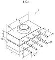
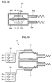
- Fig. 1 is a perspective view showing a jet flow generating apparatus according to an embodiment of the present invention.
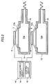
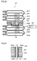
- Fig. 2 is a sectional view showing the jet flow generating apparatus.
- a jet flow generating apparatus 1 has, for example, two independent casings 11 and 12.
- the casings 11 and 12 have vibrating mechanisms 5 and 6, respectively.
- the vibrating mechanisms 5 and 6 have vibration plates 7 and 8, respectively.
- the vibration plates 7 and 8 are composed of a soft film material, for example, PET (polyethylene terephthalate) film or the like.
- the vibrating mechanisms 5 and 6 each have a structure of, for example, a speaker.
- the vibrating mechanisms 5 and 6 each are composed of a coil, a magnet, and so forth (not shown).
- the vibration plates 7 and 8 are asymmetrical with respect to the directions of the vibrations thereof.
- the casings 11 and 12 form chambers 11a and 12a, respectively.
- the chambers 11a and 12a each are filled with a gas.
- a gas for example, air can be used.
- a plurality of nozzles 13 and 14 are disposed as openings on side surfaces of the casings 11 and 12, respectively.
- Each chamber may not have a plurality of nozzles 13 (or nozzles 14) , but one nozzle 13 (or nozzle 14).
- the nozzles such as the nozzle 13 and so forth may not protrude from the casing 11 and so forth, respectively.
- the nozzles such as the nozzle 13 and so forth may be formed in the wall surfaces of the casing 11 and so forth.
- Hole portions 11b and 11b are formed at the upper portions of the casings 11 and 12, respectively.
- the vibrating mechanisms 5 and 6 are disposed so that they cover the hole portions 11b and 12b, respectively.
- the vibrating mechanisms 5 and 6 are controlled by a control unit 10.
- the control unit 10 has a power supply circuit 15 that applies a sinusoidal AC voltage to the vibrating mechanisms 5 and 6, and a control circuit 16 that controls the wave forms of the vibrations of the vibrating mechanisms 5 and 6.
- the control unit 10 causes the control circuit 16 to control the vibrating mechanisms 5 and 6 so that vibrations of air generated by the vibrating mechanisms 5 and 6 are offset or weakened.
- the casings 11 and 12 are made of a highly rigid material such as a metal, for example, aluminum.
- the casings 11 and 12 are formed in, for example, a rectangular parallelepiped shape.
- the shapes, materials, openings, and so forth of the casings 11 and 12 are the same.
- the shapes, materials, and so forth of the vibration plates 7 and 8 are the same.
- the control unit 10 drives the vibrating mechanisms 5 and 6 so as to sinusoidally vibrate them.
- the volumes of the chambers 11a and 12a increase or decrease.
- the internal pressures of the chambers 11a and 12a also vary. Consequently, air streams pulsatively generate through the nozzles 13 and 14.
- the vibration plate 7 deforms in the direction in which the volume of the chamber 11a increases, the internal pressure of the chamber 11a decreases.
- outer air of the casing 11 enters the chamber through the nozzles 13.
- the vibrations of the vibration plates 7 and 8 are propagated as sound waves in air.
- the vibrations of the vibration plates 7 and 8 cause dense and thin portions of air to be formed from the chambers 11a and 12a to the outside.
- a sound wave as a longitudinal wave takes place.
- the sound wave becomes noise.
- the noise sounds are generated mainly from the nozzles 13 and 14.
- the vibrations of the vibration plates 7 and 8 are controlled by the control unit 10 so that the vibrations of air generated by the casings 11 and 12 are offset or weakened each other. Specifically, the vibrations are controlled so that the wave forms of the vibrations of the vibration plates 7 and 8 become the same and the phases thereof become inverse. Thus, since the wave forms weaken each other, the noise of the apparatus can be decreased.
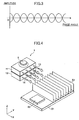
- Fig. 4 is a perspective view showing an example in which heat of, for example, an IC chip is radiated by the jet flow generating apparatus 1.
- the IC chip 50 is disposed in contact with a heat spreader (or a heat transporting member having a heat pipe function).
- a plurality of heat radiation fins 52 is mounted on a heat spreader 51.
- the jet flow generating apparatus 1 is disposed so that the air jet flows of the nozzles 13 and 14 face the heat radiation fins 52.
- the heat generated by the IC chip 50 is spread by the heat spreader 51 and transferred to the heat radiation fins. Then, highly heated air remains in the vicinity of the heat radiation fins 52. As a result, a thermal boundary layer is formed.
- the vibrating mechanisms 5 and 6 vibrate so as to discharge the jet flows generated by the nozzles 13 and 14 toward the heat radiation fins 52. The jet flows break the thermal boundary layer. As a result, the heat is effectively radiated.
- the flow amount of a combined jet flow owing to the vibrations of the vibrating mechanisms such as the vibrating mechanism 5 and so forth can be increased.
- the clock frequencies of IC chips are increased, even if the calorific powers generated thereby are increased, the heat thereof can be effectively radiated.
- control unit 10 controls the phases of the vibrations of the sound waves so that the sound waves weaken each other. In other words, while the heat can be effectively radiated, the noise can be prevented from generating.
- the heat of a heat generating member can be effectively radiated in accordance with the length in the Y direction of the radiation fins such as the heat radiation fins 52 and so forth.
- the vibration plates are sinusoidally vibrated and the sound waves are offset, the sound waves can be more effectively offset than the case that the noise is weakened by two fans that discharge air. Since the sound wave that is output from one fan is generally noisy, it might be difficult to mute the noise with those two fans.
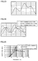
- Fig. 5 is a graph showing an audible characteristic of human.
- the graph is an equi-loudness curve (A characteristic) prescribed by JIS standard.
- the graph represents that in a frequency band from 20 (Hz) to 20 (kHz) , when a human is exposed to the same sound pressure level, how he or she can hear it.
- the graph represents that with reference to a sound wave of 1 (kHz), at what intensity a human can hear sounds of individual frequencies.
- the graph shows that in the same sound pressure level, a human can hear a sound of 50 (Hz) weaker than a sound of 1 (kHz) by 30 (dB).
- the sound pressure level Lp (dB) is defined by the following formula (1).
- Lp 20log(p/p0)
- p represents the sound pressure (Pa)
- p0 represents a reference sound pressure (20 ⁇ Pa).
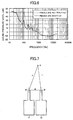
- Fig. 6 is a graph showing a result of the measurement of noise by the jet flow generating apparatus 1 using a sound pressure meter.
- the graph shows a result of the measurement of the sound waves in a frequency band from around 20 (Hz) to 20 (kHz), which is an audible range of human.
- the graph shows "sound pressure level” rather than "noise level " .
- the graph is not compensated with the foregoing A characteristic (the sound pressure level is not compensated in accordance with the audible characteristic of human). Consequently, the graph shown in Fig. 6 represents that as the frequency becomes lower, the sound pressure level becomes higher.
- the noise that humans can hear does not almost vary.
- the graph shows that the sound waves most effectively weaken each other at 100 (Hz).
- the sound waves generated by the nozzles such as the nozzle 13 and so forth do not strengthen each other with almost the maximum amplitude, the noise can be almost prevented from generating.
- the reason why the foregoing effect can be obtained will be described.
- the distance between the opening 13 of the chamber 11a and the opening 14 of the chamber 12a is denoted by d.
- the distance of AP is denoted by h.
- the distance of BP is denoted by i. If
- the triangle definition shows that the maximum limit of
- the shapes of the chambers and so forth are not restricted.
- the number of chambers is 2
- the control unit 10 may cause the wave forms of the sound waves generated in the chambers to have phase differences of 360°/n.
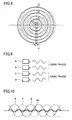
- the phase differences of three wave forms X, Y, and Z need to be shifted by 120° each.
- the combined wave is represented by a solid line W.
- the sound waves weaken each other.
- the distance between openings that are the most spaced apart is ⁇ / ⁇ 2 (n - 1) ⁇ . Since the wave length is sufficiently larger than the distance, the combined wave forms of the sound waves generated in the chambers weaken each other regardless of the positions and directions thereof . In other words, since the maximum amplitudes of the sound waves generated by the openings of the chambers do no strengthen, the noise of the apparatus can be almost prevented from generating.
- the wave forms of the sound waves generated in the chambers A and B have an amplitude a and the same phase
- the amplitude of a sound wave generated in the chamber C is 2 x a
- the phase of the sound wave generated in the chamber C is shifted by 180° (from the phase of each of the sound waves generated in the chambers A and B) .
- the crest portions and the trough portions of the wave forms of the sound waves generated in the chambers A, B, and C weaken each other.
- the combined wave form becomes flat. Consequently, the muting effect can be obtained.
- Fig. 11 is a graph showing combined waves of two sound waves with a parameter of a distance d ranging from ⁇ /180 to ⁇ /2 in the foregoing experiment using the jet flow generating apparatus 1.
- the amplitude on the vertical axis represents a relative value of each parameter value.
- the resultant sound is weaker than the sound of one chamber having one vibration plate.
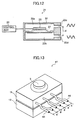
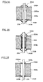
- Fig. 12 is a sectional view showing a jet flow generating apparatus according to another embodiment of the present invention.
- the jet flow generating apparatus according to this embodiment is denoted by reference numeral 21.
- the jet flow generating apparatus 21 is enclosed with one casing 22.
- the space in the casing 22 is partitioned by two chambers 22a and 22b.
- the shapes, volumes, and so forth of the chambers 22a and 22b are almost the same.
- the chambers 22a and 22b compose a chamber group.
- Openings 22c and 22d are formed in the partitioned chambers 22a and 22b, respectively.
- the opening 22c (or 22d) may be one opening or a plurality of openings.
- the shapes, sizes, and so forth of the openings 22c and 22d are almost the same.
- the materials and so forth of the casing 22, the vibration plate 27, and so forth of the jet flow generating apparatus 21 may be the same as those of the jet flow generating apparatus shown in Fig. 1.
- a vibrating mechanism 25 for example, a speaker may be used.
- a control unit 20 that controls the vibrating mechanism 25 includes a power supply circuit and so forth that apply a sinusoidal AC voltage.
- the control unit 20 drives the vibrating mechanism 25 so as to sinusoidally vibrate the vibration plate 27.
- the internal pressures of the chambers 22a and 22b alternately increase and decrease.
- air streams generate through the openings 22c and 22d.
- the air streams alternately flow from the inside to the outside of the casing 22 and from the inside to the outside thereof. Since air is discharged to the outside of the casing 22, the air can be discharged to, for example, a highly heated portion so as to cool it.
- the vibration of the vibration plate 27 propagate as sound waves in air through the openings 22c and 22d.
- the sound waves generated by the openings 22c and 22d are generated from the front surface and the rear surface of the same vibration plate. Since the shapes and so forth of the chambers 22a and 22b are the same as those of the openings 22c and 22d, the wave forms of the sound waves are the same and the phases thereof are inverted. Thus, since the sound waves generated through the openings 22c and 22d are offset, the noise of the apparatus is suppressed.
- the noise of the apparatus can be decreased.
- the jet flow generating apparatus 21 has, for example, three or more vibrating mechanisms as a modification of the embodiment shown in Fig. 12, if the amplitudes and phases of the vibration plates are adjusted, the sound waves weaken each other.
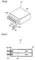
- Fig. 13 is a perspective view showing a jet flow generating apparatus according to another embodiment of the present invention.
- the jet flow generating apparatus according to this embodiment is denoted by reference numeral 41.
- the jet flow generating apparatus 41 has a plurality of nozzles 43 and a plurality of nozzles 44 that are alternately arranged at intervals of a distance d on the two casings 11 and 12.
- the plurality of nozzles 43 and the plurality of nozzles 44 are one-dimensionally arranged.
- the same effect as the jet flow generating apparatuses according to the foregoing embodiments can be obtained.
- the heat radiating process can be effectively performed while the noise is prevented from generating.
- the casings such as the casing 11 and so forth may have a sound absorbing member and a lid member.
- the sound absorbing member for example, glass wool can be used.
- the noise of the apparatus can be further decreased.
- the shapes and materials of the chambers, the shapes of the openings, the shapes of the vibration plates, the shapes, materials, and so forth the vibration plates and the driving devices thereof are the same.
- the shapes and so forth of the chambers and vibration plates may be different from each other.
- the distance between adjacent openings formed in a chamber and the vibrations of the vibrating mechanisms are controlled.
- the wave forms can be adjusted depending on the shapes, materials, and structures of the chambers, and the shapes and so forth of the openings.
- the phases of the sound waves may be controlled.
- the amplitudes and frequencies of the sound waves maybe controlled so as to cause a plurality of the sound waves to weaken each other.
- a speaker is exemplified.
- a vibrating mechanism using a piezoelectric device may be used.
- the jet flow generating apparatuses according to the foregoing embodiments do not always need to have a vibrating mechanism. Instead, a jet flow may be generated by the rotation of a rotor like a roots pump.
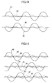
- Fig. 14 is a graph showing wave forms of the sound waves generated in two chambers and whose phases are shifted by 180°. As shown in the graph, since wave forms 31 and 32 as basic frequency components are shifted by 180°, they weaken each other. However, since wave forms 33 and 34 of harmonics of the wave forms 31 and 32 have the same phase, they strengthen each other. Vibrations having harmonic components any integer times higher than the second harmonic component, namely a fourth harmonic, a sixth harmonic, and so forth strengthen each other. Thus, the noise of the apparatus is increased.
- the amplitude of a third harmonic is sufficiently small. In reality, this characteristic can be considered as follows.
- third harmonics strengthen each other, the sound waves of first harmonics and second harmonics are offset.
- the noise level becomes 19.8 (dBA) , which is three times higher than 15 (dBA) .
- This noise level satisfies the target.
- the phases of the sound waves generated in the three chambers are shifted by 120° each. As a result, the noise level can be more decreased than the target value.
- the vibrating mechanisms 65a and 65b are connected to a control unit (not shown) that is the same as the control unit 10 shown in Fig. 2.
- the control unit controls the vibrating mechanisms 65a and 65b so that the phases of the vibrations of the vibrating mechanisms 65a and 65b are inverted and the amplitudes of the vibrations thereof are the same.
- the material, size, shape, volume, and size or shape of opening portions (nozzles) of one chamber formed on the front side of the vibration plate should be the same as those of the other chamber formed on the rear side thereof.
- the sound waves generated in these chambers are inverted.
- the discharge amount of coolant can be further increased.
- the number of casings can be adjusted.
- the discharge amount of coolant can be increased in proportion with the number of casings, only one actuator 203 is required.
- the actuator 203 is disposed at the center of the casings 232A, 232B, 232C, and 232D, namely between the upper casings 232A and 232B, the symmetry of the apparatus is not deteriorated.
- Fig. 38 shows a jet flow generating apparatus according to another modification of the modification (the jet flow generating apparatus 231) shown in Fig. 32.
- the jet flow generating apparatus according to this modification is denoted by reference numeral 251.
- the jet flow generating apparatus 251 uses a driving mechanism in which an actuator 255 drives a piston 255a with the pressure of fluid.
- the fluid is supplied from a fluid supply source 252 to the actuator 255 through a fluid pipe 254 or one of pipes 256 and 257 selected by a selection valve such as a solenoid valve or the like.
- the piston 255a is secured to a rod 209. This structure also allows vibration plates 221A and 221B to vibrate.
- the fluid may be any of solid and gas.
- Fig. 39 shows a jet flow generating apparatus according to another modification of the modification (jet flow generating apparatus 121) shown in Fig. 28.
- the jet flow generating apparatus according to this modification is denoted by reference numeral 261.
- the jet flow generating apparatus 261 has an actuator 265.
- the actuator 265 uses a conventional rotational motor. The rotational motion of the motor is converted into a linear motion of a rod 185 by a link mechanism 266. This structure also allows the vibration plate 145 to vibrate.
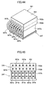
- Fig. 40 is a perspective view showing a jet flow generating apparatus according to another embodiment of the present invention.
- each of the long nozzles 304b Since the flow path of each of the long nozzles 304b is larger than the flowpath of each of the short nozzles 304a, the resistance of the former is larger than that of the latter by the difference between the lengths. However, when the cross section of the flow path is increased, the resistance of the flow path of each of the long nozzles 304b can be prevented from increasing. Thus, coolant can be discharged from the long nozzles 304b with a proper flow amount and a proper flow rate.
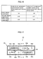
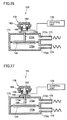
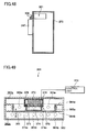
- Fig. 47 and Fig. 48 show an example of the usage of the jet flow generating apparatus having the foregoing bent nozzles.
- the heat sink 247 is disposed outside a case 270 of a computer.
- the jet flow generating apparatus 351 is disposed in the case 270 so that nozzles 309 protrude toward the heat sink 247.
- coolant discharged to a heat sink should be at a low temperature.
- the outer temperature of the case 270 is the lowest.
- the inner temperature of the case 270 is higher than the outside of the case 270 because of heat generated by inner parts of the case 270.
- to cool a CPU disposed in a desktop PC or the like air in the case is discharged to the CPU.
- a heat radiation device that has high efficiency is desired.
- it is preferred to dispose the heat sink and the jet flow generating apparatus outside the case if there is a need to neatly package them because of limited space or desired design, structures shown in Fig. 47 and Fig. 48 can be considered.
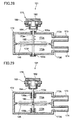
- the edge members are made of, for example, bellows shape resin or rubber.
- the side wall 365a may be formed successively or intermittently in the peripheral direction.
- the casing 362, the vibration plate 365, and the edge member 364a compose a chamber 362a.
- the casing 362, the vibration plate 365, and the edge member 364b compose a chamber 362b.
- the chambers 362a and 362b are structured so that the volume of the chamber 362a is almost the same as the volume of the chamber 362b.
- the chamber 362a has a plurality of openings 363a denoted by dotted circles.
- the chamber 362b has a plurality of openings 363b.
- the openings 363a and 363b may be formed in a nozzle shape as described in each of the foregoing embodiments.
- An actuator 370 is disposed in the chamber 362a.
- the actuator 370 vibrates the vibration plate 365.
- the actuator 370 is composed of a yoke 376, a magnet 372, a plate 373, a coil 378, a movable member 374, and so forth.
- the plate 373 has a function of a yoke.
- the coil 378 is wound on the movable member 374.
- the vibration plate 373 is secured to the movable member 374.
- a control unit 310 is electrically connected to the coil 378.
- the control unit 310 generates a drive signal for the actuator 370.
- Air holes 374a are formed on the side surfaces of the movable member 374.
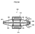
- Fig. 52 is a sectional view showing a speaker type vibrating mechanism used in the foregoing jet flow generating apparatuses according to another embodiment of the present invention.
- the vibrating mechanism according to this embodiment is denoted by reference numeral 280.
- the vibrating mechanism has an actuator 370.
- the actuator 370 is composed of a yoke 376, a magnet 372, a plate 373, a coil 378, a movable member 347, and so forth.
- the plate 373 has a function of a yoke.
- the coil 378 is wound around the movable member 374.
- a vibration plate 285 is secured to the movable member 374.
- the structure of the actuator 370 is the same as that of the actuator 370 shown in Fig. 49 and so forth.
- the yoke 370 of the actuator 370 is mounted on a frame 286 having air holes 286a.
- the vibration plate 285 is also mounted on an opening edge portion of the frame 286 through an
- the jet flow generating apparatus since the area of the vibration plate is proportionally decreased, the amplitude of the vibration plate should be increased so as to increase the discharge amount of coolant.
- the tinsel wire since the tinsel wire becomes short and the amplitude of the vibration plate becomes large, the stress applied to the tinsel wire tends to become large. In other words, the durability of the apparatus tends to deteriorate.
- a lead wire 289 is wired as denoted by a dashed line shown in Fig. 53 (when the lead wire 289 is wired from the center of the vibration plate 285 along the outer periphery), the stress applied to the lead wire 284 is large.
- the tinsel wire 284 when the tinsel wire 284 is spirally wired to the edge member 287, the tinsel wire 284 can be effectively prevented from breaking.
Landscapes
- Engineering & Computer Science (AREA)
- Mechanical Engineering (AREA)
- General Engineering & Computer Science (AREA)
- Physics & Mathematics (AREA)
- Thermal Sciences (AREA)
- Microelectronics & Electronic Packaging (AREA)
- Cooling Or The Like Of Electrical Apparatus (AREA)
- Reciprocating Pumps (AREA)
- Apparatuses For Generation Of Mechanical Vibrations (AREA)
Applications Claiming Priority (6)
| Application Number | Priority Date | Filing Date | Title |
|---|---|---|---|
| JP2003374922 | 2003-11-04 | ||
| JP2003374922 | 2003-11-04 | ||
| JP2004035815 | 2004-02-12 | ||
| JP2004035815 | 2004-02-12 | ||
| JP2004232581A JP4677744B2 (ja) | 2003-11-04 | 2004-08-09 | 噴流発生装置、電子機器及び噴流発生方法 |
| JP2004232581 | 2004-08-09 |
Publications (2)
| Publication Number | Publication Date |
|---|---|
| EP1529963A1 true EP1529963A1 (de) | 2005-05-11 |
| EP1529963B1 EP1529963B1 (de) | 2013-04-03 |
Family
ID=34437604
Family Applications (1)
| Application Number | Title | Priority Date | Filing Date |
|---|---|---|---|
| EP04026088A Expired - Lifetime EP1529963B1 (de) | 2003-11-04 | 2004-11-03 | Vorrichtung zur Erzeugung einer Strahlströmung, elektronische Vorrichtung und Verfahren zur Erzeugung einer Strahlströmung |
Country Status (6)
| Country | Link |
|---|---|
| US (1) | US8033324B2 (de) |
| EP (1) | EP1529963B1 (de) |
| JP (1) | JP4677744B2 (de) |
| KR (1) | KR101120465B1 (de) |
| CN (1) | CN100477898C (de) |
| TW (1) | TWI250840B (de) |
Cited By (11)
| Publication number | Priority date | Publication date | Assignee | Title |
|---|---|---|---|---|
| EP1718141A2 (de) | 2005-04-28 | 2006-11-02 | Sony Corporation | Luftstrom erzeugende Vorrichtung und elektonisches Gehäuse |
| WO2007107921A3 (en) * | 2006-03-21 | 2007-12-13 | Koninkl Philips Electronics Nv | Cooling device and electronic device comprising such a cooling device |
| WO2008053435A1 (en) * | 2006-11-03 | 2008-05-08 | Koninklijke Philips Electronics N.V. | Active control of an acoustic cooling system |
| WO2008065602A1 (en) * | 2006-11-30 | 2008-06-05 | Koninklijke Philips Electronics N.V. | Pulsating cooling system |
| WO2008075245A3 (en) * | 2006-12-15 | 2008-08-21 | Koninkl Philips Electronics Nv | Pulsating fluid cooling with frequency control |
| EP2101351A1 (de) | 2008-03-13 | 2009-09-16 | Siemens Aktiengesellschaft | Kühlvorrichtung zur Kühlung eines Bauteils |
| WO2010044047A1 (en) * | 2008-10-17 | 2010-04-22 | Koninklijke Philips Electronics N.V. | Cooling arrangement |
| US8081454B2 (en) | 2004-03-18 | 2011-12-20 | Sony Corporation | Gas ejector, electronic device, and gas-ejecting method |
| WO2012104648A1 (en) * | 2011-02-03 | 2012-08-09 | The Technology Partnership Plc | Pump |
| CN107559270A (zh) * | 2017-09-08 | 2018-01-09 | 浙江大学 | 合成射流平板湍流减阻装置 |
| CN113597192A (zh) * | 2020-04-30 | 2021-11-02 | 维沃移动通信有限公司 | 一种电子设备 |
Families Citing this family (64)
| Publication number | Priority date | Publication date | Assignee | Title |
|---|---|---|---|---|
| JP4298746B2 (ja) * | 2003-02-20 | 2009-07-22 | コーニンクレッカ フィリップス エレクトロニクス エヌ ヴィ | マイクロ・ジェットを備える冷却アセンブリ |
| US20060196638A1 (en) * | 2004-07-07 | 2006-09-07 | Georgia Tech Research Corporation | System and method for thermal management using distributed synthetic jet actuators |
| JP5088526B2 (ja) * | 2005-04-18 | 2012-12-05 | ソニー株式会社 | 噴流発生装置及び電子機器 |
| US20070023169A1 (en) * | 2005-07-29 | 2007-02-01 | Innovative Fluidics, Inc. | Synthetic jet ejector for augmentation of pumped liquid loop cooling and enhancement of pool and flow boiling |
| US8069910B2 (en) * | 2005-10-12 | 2011-12-06 | Nuventix, Inc. | Acoustic resonator for synthetic jet generation for thermal management |
| KR20080059594A (ko) * | 2005-10-28 | 2008-06-30 | 산요덴키가부시키가이샤 | 유체 이송 장치 및 이를 이용한 연료 전지 및 전자 기기 |
| US7607470B2 (en) * | 2005-11-14 | 2009-10-27 | Nuventix, Inc. | Synthetic jet heat pipe thermal management system |
| JP4867324B2 (ja) * | 2005-12-12 | 2012-02-01 | ソニー株式会社 | 放熱装置及び電子機器 |
| JP4844236B2 (ja) * | 2005-12-20 | 2011-12-28 | ソニー株式会社 | ノズル、噴流発生装置、冷却装置及び電子機器 |
| JP5003018B2 (ja) * | 2006-03-01 | 2012-08-15 | ソニー株式会社 | 噴流発生装置 |
| US7787248B2 (en) * | 2006-06-26 | 2010-08-31 | International Business Machines Corporation | Multi-fluid cooling system, cooled electronics module, and methods of fabrication thereof |
| US7841385B2 (en) * | 2006-06-26 | 2010-11-30 | International Business Machines Corporation | Dual-chamber fluid pump for a multi-fluid electronics cooling system and method |
| JP2008008230A (ja) * | 2006-06-30 | 2008-01-17 | Sony Corp | 噴流発生装置、ノズル体及び電子機器 |
| US20080137289A1 (en) * | 2006-12-08 | 2008-06-12 | General Electric Company | Thermal management system for embedded environment and method for making same |
| JP2008280917A (ja) | 2007-05-10 | 2008-11-20 | Alps Electric Co Ltd | 圧電式気体噴射装置 |
| KR101555890B1 (ko) * | 2007-06-14 | 2015-09-30 | 코닌클리케 필립스 엔.브이. | 맥동 유체 냉각을 갖는 조명 장치 |
| KR20100053536A (ko) | 2007-06-29 | 2010-05-20 | 아트피셜 머슬, 인코퍼레이션 | 감각적 피드백을 부여하는 전기활성 고분자 변환기 |
| US20090084866A1 (en) * | 2007-10-01 | 2009-04-02 | Nuventix Inc. | Vibration balanced synthetic jet ejector |
| KR101540596B1 (ko) * | 2007-12-07 | 2015-07-30 | 코닌클리케 필립스 엔.브이. | 저잡음 냉각 장치 |
| US7990705B2 (en) * | 2008-05-09 | 2011-08-02 | General Electric Company | Systems and methods for synthetic jet enhanced natural cooling |
| EP2322019A1 (de) * | 2008-09-12 | 2011-05-18 | Koninklijke Philips Electronics N.V. | Vorrichtung mit lückenartigem raum und daran gekoppelter synthetischer strahlgenerator |
| US8453715B2 (en) * | 2008-10-30 | 2013-06-04 | General Electric Company | Synthetic jet embedded heat sink |
| US9615482B2 (en) | 2009-12-11 | 2017-04-04 | General Electric Company | Shaped heat sinks to optimize flow |
| US10274263B2 (en) | 2009-04-09 | 2019-04-30 | General Electric Company | Method and apparatus for improved cooling of a heat sink using a synthetic jet |
| US8496049B2 (en) * | 2009-04-09 | 2013-07-30 | General Electric Company | Heat sinks with distributed and integrated jet cooling |
| US8584735B2 (en) * | 2009-07-28 | 2013-11-19 | Aerojet Rocketdyne Of De, Inc. | Cooling device and method with synthetic jet actuator |
| US8490419B2 (en) * | 2009-08-20 | 2013-07-23 | United States Thermoelectric Consortium | Interlocked jets cooling method and apparatus |
| US8776871B2 (en) * | 2009-11-19 | 2014-07-15 | General Electric Company | Chassis with distributed jet cooling |
| JP5868015B2 (ja) * | 2010-04-14 | 2016-02-24 | ゼネラル・エレクトリック・カンパニイ | 分散型ジェット冷却を備えたシャーシ |
| WO2012118916A2 (en) | 2011-03-01 | 2012-09-07 | Bayer Materialscience Ag | Automated manufacturing processes for producing deformable polymer devices and films |
| US20120285667A1 (en) * | 2011-05-13 | 2012-11-15 | Lighting Science Group Corporation | Sound baffling cooling system for led thermal management and associated methods |
| EP2740936B1 (de) * | 2011-08-05 | 2016-09-07 | Panasonic Corporation | Brennstoffzellensystem |
| US20130243030A1 (en) * | 2012-03-16 | 2013-09-19 | Nuventix, Inc. | Augmentation of Fans With Synthetic Jet Ejectors |
| TW201339808A (zh) * | 2012-03-16 | 2013-10-01 | Inventec Corp | 電子裝置 |
| WO2013142552A1 (en) | 2012-03-21 | 2013-09-26 | Bayer Materialscience Ag | Roll-to-roll manufacturing processes for producing self-healing electroactive polymer devices |
| AU2013245946A1 (en) | 2012-04-10 | 2014-11-27 | Eyenovia, Inc. | Spray ejector mechanisms and devices providing charge isolation and controllable droplet charge, and low dosage volume opthalmic administration |
| JP6240170B2 (ja) * | 2012-05-15 | 2017-11-29 | アイノビア,インコーポレイティド | エジェクタ装置,並びにその方法,ドライバ,及び回路 |
| WO2013192143A1 (en) | 2012-06-18 | 2013-12-27 | Bayer Intellectual Property Gmbh | Stretch frame for stretching process |
| US20140002991A1 (en) * | 2012-06-29 | 2014-01-02 | General Electric Company | Thermal management in optical and electronic devices |
| US8976525B2 (en) * | 2012-07-31 | 2015-03-10 | General Electric Company | Systems and methods for dissipating heat in an enclosure |
| US9215520B2 (en) * | 2012-08-15 | 2015-12-15 | General Electric Company | Multi-function synthetic jet and method of manufacturing same |
| US9590193B2 (en) | 2012-10-24 | 2017-03-07 | Parker-Hannifin Corporation | Polymer diode |
| TW201447217A (zh) * | 2013-03-15 | 2014-12-16 | Bayer Materialscience Ag | 電活性聚合物致動的氣流熱管理模組 |
| US20140376185A1 (en) * | 2013-06-19 | 2014-12-25 | Fairchild Korea Semiconductor Ltd. | Cooling device |
| US20150041104A1 (en) * | 2013-08-09 | 2015-02-12 | Ge Aviation Systems, Llc | Systems and methods for robust and modular synthetic jet cooling |
| US9027702B2 (en) * | 2013-10-16 | 2015-05-12 | The Boeing Company | Synthetic jet muffler |
| US10085363B2 (en) * | 2014-05-22 | 2018-09-25 | General Electric Company | Integrated compact impingement on extended heat surface |
| US9951767B2 (en) | 2014-05-22 | 2018-04-24 | General Electric Company | Vibrational fluid mover active controller |
| KR101651018B1 (ko) * | 2014-12-08 | 2016-08-24 | 엘지전자 주식회사 | 전자기 구동 기체 분출 장치 |
| US10629514B2 (en) * | 2015-12-09 | 2020-04-21 | Ozyegin Universitesi | Heat sink cooling with preferred synthetic jet cooling devices |
| CN105491854B (zh) * | 2015-12-29 | 2018-02-06 | 东南大学 | 一种多方向出口射流散热器 |
| US10502246B2 (en) * | 2016-04-25 | 2019-12-10 | Rensselaer Polytechnic Institute | Methods and apparatus for controlling flow fields |
| CN107148193B (zh) * | 2016-09-29 | 2019-07-09 | 宁波三星医疗电气股份有限公司 | 一种充电桩及充电桩散热控制方法 |
| TWI650284B (zh) * | 2017-09-30 | 2019-02-11 | Microjet Technology Co., Ltd | 流體裝置之控制方法 |
| DE102018100279B3 (de) | 2018-01-08 | 2019-04-18 | Beuth Hochschule Für Technik Berlin | Lüftervorrichtung zum Wärmeabtransport von einem Gegenstand und Gegenstand |
| KR102595131B1 (ko) * | 2018-11-07 | 2023-10-30 | 삼성전자주식회사 | 전자 장치 및 그 제어 방법 |
| US10827273B2 (en) | 2018-11-27 | 2020-11-03 | Apple Inc. | Dual loudspeaker enabled cooling |
| CN110162157A (zh) * | 2019-03-29 | 2019-08-23 | 联想(北京)有限公司 | 散热系统 |
| US11898545B2 (en) * | 2019-06-21 | 2024-02-13 | Brane Audio, LLC | Venturi pump systems and methods to use same |
| CN113765496A (zh) * | 2020-06-04 | 2021-12-07 | 中兴通讯股份有限公司 | 散热组件、散热结构以及散热方法、电子设备和装置 |
| GB2583880A (en) | 2020-07-31 | 2020-11-11 | Ttp Ventus Ltd | Actuator for a resonant acoustic pump |
| CN115023097B (zh) * | 2021-09-30 | 2023-04-07 | 荣耀终端有限公司 | 射流发生装置及方法、散热器以及电子设备 |
| CN116156855B (zh) * | 2023-04-11 | 2025-07-04 | 西安交通大学 | 电子器件散热装置 |
| CN117222209B (zh) * | 2023-11-09 | 2024-02-20 | 东莞市富其扬电子科技有限公司 | 一种液冷散热器 |
Citations (1)
| Publication number | Priority date | Publication date | Assignee | Title |
|---|---|---|---|---|
| WO2003036098A1 (de) * | 2001-10-23 | 2003-05-01 | Wilhelm Zackl | Ventillose pumpe |
Family Cites Families (32)
| Publication number | Priority date | Publication date | Assignee | Title |
|---|---|---|---|---|
| US3029743A (en) * | 1960-04-14 | 1962-04-17 | Curtiss Wright Corp | Ceramic diaphragm pump |
| GB1583758A (en) * | 1976-10-01 | 1981-02-04 | Nat Res Dev | Attenuation of sound waves in ducts |
| JPS5514920A (en) * | 1978-07-17 | 1980-02-01 | Aisin Seiki Co Ltd | Diaprhagm type air pump unit |
| JPS55101800A (en) * | 1979-01-25 | 1980-08-04 | Pioneer Electronic Corp | Air pump |
| JPS58140491A (ja) * | 1982-02-16 | 1983-08-20 | Matsushita Electric Ind Co Ltd | 流れ発生装置 |
| JPS6085043A (ja) * | 1983-10-18 | 1985-05-14 | Bridgestone Corp | 自動車等のエンジン騒音制御装置 |
| US4648807A (en) * | 1985-05-14 | 1987-03-10 | The Garrett Corporation | Compact piezoelectric fluidic air supply pump |
| US4665549A (en) * | 1985-12-18 | 1987-05-12 | Nelson Industries Inc. | Hybrid active silencer |
| JPS62159798A (ja) * | 1986-01-08 | 1987-07-15 | Matsushita Electric Ind Co Ltd | 流体駆動装置 |
| JPS62159799A (ja) * | 1986-01-08 | 1987-07-15 | Matsushita Electric Ind Co Ltd | 流体駆動装置 |
| US4923031A (en) * | 1986-02-26 | 1990-05-08 | Electro-Voice, Incorporated | High output loudspeaker system |
| IT1211848B (it) * | 1987-10-12 | 1989-11-03 | Roma A | Dispositivo silenziatore per scarichi di motori e simili,ad interferenza acustica |
| US5077601A (en) * | 1988-09-09 | 1991-12-31 | Hitachi, Ltd. | Cooling system for cooling an electronic device and heat radiation fin for use in the cooling system |
| JPH02213200A (ja) * | 1989-02-14 | 1990-08-24 | Victor Co Of Japan Ltd | 熱交換器 |
| DE3917116A1 (de) | 1989-05-26 | 1990-11-29 | Hartung Kuhn & Co Maschf | Fuellwagen fuer eine koksofenbatterie |
| JPH03116961A (ja) | 1989-09-29 | 1991-05-17 | Victor Co Of Japan Ltd | 放熱装置 |
| JPH0635515Y2 (ja) * | 1990-06-26 | 1994-09-14 | 呉羽化学工業株式会社 | 電気部品の冷却装置 |
| US5270484A (en) * | 1990-09-14 | 1993-12-14 | Canon Kabushiki Kaisha | Powder conveying device |
| JPH05173988A (ja) | 1991-12-26 | 1993-07-13 | Toshiba Corp | 分散処理方式および該分散処理に適用されるトランザクション処理方式 |
| US5692054A (en) * | 1992-10-08 | 1997-11-25 | Noise Cancellation Technologies, Inc. | Multiple source self noise cancellation |
| JPH06309262A (ja) | 1993-04-26 | 1994-11-04 | Mitsubishi Electric Corp | 分散サービス制御システム |
| DE59510549D1 (de) * | 1995-03-14 | 2003-03-13 | Sulzer Markets & Technology Ag | Verfahren zum aktiven Dämpfen globaler Strömungsoszillationen in abgelösten instabilen Strömungen und Vorrichtung zur Anwendung des Verfahrens |
| JP2703515B2 (ja) * | 1995-03-30 | 1998-01-26 | 世晃産業株式会社 | 電磁振動型のダイヤフラム式エアポンプの消音タンク |
| JP3437882B2 (ja) * | 1995-05-19 | 2003-08-18 | 富士通株式会社 | 能動騒音制御システムを備えた電子機器 |
| US6123145A (en) * | 1995-06-12 | 2000-09-26 | Georgia Tech Research Corporation | Synthetic jet actuators for cooling heated bodies and environments |
| US5758823A (en) * | 1995-06-12 | 1998-06-02 | Georgia Tech Research Corporation | Synthetic jet actuator and applications thereof |
| JP4306097B2 (ja) * | 2000-06-27 | 2009-07-29 | ミツミ電機株式会社 | 小型ポンプ |
| JP2002070728A (ja) * | 2000-09-04 | 2002-03-08 | Calsonic Kansei Corp | 斜板式圧縮機の脈動低減構造 |
| US6519151B2 (en) * | 2001-06-27 | 2003-02-11 | International Business Machines Corporation | Conic-sectioned plate and jet nozzle assembly for use in cooling an electronic module, and methods of fabrication thereof |
| US6588497B1 (en) * | 2002-04-19 | 2003-07-08 | Georgia Tech Research Corporation | System and method for thermal management by synthetic jet ejector channel cooling techniques |
| US6937472B2 (en) * | 2003-05-09 | 2005-08-30 | Intel Corporation | Apparatus for cooling heat generating components within a computer system enclosure |
| WO2005008348A2 (en) | 2003-07-07 | 2005-01-27 | Georgia Tech Research Corporation | System and method for thermal management using distributed synthetic jet actuators |
-
2004
- 2004-08-09 JP JP2004232581A patent/JP4677744B2/ja not_active Expired - Fee Related
- 2004-11-03 US US10/982,283 patent/US8033324B2/en not_active Expired - Fee Related
- 2004-11-03 EP EP04026088A patent/EP1529963B1/de not_active Expired - Lifetime
- 2004-11-04 TW TW093133661A patent/TWI250840B/zh not_active IP Right Cessation
- 2004-11-04 KR KR1020040089375A patent/KR101120465B1/ko not_active Expired - Fee Related
- 2004-11-04 CN CNB2004101023295A patent/CN100477898C/zh not_active Expired - Fee Related
Patent Citations (1)
| Publication number | Priority date | Publication date | Assignee | Title |
|---|---|---|---|---|
| WO2003036098A1 (de) * | 2001-10-23 | 2003-05-01 | Wilhelm Zackl | Ventillose pumpe |
Cited By (17)
| Publication number | Priority date | Publication date | Assignee | Title |
|---|---|---|---|---|
| US8081454B2 (en) | 2004-03-18 | 2011-12-20 | Sony Corporation | Gas ejector, electronic device, and gas-ejecting method |
| EP1718141A2 (de) | 2005-04-28 | 2006-11-02 | Sony Corporation | Luftstrom erzeugende Vorrichtung und elektonisches Gehäuse |
| EP1718141A3 (de) * | 2005-04-28 | 2008-07-30 | Sony Corporation | Luftstrom erzeugende Vorrichtung und elektronisches Gehäuse |
| US7861767B2 (en) | 2005-04-28 | 2011-01-04 | Sony Corporation | Airflow generating device and electronic apparatus |
| WO2007107921A3 (en) * | 2006-03-21 | 2007-12-13 | Koninkl Philips Electronics Nv | Cooling device and electronic device comprising such a cooling device |
| WO2008053435A1 (en) * | 2006-11-03 | 2008-05-08 | Koninklijke Philips Electronics N.V. | Active control of an acoustic cooling system |
| WO2008065602A1 (en) * | 2006-11-30 | 2008-06-05 | Koninklijke Philips Electronics N.V. | Pulsating cooling system |
| WO2008075245A3 (en) * | 2006-12-15 | 2008-08-21 | Koninkl Philips Electronics Nv | Pulsating fluid cooling with frequency control |
| US7859842B2 (en) | 2008-03-13 | 2010-12-28 | Siemens Aktiengesellschaft | Cooling facility for cooling a component |
| EP2101351A1 (de) | 2008-03-13 | 2009-09-16 | Siemens Aktiengesellschaft | Kühlvorrichtung zur Kühlung eines Bauteils |
| WO2010044047A1 (en) * | 2008-10-17 | 2010-04-22 | Koninklijke Philips Electronics N.V. | Cooling arrangement |
| WO2012104648A1 (en) * | 2011-02-03 | 2012-08-09 | The Technology Partnership Plc | Pump |
| US10975855B2 (en) | 2011-02-03 | 2021-04-13 | The Technology Partnership Plc. | Fluid pump including a pressure oscillation with at least one nodal diameter |
| CN107559270A (zh) * | 2017-09-08 | 2018-01-09 | 浙江大学 | 合成射流平板湍流减阻装置 |
| CN107559270B (zh) * | 2017-09-08 | 2023-11-14 | 浙江大学 | 合成射流平板湍流减阻装置 |
| CN113597192A (zh) * | 2020-04-30 | 2021-11-02 | 维沃移动通信有限公司 | 一种电子设备 |
| CN113597192B (zh) * | 2020-04-30 | 2024-02-02 | 维沃移动通信有限公司 | 一种电子设备 |
Also Published As
| Publication number | Publication date |
|---|---|
| US20050121171A1 (en) | 2005-06-09 |
| US8033324B2 (en) | 2011-10-11 |
| CN1671279A (zh) | 2005-09-21 |
| KR101120465B1 (ko) | 2012-02-29 |
| JP4677744B2 (ja) | 2011-04-27 |
| KR20050043676A (ko) | 2005-05-11 |
| TW200531618A (en) | 2005-09-16 |
| JP2005256834A (ja) | 2005-09-22 |
| TWI250840B (en) | 2006-03-01 |
| CN100477898C (zh) | 2009-04-08 |
| EP1529963B1 (de) | 2013-04-03 |
Similar Documents
| Publication | Publication Date | Title |
|---|---|---|
| EP1529963B1 (de) | Vorrichtung zur Erzeugung einer Strahlströmung, elektronische Vorrichtung und Verfahren zur Erzeugung einer Strahlströmung | |
| EP1762725B1 (de) | Gasstrahlvorrichtung, elektronische vorrichtung und gasstrahlverfahren | |
| KR101295488B1 (ko) | 분류 발생 장치 및 전자 기기 | |
| US7972124B2 (en) | Piezoelectric micro-blower | |
| JP2014037826A (ja) | 多機能シンセティックジェットおよび同製作の方法 | |
| JP2006320887A (ja) | 振動装置、噴流発生装置、電子機器及び振動装置の製造方法 | |
| US20110168361A1 (en) | Heat dissipation device and airflow generator thereof | |
| CN100399232C (zh) | 气流产生装置和电子设备 | |
| CN101171896A (zh) | 振动装置、射流产生装置、电子器件以及振动装置的制造方法 | |
| JP4867324B2 (ja) | 放熱装置及び電子機器 | |
| JP2007142360A (ja) | 放熱装置及び電子機器 | |
| JP2006310673A (ja) | 噴流発生装置、ヒートシンク、冷却装置及び電子機器 | |
| JP4900503B2 (ja) | 気体噴出装置及び電子機器 | |
| JP2007209845A (ja) | 噴流発生装置及び電子機器 | |
| JP2007154784A (ja) | 噴流発生装置及び電子機器 |
Legal Events
| Date | Code | Title | Description |
|---|---|---|---|
| PUAI | Public reference made under article 153(3) epc to a published international application that has entered the european phase |
Free format text: ORIGINAL CODE: 0009012 |
|
| AK | Designated contracting states |
Kind code of ref document: A1 Designated state(s): AT BE BG CH CY CZ DE DK EE ES FI FR GB GR HU IE IS IT LI LU MC NL PL PT RO SE SI SK TR |
|
| AX | Request for extension of the european patent |
Extension state: AL HR LT LV MK YU |
|
| 17P | Request for examination filed |
Effective date: 20051012 |
|
| AKX | Designation fees paid |
Designated state(s): DE FR GB |
|
| 17Q | First examination report despatched |
Effective date: 20071220 |
|
| GRAP | Despatch of communication of intention to grant a patent |
Free format text: ORIGINAL CODE: EPIDOSNIGR1 |
|
| RAP1 | Party data changed (applicant data changed or rights of an application transferred) |
Owner name: SONY CORPORATION |
|
| GRAP | Despatch of communication of intention to grant a patent |
Free format text: ORIGINAL CODE: EPIDOSNIGR1 |
|
| RIN1 | Information on inventor provided before grant (corrected) |
Inventor name: MUKASA, TOMOHARU Inventor name: HORI, KAZUHITO Inventor name: YOKOMIZO, KANJI Inventor name: ISHIKAWA, HIROICHI Inventor name: NAKAYAMA, NORIKAZU |
|
| GRAS | Grant fee paid |
Free format text: ORIGINAL CODE: EPIDOSNIGR3 |
|
| GRAA | (expected) grant |
Free format text: ORIGINAL CODE: 0009210 |
|
| AK | Designated contracting states |
Kind code of ref document: B1 Designated state(s): DE FR GB |
|
| REG | Reference to a national code |
Ref country code: GB Ref legal event code: FG4D |
|
| REG | Reference to a national code |
Ref country code: DE Ref legal event code: R096 Ref document number: 602004041553 Country of ref document: DE Effective date: 20130529 |
|
| PLBE | No opposition filed within time limit |
Free format text: ORIGINAL CODE: 0009261 |
|
| STAA | Information on the status of an ep patent application or granted ep patent |
Free format text: STATUS: NO OPPOSITION FILED WITHIN TIME LIMIT |
|
| 26N | No opposition filed |
Effective date: 20140106 |
|
| REG | Reference to a national code |
Ref country code: DE Ref legal event code: R097 Ref document number: 602004041553 Country of ref document: DE Effective date: 20140106 |
|
| PGFP | Annual fee paid to national office [announced via postgrant information from national office to epo] |
Ref country code: DE Payment date: 20141119 Year of fee payment: 11 Ref country code: GB Payment date: 20141119 Year of fee payment: 11 Ref country code: FR Payment date: 20141119 Year of fee payment: 11 |
|
| REG | Reference to a national code |
Ref country code: DE Ref legal event code: R119 Ref document number: 602004041553 Country of ref document: DE |
|
| GBPC | Gb: european patent ceased through non-payment of renewal fee |
Effective date: 20151103 |
|
| REG | Reference to a national code |
Ref country code: FR Ref legal event code: ST Effective date: 20160729 |
|
| PG25 | Lapsed in a contracting state [announced via postgrant information from national office to epo] |
Ref country code: DE Free format text: LAPSE BECAUSE OF NON-PAYMENT OF DUE FEES Effective date: 20160601 Ref country code: GB Free format text: LAPSE BECAUSE OF NON-PAYMENT OF DUE FEES Effective date: 20151103 |
|
| PG25 | Lapsed in a contracting state [announced via postgrant information from national office to epo] |
Ref country code: FR Free format text: LAPSE BECAUSE OF NON-PAYMENT OF DUE FEES Effective date: 20151130 |