EP1529660B1 - Laufflächenprofil eines Winterreifens - Google Patents
Laufflächenprofil eines Winterreifens Download PDFInfo
- Publication number
- EP1529660B1 EP1529660B1 EP05001621A EP05001621A EP1529660B1 EP 1529660 B1 EP1529660 B1 EP 1529660B1 EP 05001621 A EP05001621 A EP 05001621A EP 05001621 A EP05001621 A EP 05001621A EP 1529660 B1 EP1529660 B1 EP 1529660B1
- Authority
- EP
- European Patent Office
- Prior art keywords
- tread block
- tread
- vehicle
- tyre
- shoulder
- Prior art date
- Legal status (The legal status is an assumption and is not a legal conclusion. Google has not performed a legal analysis and makes no representation as to the accuracy of the status listed.)
- Expired - Lifetime
Links
- 238000003475 lamination Methods 0.000 claims 9
- 241000826860 Trapezium Species 0.000 claims 2
- 241000446313 Lamella Species 0.000 abstract description 18
- 230000002093 peripheral effect Effects 0.000 abstract description 3
- 230000010363 phase shift Effects 0.000 description 5
- 230000003247 decreasing effect Effects 0.000 description 4
- 230000002787 reinforcement Effects 0.000 description 3
- 230000008094 contradictory effect Effects 0.000 description 2
- 239000004677 Nylon Substances 0.000 description 1
- 229910000831 Steel Inorganic materials 0.000 description 1
- 239000004760 aramid Substances 0.000 description 1
- 229920003235 aromatic polyamide Polymers 0.000 description 1
- 230000015572 biosynthetic process Effects 0.000 description 1
- 238000010276 construction Methods 0.000 description 1
- 239000000463 material Substances 0.000 description 1
- 229920001778 nylon Polymers 0.000 description 1
- 239000010959 steel Substances 0.000 description 1
- 238000009423 ventilation Methods 0.000 description 1
- 238000013022 venting Methods 0.000 description 1
- XLYOFNOQVPJJNP-UHFFFAOYSA-N water Substances O XLYOFNOQVPJJNP-UHFFFAOYSA-N 0.000 description 1
Images


Classifications
-
- B—PERFORMING OPERATIONS; TRANSPORTING
- B60—VEHICLES IN GENERAL
- B60C—VEHICLE TYRES; TYRE INFLATION; TYRE CHANGING; CONNECTING VALVES TO INFLATABLE ELASTIC BODIES IN GENERAL; DEVICES OR ARRANGEMENTS RELATED TO TYRES
- B60C11/00—Tyre tread bands; Tread patterns; Anti-skid inserts
- B60C11/03—Tread patterns
- B60C11/12—Tread patterns characterised by the use of narrow slits or incisions, e.g. sipes
-
- B—PERFORMING OPERATIONS; TRANSPORTING
- B60—VEHICLES IN GENERAL
- B60C—VEHICLE TYRES; TYRE INFLATION; TYRE CHANGING; CONNECTING VALVES TO INFLATABLE ELASTIC BODIES IN GENERAL; DEVICES OR ARRANGEMENTS RELATED TO TYRES
- B60C11/00—Tyre tread bands; Tread patterns; Anti-skid inserts
- B60C11/03—Tread patterns
- B60C11/0304—Asymmetric patterns
-
- B—PERFORMING OPERATIONS; TRANSPORTING
- B60—VEHICLES IN GENERAL
- B60C—VEHICLE TYRES; TYRE INFLATION; TYRE CHANGING; CONNECTING VALVES TO INFLATABLE ELASTIC BODIES IN GENERAL; DEVICES OR ARRANGEMENTS RELATED TO TYRES
- B60C11/00—Tyre tread bands; Tread patterns; Anti-skid inserts
- B60C11/03—Tread patterns
- B60C11/11—Tread patterns in which the raised area of the pattern consists only of isolated elements, e.g. blocks
-
- B—PERFORMING OPERATIONS; TRANSPORTING
- B60—VEHICLES IN GENERAL
- B60C—VEHICLE TYRES; TYRE INFLATION; TYRE CHANGING; CONNECTING VALVES TO INFLATABLE ELASTIC BODIES IN GENERAL; DEVICES OR ARRANGEMENTS RELATED TO TYRES
- B60C11/00—Tyre tread bands; Tread patterns; Anti-skid inserts
- B60C11/03—Tread patterns
- B60C11/12—Tread patterns characterised by the use of narrow slits or incisions, e.g. sipes
- B60C11/1204—Tread patterns characterised by the use of narrow slits or incisions, e.g. sipes with special shape of the sipe
- B60C11/1218—Three-dimensional shape with regard to depth and extending direction
-
- B—PERFORMING OPERATIONS; TRANSPORTING
- B60—VEHICLES IN GENERAL
- B60C—VEHICLE TYRES; TYRE INFLATION; TYRE CHANGING; CONNECTING VALVES TO INFLATABLE ELASTIC BODIES IN GENERAL; DEVICES OR ARRANGEMENTS RELATED TO TYRES
- B60C11/00—Tyre tread bands; Tread patterns; Anti-skid inserts
- B60C11/03—Tread patterns
- B60C11/12—Tread patterns characterised by the use of narrow slits or incisions, e.g. sipes
- B60C11/1236—Tread patterns characterised by the use of narrow slits or incisions, e.g. sipes with special arrangements in the tread pattern
- B60C11/124—Tread patterns characterised by the use of narrow slits or incisions, e.g. sipes with special arrangements in the tread pattern inclined with regard to a plane normal to the tread surface
-
- B—PERFORMING OPERATIONS; TRANSPORTING
- B60—VEHICLES IN GENERAL
- B60C—VEHICLE TYRES; TYRE INFLATION; TYRE CHANGING; CONNECTING VALVES TO INFLATABLE ELASTIC BODIES IN GENERAL; DEVICES OR ARRANGEMENTS RELATED TO TYRES
- B60C11/00—Tyre tread bands; Tread patterns; Anti-skid inserts
- B60C11/03—Tread patterns
- B60C11/12—Tread patterns characterised by the use of narrow slits or incisions, e.g. sipes
- B60C11/1259—Depth of the sipe
- B60C11/1263—Depth of the sipe different within the same sipe
-
- B—PERFORMING OPERATIONS; TRANSPORTING
- B60—VEHICLES IN GENERAL
- B60C—VEHICLE TYRES; TYRE INFLATION; TYRE CHANGING; CONNECTING VALVES TO INFLATABLE ELASTIC BODIES IN GENERAL; DEVICES OR ARRANGEMENTS RELATED TO TYRES
- B60C11/00—Tyre tread bands; Tread patterns; Anti-skid inserts
- B60C11/03—Tread patterns
- B60C11/0327—Tread patterns characterised by special properties of the tread pattern
- B60C2011/0334—Stiffness
-
- B—PERFORMING OPERATIONS; TRANSPORTING
- B60—VEHICLES IN GENERAL
- B60C—VEHICLE TYRES; TYRE INFLATION; TYRE CHANGING; CONNECTING VALVES TO INFLATABLE ELASTIC BODIES IN GENERAL; DEVICES OR ARRANGEMENTS RELATED TO TYRES
- B60C11/00—Tyre tread bands; Tread patterns; Anti-skid inserts
- B60C11/03—Tread patterns
- B60C11/12—Tread patterns characterised by the use of narrow slits or incisions, e.g. sipes
- B60C11/1204—Tread patterns characterised by the use of narrow slits or incisions, e.g. sipes with special shape of the sipe
- B60C2011/1213—Tread patterns characterised by the use of narrow slits or incisions, e.g. sipes with special shape of the sipe sinusoidal or zigzag at the tread surface
-
- B—PERFORMING OPERATIONS; TRANSPORTING
- B60—VEHICLES IN GENERAL
- B60C—VEHICLE TYRES; TYRE INFLATION; TYRE CHANGING; CONNECTING VALVES TO INFLATABLE ELASTIC BODIES IN GENERAL; DEVICES OR ARRANGEMENTS RELATED TO TYRES
- B60C11/00—Tyre tread bands; Tread patterns; Anti-skid inserts
- B60C11/03—Tread patterns
- B60C11/12—Tread patterns characterised by the use of narrow slits or incisions, e.g. sipes
- B60C11/1204—Tread patterns characterised by the use of narrow slits or incisions, e.g. sipes with special shape of the sipe
- B60C2011/1231—Tread patterns characterised by the use of narrow slits or incisions, e.g. sipes with special shape of the sipe being shallow, i.e. sipe depth of less than 3 mm
-
- B—PERFORMING OPERATIONS; TRANSPORTING
- B60—VEHICLES IN GENERAL
- B60C—VEHICLE TYRES; TYRE INFLATION; TYRE CHANGING; CONNECTING VALVES TO INFLATABLE ELASTIC BODIES IN GENERAL; DEVICES OR ARRANGEMENTS RELATED TO TYRES
- B60C11/00—Tyre tread bands; Tread patterns; Anti-skid inserts
- B60C11/03—Tread patterns
- B60C11/12—Tread patterns characterised by the use of narrow slits or incisions, e.g. sipes
- B60C11/1259—Depth of the sipe
- B60C2011/1268—Depth of the sipe being different from sipe to sipe
-
- Y—GENERAL TAGGING OF NEW TECHNOLOGICAL DEVELOPMENTS; GENERAL TAGGING OF CROSS-SECTIONAL TECHNOLOGIES SPANNING OVER SEVERAL SECTIONS OF THE IPC; TECHNICAL SUBJECTS COVERED BY FORMER USPC CROSS-REFERENCE ART COLLECTIONS [XRACs] AND DIGESTS
- Y10—TECHNICAL SUBJECTS COVERED BY FORMER USPC
- Y10S—TECHNICAL SUBJECTS COVERED BY FORMER USPC CROSS-REFERENCE ART COLLECTIONS [XRACs] AND DIGESTS
- Y10S152/00—Resilient tires and wheels
- Y10S152/03—Slits in threads
Definitions
- the invention relates to a tread pattern of a winter tire.
- Winter tires are subject to different contradictory requirements. So a winter tire should ensure good grip on snow and ice as well as summer tires good handling properties. These targets require contradictory measures in the construction of the winter tire, so that either a winter tire with good winter properties with good grip on ice and snow and relatively poor handling on dry roads or a summer tire with good handling on dry roads, but with relatively poor winter properties arises.
- a winter tire having the features of the preamble of claim 1 is known from US 5,660,651 A known.
- the invention has for its object to provide a tread pattern of a winter tire that allows both good winter properties with good grip on ice and snow and good handling on dry roads.
- the object is achieved by forming the tread pattern according to the features of claim 1. Due to the more rigid formation of the tread block elements on the side of the tread pattern facing the vehicle outside, the rigidity desired for the handling is ensured precisely in the tire side (handling side) which is important for handling and thus good handling on a dry road. In the less important for handling axial tread area (winter side) is important for good grip on snow and ice low stiffness of the tread blocks and thus good winter grip guaranteed.
- a particularly high number of traction edges is created especially on the winter side, wherein the plurality of fins, which are responsible for the structure factor, make the tread blocks in this winter side even softer.
- the handling side is due to the lower number of the Traction edges generating lamella stiffer.
- the structure factor in the circumferential direction is the sum of the profile block edges and lamellas projected in the circumferential direction.
- the structure factor transverse to the circumferential direction is the sum of the profile block edges and lamellae projected transversely to the circumferential direction.
- the free view of a circumferential groove is a measure of the Eisgriff- and snow grip.
- the tread block elements are externally formed with a hard, abrasion-reducing shell and inside with a soft, the winter properties improving core.
- the embodiment according to the features of claim 5 allows a particularly high-acting edge length in the tread block elements.
- the design according to the features of claim 6 allows a particularly high-acting edge length in the profile block elements of the winter side and less large-acting edge length and thus higher rigidity in the profile block elements of the handling side.
- the design according to the features of claim 11 allows a safe drainage of water through the tread grooves and thus ensures good aquaplaning properties.
- Fig. 1 shows a peripheral portion of a tread pattern of a tubeless winter tire with five in the axial direction adjacent profiled block rows 1,2,3,4 and 5.
- the two outer profile block rows 1,5 are shoulder block rows.
- the adjacent profile block rows 1 and 2 or 2 and 3 or 4 and 5 are axially separated from each other by a circumferential groove 6 or 7 or 8 respectively.
- the profile block elements 31 of the shoulder block row 1, which are arranged one behind the other in the circumferential direction, are each spaced apart by transverse grooves 9.
- the circumferentially successively arranged profile block elements 35 of the shoulder block row 5 are each spaced by transverse grooves 13 from each other.
- the circumferentially successively arranged profile block elements 32 of the profile block row 2 are each spaced by transverse grooves 10 from each other.
- the circumferentially successively arranged profile block elements 33 of the profile block row 3 are each spaced by transverse grooves 11 from each other.
- the circumferentially successively arranged profile block elements 34 of the profile block row 4 are each spaced by transverse grooves 12 from each other.
- the transverse grooves 11 and 12 also separate the profile block rows 3 and 4 in the axial direction.
- the profile block elements 31, 32, 33, 34 and 35 of the profile block rows 1, 2, 3, 4 and 5 are each formed with sinusoidally shaped sipes (fine sipes) 14, 15, 16, 17 and 18.
- Fig.1 is the width of the ground contact patch TA, which extends from shoulder profile block row to shoulder profile block row drawn.
- the profile is divided axially into two functionally different regions A and I.
- the area A which extends from the shoulder facing the vehicle outside in the operating state of a vehicle wheel to the circumferential groove 7, is structurally designed especially for good handling properties and extends axially over 25 and 75% of the ground contact area Fig. 1 over 40% of the ground contact area.
- the region I which extends from the shoulder pointing to the inside of the vehicle in the operating state of a vehicle wheel to the circumferential groove 7, is structurally designed especially for good winter grip properties.
- the two circumferential grooves 6 and 7 are formed rectilinearly extending in the circumferential direction with a constant width. It grants good drainage.
- the free groove cross-section in the circumferential direction corresponds to the width of the circumferential groove.
- the circumferential groove 8 is formed extending in the circumferential direction, wherein the distance between the adjacent tread block elements 34 and 35 and thus the width substantially equal remains and the width of the circumferential grooves 6 and 7 corresponds.
- the profile block elements 34 and 35 extend with their oblique to the circumferential direction, the circumferential groove 8 bounding sides far into the circumferential groove 8 in that the free groove cross section in the circumferential direction (projection in the circumferential direction) is significantly smaller than the free groove cross section of the circumferential grooves 6 and 7.
- the free groove cross section is a measure of the existing edges in a groove and thus for the ice and snow grip in the region of this groove. The lower the free groove cross section, the better the ice and snow grip.
- the profile block elements 33 and 34 of the profile block rows 3 and 4 are formed so that they extend into the adjacent profile block row in an axial direction. There is no free groove cross section in the circumferential direction between these profile block rows. The free groove cross-section in the circumferential direction is thus smaller in the region 1 than in the region A.
- the pitch number of the profile block rows in the area I is higher than the pitch number in the area A.
- the pitch number is in the area 163 and in the area A 59.
- more and shorter profile block elements are formed in the area I distributed over the circumference than in the area A.
- the profile blocks of the region A are larger and stiffer than those of the region 1.
- the transverse groove 10 and the transverse groove 9 are inclined with a pitch angle> 0 ° to the axial direction and starting from the mouth of the transverse groove 10 in the circumferential groove 7 axially outward with continuously decreasing slope, d. H. with decreasing pitch angle to the axial direction formed.
- the two transverse grooves 10 and 9 offset each other in the circumferential direction so far that they extend in their extension corresponding to the gradient of the transverse groove 10 and 9 on a side wall of a tread block element 31 and 32 of the other profile block row 1 and 2 respectively.
- the transverse groove 11 is inclined with a pitch angle> 0 ° to the axial direction and starting from the circumferential groove 7 to axially outside with continuously increasing pitch, d. h with increasing pitch angle to the axial direction formed.
- the transverse groove 12 and the transverse groove 13 are inclined with a pitch angle ⁇ 0 ° to the axial direction and starting from the blunt mouth of the transverse groove 12 in the transverse groove 11 axially outward with continuously decreasing negative slope, d. h with decreasing negative pitch angle to the axial direction formed.
- the two transverse grooves 12 and 13 are offset from one another in the circumferential direction to such an extent that they open into the circumferential groove 8 in the same circumferential position. This will - as in 4b is shown - the Wasserableitwiderstand against an unspiked version according to 4a .reduced.
- the profile block elements 31 and 35 of the shoulder block rows 1 and 5 are each formed with a plurality of lamellae 14 and 18, which are formed parallel to each other and to the respective transverse grooves 9 and 13, respectively.
- the lamellae 14 and 18 each extend from the adjacent circumferential groove 6 or 8 to outside the axial extent of the ground contact surface TA.
- the profile block elements 32, 33 and 34 of the profile block rows 2, 3 and 4 are each formed with a plurality of lamellae 15, 16 and 17 formed parallel to each other, which extend over the respective entire profile block and open on both sides in a circumferential or transverse groove ,
- the fins 15, 16, 17 are there, as in FIG. 5 shown schematically on a simplistic square profile block element formed.
- the slats are formed at an angle between 70 and 110 ° to the main diagonal, as in 5 b shown.
- the overall lamella length of the tread block element is thereby greater than when the lamellae are designed with a 45 ° angle to the main diagonal, as in FIG 5a is shown.
- the lamellae 14, 15, 16, 17, 18 are each arranged in their respective tread block elements such that the distance between the individual adjacent louvers within a tread block element is substantially equal and that the edge of the tread block element adjacent to the outer lamellae in the direction perpendicular to the lamella orientation maximum width, which is greater by 7 to 15% than the width of the distances between the slats of this profile block element.
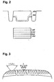
- the depth profile of the slats 14,15,16,17,18 is, as in Fig.2 is shown schematically on a profile block element shown by way of example with fins 100 and 200 formed.
- the fins are each formed with a substantially constant depth, which is reduced in the edge region of the profile block by 35 to 65%.
- the lamellae 100, which are closest to the profile block edge, are formed less deeply than the lamellae 200 in the interior of the profile block element.
- the edge area is between 3 and 6 mm thick
- the lamellae 14,15,16,17,18 are each formed with a sinusoidal course in the pad surface with the exception of the edge region of the respective tread block elements. Even along its depth extension, the course in sectional planes as described in patent application P 196 50 702.2 is parallel to the profile block element surface sinusoidal but with increasing depth with increasing phase shift.
- the phase shift in the depth direction takes place along a straight line which encloses an angle of> 0 ° with the radial. As in Fig. 3 is shown, takes place at two adjacent lamellae of a tread block element, the phase shift along two different lines with two opposite pitch directions.
- the helix angles of the two straight lines to the radial in one plane are alpha and beta.
- the lamellae of a tread block element are as described in the patent application P 196 50 702.2 alternately formed with a phase shift with the pitch angle alpha and with a phase shift to the pitch angle beta.
- the profile block elements are thereby crossed.
- Gamma is greater in the profile block elements 35 of the profile block row 5 than in the profile block elements 31, 32, 33, 34 of the profile block rows 1, 2, 3, 4.
- gamma is 40 ° in the tread block elements 35 and 20 ° in the tread block elements 31, 32, 33, 34.
- the width of the lamellae 14 to 18 is 0.3 to 0.6 mm, for example 0.4 mm.
- the width of the transverse grooves 9,10,12,13 is 3 to 8 mm.
- the width of the narrow transverse grooves 11 is 1 to 2 mm, for example, 1.1 mm.
- the tread block elements 33,34,35 additionally extending transversely to the slat direction ventilation lamellae 13 formed with a width of 0.8 to 1.3 mm, the adjacent lamellae with each other and the edge lamellae with the adjacent Connect grooves. Air pockets are thereby avoided.
- a rectilinear circumferential groove 22 having a width of 1 to 2 mm and a depth of 1.5 mm is additionally formed.
- the winter tire is a tubeless pneumatic vehicle tire of known radial type with steel or aramid reinforcements and, if necessary, with additional reinforcement known belt bandage of helically wound or juxtaposed bandage material with known suitable reinforcements - for example nylon.
Landscapes
- Engineering & Computer Science (AREA)
- Mechanical Engineering (AREA)
- Tires In General (AREA)
Description
- Die Erfindung betrifft ein Laufflächenprofil eines Winterreifens. An Winterreifen werden unterschiedliche einander widersprechende Anforderungen gestellt. So soll ein Winterreifen sowohl guten Griff auf Schnee und Eis als auch wie bei Sommerreifen gute Handlingeigenschaften gewährleisten. Diese Zielvorgaben erfordern sich widersprechende Maßnahmen in der Konstruktion des Winterreifens, so dass entweder ein Winterreifen mit guten Wintereigenschaften mit gutem Griff auf Eis und Schnee und vergleichsweise schlechtem Handling auf trockener Straße oder aber ein Sommerreifen mit gutem Handling auf trockener Straße, aber mit vergleichsweise schlechten Wintereigenschaften entsteht.
- Ein Winterreifen mit den Merkmalen des Oberbegriffs des Patentanspruchs 1 ist aus der
US 5,660,651 A bekannt. - Der Erfindung liegt die Aufgabe zugrunde ein Laufflächenprofil eines Winterreifens zu schaffen, das sowohl gute Wintereigenschaften mit gutem Griff auf Eis und Schnee als auch gutem Handling auf trockener Straße ermöglicht.
- Die Aufgabe wird erfindungsgemäß durch Ausbildung des Laufflächenprofils gemäß den Merkmalen des Anspruchs 1 gelöst. Durch die steifere Ausbildung der Profilblockelemente auf der zur Fahrzeugaußenseite weisenden Seite des Laufflächenprofils ist die für das Handling gewünschte Steifigkeit genau in dem für das Handling wichtigen Reifenseite (Handlingseite) und somit gutes Handling auf trockener Straße gewährleistet. In dem für das Handling weniger wichtigen axialen Laufflächenbereich (Winterseite) ist die für guten Griff auf Schnee und Eis wichtige geringe Steifigkeit der Profilblöcke und somit guter Wintergriff gewährleistet.
- Durch die Ausbildung gemäß den Merkmalen des Anspruchs 9 wird gerade auf der Winterseite eine besonders hohe Zahl von Traktionskanten geschaffen, wobei die Vielzahl der Lamellen, die für den Strukturfaktor verantwortlich sind, die Profilblöcke in dieser Winterseite noch weicher machen. Die Handlingseite ist durch die geringere Zahl der die Traktionskanten erzeugenden Lamellen steifer. Der Strukturfaktor in Umfangsrichtung ist die Summe der in Umfangsrichtung projezierten Profilblockkanten und Lamellen. Der Strukturfaktor quer zur Umfangsrichtung ist die Summe der quer zur Umfangsrichtung projezierten Profilblockkanten und Lamellen.
- Durch die Ausbildung gemäß den Merkmalen des Anspruchs 10 werden auf der Winterseite mehr und kleinere Profilelemente als auf der Handlingseite und somit noch mehr wintergrifferzeugende Profilkanten geschaffen. Auf der Handlingseite ist auch durch diese Maßnahme steifer ausgebildet.
- Die freie Durchsicht einer Umfangsnut ist ein Maß für den Eisgriff- und Schneegriff.
- Durch die Merkmale des Anspruchs 4 werden die Profilblockelemente außen mit einer harten, abriebreduzierenden Schale und innen mit einem weichen, die Wintereigenschaften verbessernden Kern ausgebildet.
- Die Ausbildung gemäß den Merkmalen des Anspruchs 5 ermöglicht eine besonders hohe wirkende Kantenlänge in den Profilblockelementen. Die Ausbildung gemäß den Merkmalen von Anspruch 6 ermöglicht eine besonders hohe wirkende Kantenlänge in den Profilblockelementen der Winterseite und weniger große wirkende Kantenlänge und somit höhere Steifigkeit in den Profilblockelementen der Handlingseite.
- Die Ausbildung gemäß den Merkmalen von Anspruch 11 ermöglicht ein sicheres Abfließen von Wasser durch die Profilrillen und sichert somit gute Aquaplaningeigenschaften.
- Die Erfindung wird im folgenden anhand der in den
Figuren 1 bis 5 dargestellten Ausführungsbeispiele näher erläutert. Hierin zeigen - Fig. 1
- Ausschnitt eines Laufflächenprofils in Draufsicht,
- Fig. 2
- Darstellung der Lamelle gemäß Schnitt II-II von
Fig.1 zur Erläuterung des Tiefenverlaufs, - Fig. 3
- Darstellung benachbarter Lamellen zur Erläuterung der Verschränkung,
- Fig. 4
- Darstellung zur Erläuterung des Querrillenversatzes,
- Fig. 5
- Darstellung zur Erläuterung der wirkenden Lamellenlänge eines Profilklotzes.
-
Fig. 1 zeigt einen Umfangsabschnitt eines Laufflächenprofils eines schlauchlosen Winterreifens mit fünf in axialer Richtung nebeneinander angeordneten Profilblockreihen 1,2,3,4 und 5. Die beiden außenliegenden Profilblockreihen 1,5 sind Schulterblockreihen. Die benachbarten Profilblockreihen 1 und 2 bzw 2 und 3 bzw 4 und 5 sind jeweils durch eine Umfangsrille 6 bzw 7 bzw 8 axial voneinander getrennt. Die in Umfangsrichtung hintereinander angeordneten Profilblockelemente 31 der Schulterblockreihe1 sind jeweils durch Querrillen 9 voneinander beabstandet. Die in Umfangsrichtung hintereinander angeordneten Profilblockelemente 35 der Schulterblockreihe 5 sind jeweils durch Querrillen 13 voneinander beabstandet. Die in Umfangsrichtung hintereinander angeordneten Profilblockelemente 32 der Profilblockreihe 2 sind jeweils durch Querrillen 10 voneinander beabstandet. Die in Umfangsrichtung hintereinander angeordneten Profilblockelemente 33 der Profilblockreihe 3 sind jeweils durch Querrillen 11 voneinander beabstandet. Die in Umfangsrichtung hintereinander angeordneten Profilblockelemente 34 der Profilblockreihe 4 sind jeweils durch Querrillen 12 voneinander beabstandet. Die Querrillen11 und 12 trennen auch die Profilblockreihen 3 und 4 in axialer Richtung. - Die Profilblockelemente 31, 32 , 33, 34 und 35 der Profilblockreihen 1,2,3,4 und 5 sind jeweils mit sinusförmig ausgebildeten Lamellen (Feineinschnitten) 14, 15, 16, 17 und 18 ausgebildet.
- In
Fig.1 ist die Breite der Bodenaufstandsfläche TA , die sich von Schulterprofilblockreihe zu Schulterprofilblockreihe erstreckt, eingezeichnet. Das Profil ist axial in zwei funktional unterschiedliche Bereiche A und I aufgeteilt. Der Bereich A, der sich von der im Betriebszustand eines Fahrzeugrades am Pkw zur Fahrzeugaußenseite weisenden Schulter bis zur Umfangsrille 7 erstreckt, ist konstruktiv speziell für gute Handlingeigenschaften ausgebildet und erstreckt sich axial über 25 und 75 % der Bodenaufstandsfläche, inFig. 1 über 40 % der Bodenaufstandstandsfläche. Der Bereich I, der sich von der im Betriebszustand eines Fahrzeugrades am Pkw zur Fahrzeuginnenseite weisenden Schulter bis zur Umfangsrille 7 erstreckt, ist konstruktiv speziell für gute Wintergriffeigenschaften ausgebildet. - Die beiden Umfangsrillen 6 und 7 sind sind geradlinig in Umfangsrichtung verlaufend mit gleichbleibender Breite ausgebildet. Sie gewährt guten Wasserablauf. Der freie Nutquerschnitt in Umfangsrichtung entspricht der Breite der Umfangsrille. Die Umfangsrille 8 ist in Umfangsrichtung verlaufend ausgebildet, wobei der Abstand zwischen den benachbarten Profilblockelementen 34 und 35 und somit die Breite im wesentlichen gleich bleibt und der Breite der Umfangsrillen 6 und 7 entspricht. Die Profilblockelemente 34 und 35 reichen mit ihren schräg zur Umfangsrichtung verlaufenden, die Umfangsrille 8 begrenzenden Seiten soweit in die Umfangsrille 8 hinein, dass der freie Nutquerschnitt in Umfangsrichtung (Projektion in Umfangsrichtung) deutlich kleiner als der freie Nutquerschnitt der Umfangsrillen 6 und 7 ist. Der freie Nutquerschnitt ist ein Maß für die in einer Nut vorhandenen Kanten und somit für den Eis- und Schneegriff im Bereich dieser Nut. Je niederer der freie Nutquerschnitt ist desto besser ist der Eis- und Schneegriff. Die Profilblockelemente 33 und 34 der Profilblockreihen 3 und 4 sind so ausgebildet, dass sie in axial in die jeweils benachbarte Profilblockreihe hinein erstrecken. Zwischen diesen Profilblockreihen gibt es keinen freien Nutquerschnitt in Umfangsrichtung. Der freie Nutquerschnitt in Umfangsrichtung ist somit im Bereich 1 kleiner als im Bereich A.
- Die Pitchzahl der Profilblockreihen im Bereich I ist höher als die Pitchzahl im Bereich A. Beispielsweise ist die Pitchzahl im Bereich 163 und im Bereich A 59. Auf diese Weise sind im Bereich I über den Umfang verteilt mehr und kürzere Profilblockelemente ausgebildet als im Bereich A. Im Bereich I sind somit mehr Kanten ausgebildet als im Bereich A. Die Profilblöcke des Bereichs A sind größer und steifer ausgebildet als die des Bereichs 1. Die Querrille 10 und die Querrille 9 sind schräg verlaufend mit einem Steigungswinkel > 0° zur Axialrichtung und ausgehend von derMündung der Querrille 10 in die Umfangsrille 7 nach axial außen mit kontinuierlich abnehmender Steigung, d. h. mit abnehmendem Steigungswinkel zur Axialrichtung, ausgebildet. Im Bereich der Umfangsrille 6 sind die beiden Querrillen 10 und 9 zueinander in Umfangsrichtung soweit versetzt, dass sie in ihrer Verlängerung entsprechend dem Steigungsverlauf der Querrille 10 bzw 9 an einer Seitenwand eines Profilblockelementes 31 bzw 32 der jeweils anderen Profilblockreihe 1 bzw 2 enden.
- Die Querrille 11 ist schräg verlaufend mit einem Steigungswinkel > 0° zur Axialrichtung und ausgehend von der Umfangsrille 7 nach axial außen mit kontinuierlich zunehmender Steigung, d. h mit zunehmendem Steigungswinkel zur Axialrichtung, ausgebildet.
- Die Querrille 12 und die Querrille 13 sind schräg verlaufend mit einem Steigungswinkel < 0° zur Axialrichtung und ausgehend von der stumpfen Mündung der Querrille 12 in die Querrille 11 nach axial außen mit kontinuierlich abehmender negativer Steigung, d. h mit abnehmendem negativem Steigungswinkel zur Axialrichtung, ausgebildet. Im Bereich der Umfangsrille 8 sind die beiden Querrillen 12 und 13 zueinander in Umfangsrichtung soweit versetzt, dass sie in gleicher Umfangsposition in die Umfangsrille 8 münden. Hierdurch wird - wie in
Fig.4b dargestellt ist - der Wasserableitwiderstand gegenüber einer unversetzten Ausführung gemäßFig.4a .reduziert. - Die Profilblockelemente 31 bzw 35 der Schulterblockreihen 1 und 5 sind jeweils mit mehreren parallel zueinander und zu den jeweiligen Querrillen 9 bzw 13 ausgebildeten Lamellen 14 bzw 18 ausgebildet. Die Lamellen 14 bzw 18 erstrecken sich jeweils ausgehend von der benachbarten Umfangsrille 6 bzw 8 bis außerhalb der axialen Erstreckung der Bodenaufstandsfläche TA.
- Die Profilblockelemente 32 , 33 und 34 der Profilblockreihen 2,3 und 4 sind jeweils mit mehreren parallel zu einander ausgebildeten Lamellen 15, 16 und 17 ausgebildet, die sich über den jeweiligen gesamten Profilblock erstrecken und auf beiden Seiten jeweils in einer Umfangs- bzw Querrille münden.
- Die Lamellen 15, 16, 17 sind dabei, wie in
Figur 5 an einem zur Vereinfachung quadratischen Profilblockelement schematisch dargestellt, ausgebildet. Die Lamellen sind mit einem Winkel zwischen 70 und 110° zur Hauptdiagonalen ausgebildet, wie inFig.5b dargestellt. Die Gesamtlamellenlänge des Profilblockelementes ist hierdurch größer als bei Ausbildung der Lamellen mit einem 45° - Winkel zur Hauptdiagonalen, wie inFig.5a dargestellt ist. - Die Lamellen 14, 15, 16, 17, 18 sind in ihren jeweiligen Profilblockelementen jeweils so angeordnet, dass der Abstand zwischen den einzelnen benachbarten Lamellen innerhalb eines Profilblockelementes im wesentlichen gleich ist und dass der Rand des Profilblockelementes nebender außenliebenden Lamellen in senkrechter Richtung zur Lamellenausrichtung eine maximale Breite aufweist, die um 7 bis 15 %größer ist als die Breite der Abstände zwischen den Lamellen dieses Profilblockelementes.
- Der Tiefenverlauf der Lamellen 14,15,16,17,18 ist , wie in
Fig.2 an einem beispielhaft dargestellten Profilblockelement mit Lamellen 100 und 200 schematisch dargestellt ist, ausgebildet. Die Lamellen sind jeweils mit im wesentlichen konstanter Tiefe ausgebildet, die jedoch im Randbereich des Profilblocks um 35 bis 65 % reduziert ist. Die Lamellen 100,die dem Profilblockrand am Nächsten liegen sind weniger tief ausgebildet als die Lamellen 200 im innern des Profilblockelementes. - Der Randbereich ist zwischen 3 und 6 mm dick
- Die Lamellen sind 14,15,16,17,18 mit Ausnahme des Randbereichs der jeweiligen Profilblockelemente jeweils mit einem sinusförmigen Verlauf in der Klotzoberfläche ausgebildet. Auch entlang ihrer Tiefenerstreckung ist der Verlauf in Schnittebenen wie in der Patentanmeldung P 196 50 702.2 beschrieben parallel zur Profilblockelementoberfläche sinusförmig jedoch mit zunehmender Tiefe mit zunehmender Phasenverschiebung. Die Phasenverschiebung in Tiefenrichtung erfolgt entlang einer Geraden, die mit der Radialen einen Winkel >0° einschließt. Wie in
Fig. 3 dargestellt ist, findet bei zwei benachbarten Lamellen eines Profilblockelementes die Phasenverschiebung entlang zweier unterschiedlicher Geraden mit zwei entgegengesetzten Steigungsrichtungen statt. Die Steigungswinkel der beiden Geraden zur Radialen in einer Ebene sind Alpha und Beta. Die Lamellen eines Profilblockelementes sind wie in der Patentanmeldung P 196 50 702.2 beschrieben alternierend mit einer Phasenverschiebung mit dem Steigungswinkel Alpha und mit einer Phasenverschiebung um den Steigungswinkel Beta ausgebildet. Die Profilblockelemente werden hierdurch verschränkt. Der Summenwinkel Gamma = Alpha + Beta ist ein Maß für die Verschränkung. Gamma ist in den Profilblockelementen 35 der Profilblockreihe 5 größer als in den Profilblockelementen 31,32,33,34 der Profilblockreihen 1,2,3,4. Beispielsweise beträgt Gamma in den Profilblockelementen 35 40° und in den Profilblockelementen 31,32,33,34 20°. - Die Breite der Lamellen 14 bis 18 beträgt 0,3 bis 0,6 mm , beispielsweise 0,4 mm.
- Die Breite der Querrillen 9,10,12,13 beträgt 3 bis 8 mm.
Die Breite der schmalen Querrillen 11 beträgt 1 bis 2 mm, beispielsweise 1,1 mm. - Zur Entlüftung der Lamellen 16, 17, 18 sind in den Profilblockelementen 33,34,35 zusätzlich quer zur Lamellenrichtung verlaufende Entlüftungslamellen 13 mit einer Breite von 0,8 bis 1,3 mm ausgebildet, die die benachbarten Lamellen miteinander un die Randlamellen mit den angrenzenden Rillen verbinden. Lufteinschlüsse werden hierdurch vermieden.
- In der Profilblockreihe 2 ist zuätzlich eine geradlinige umfangsgerichtete Rille 22 mit 1 bis 2 mm Breite und mit 1,5 mm Tiefe ausgebildet.
- Der Winterreifen ist ein schlauchloser Fahrzeugluftreifen bekannter radialer Bauart mit Gürtel mit Festigkeitsträgern aus Stahl oder Aramid und - falls erforderlich mit zusätzlicher bekannter Gürtelbandage aus wendelförmig gewickeltem oder nebeneinander aufgelegtem Bandagematerial mit bekannten geeigneten Festigkeitsträgern - beispielsweise Nylon.
-
- 1
- Profilblockreihe
- 2
- Profilblockreihe
- 3
- Profilblockreihe
- 4
- Profilblockreihe
- 5
- Profilblockreihe
- 6
- Umfangsrille
- 7
- Umfangsrille
- 8
- Umfangsrille
- 9
- Querrille
- 10
- Querrille
- 11
- Querrille
- 12
- Querrille
- 13
- Querrille
- 14
- Lamelle
- 15
- Lamelle
- 16
- Lamelle
- 17
- Lamelle
- 18
- Lamelle
- 19
- Lamelle
- 20
- Lamelle
- 21
- Lamelle
- 22
- Umfangslamelle
- 31
- Profilblockelement
- 32
- Profilblockelement
- 33
- Profilblockelement
- 34
- Profilblockelement
- 35
- Profilblockelement
- 100
- Lamelle
- 200
- Lamelle
Claims (11)
- Laufflächenprofil eines Winterreifens für Fahrzeuge mit wenigstens zwei außerhalb der Fahrzeuglängsachse ausgebildeten Fahrzeugrädern- mit in axialer Richtung von Reifenschulter zu Reifenschulter verteilt angeordneten und durch Umfangsrillen (6,7,8) axial voneinander beabstandeten in Umfangsrichtung ausgerichteten Profilblockreihen (1 - 5),- bei dem eine erste Umfangsrille (7) das Laufflächenprofil in zwei funktional unterschiedlich ausgebildete Bereiche (A;I) aufteilt, die sich axial jeweils von der zugehörigen Reifenschulter bis zu dieser ersten Umfangsrille (7) erstrecken,- wobei die Profilblockelemente (31, 32) in dem axialen Bereich (A), der sich von dieser Umfangsrille (7) bis zur im Betriebszustand des Reifens am Fahrzeug zur Fahrzeugaußenseite weisenden Schulter erstreckt, mit einer höheren Querschubsteifigkeit ausgebildet sind als die Profilblockelemente (33, 34, 35) in dem axialen Bereich (1), der sich von dieser ersten Umfangsrille (7) bis zur im Betriebszustand des Reifens am Fahrzeug zur Fahrzeuginnenseite weisenden Schulter erstreckt, wobei sowohl in dem axialen Bereich (I) , der sich von dieser ersten Umfangsrille bis zur im Betriebszustand des Reifens am Fahrzeug zur Fahrzeuginnenseite weisenden Schulter erstreckt, als auch in dem axialen Bereich (A), der sich von dieser ersten Umfangsrille (7) bis zur im Betriebszustand des Reifens am Fahrzeug zur Fahrzeugaußenseite weisenden Schulter erstreckt, jeweils wenigstens eine weitere Umfangsrille (8;6) ausgebildet ist, die jeweils zwei Profilblockreihen (5, 4; 2, 1) voneinander trennt, wobei wenigstens im axialen Bereich (A) Profilblockreihen (1,2) aus in Umfangsrichtung hintereinander angeordneten und durch schräg verlaufende Querrillen (9, 10) voneinander beabstandeten Profilblockelementen (31, 32) ausgebildet sind, so dass die Profilblockelemente (31,32) mit schräg verlaufenden, die Profilblockelemente (31, 32) in Umfangsrichtung begrenzenden Querkanten ausgebildet sind, dadurch gekennzeichnet, dass die Querrillen (9; 10) im Bereich ihrer Mündung in die Umfangsrille (6) zueinander in Umfangsrichtung soweit versetzt sind, dass sie in ihrer Verlängerung entsprechend dem Steigungsverlauf der jeweiligen Querrille (9;10) an einer Seitenwand eines Profilblockelementes (31; 32) der jeweils anderen Profilblockreihe (1; 2) stumpf enden.
- Asymmetrisches Laufflächenprofil eines Winterreifens gemäß den Merkmalen des Anspruchs 1, dadurch gekennzeichnet, dass die Profilblockelemente (31, 32 , 33, 34, 35) der Profilblockreihen (1,2,3,4, 5) jeweils mit Lamellen (14, 15, 16, 17, 18) versehen sind, welche mit einem sinusförmigen Verlauf in der Profilblockelementoberfläche ausgebildet sind.
- Asymmetrisches Laufflächenprofil eines Winterreifens gemäß den Merkmalen von einem oder mehreren der vorangegangenen Ansprüche, dadurch gekennzeichnet, dass die Profilblockelemente (32 , 33, 34) der Profilblockreihen (2,3,4) jeweils mit mehreren parallel zu einander ausgebildeten Lamellen (15, 16, 17) ausgebildet sind, die sich über den jeweiligen gesamten Profilblock erstrecken und auf beiden Seiten jeweils in einer Umfangsrille (6,7,8) und/oder einer Querrille (9 - 13) münden.
- Asymmetrisches Laufflächenprofil eines Winterreifens gemäß den Merkmalen von einem oder mehreren der vorangegangenen Ansprüche,- wobei Profilblockelemente (33,34,35) der Profilblockreihen (3,4,5) in dem axialen Bereich (I), der sich von dieser ersten Umfangsrille (7) bis zur im Betriebszustand des Reifens am Fahrzeug zur Fahrzeuginnenseite weisenden Schulter erstreckt, mit mehreren voneinander beabstandeten, sich über das Profilblockelement (33,34,35) erstreckenden Lamellen (16 -21) ausgebildet sind,- wobei der Tiefenverlauf der Lamellen eines Profilblockelementes durch das Profilblockelement mit einer Tiefe am Rand des Profilblockelementes - insbesondere 10 bis 20 % - kleiner als zwischen den Rändern im Innern des Profilblockelements ausgebildet ist.
- Asymmetrisches Laufflächenprofil eines Winterreifens gemäß den Merkmalen von einem oder mehreren der vorangegangenen Ansprüche,- bei dem zumindest eine Profilblockreihe aus in Umfangsrichtung hintereinander angeordneten und durch schräg verlaufende Querrillen voneinander beabstandete Profilblockelemente ausgebildet sind, so dass die Profilblockelemente mit schräg verlaufenden, die Profilblockeiemente in Umfangsrichtung begrenzenden Querkanten ausgebildet sind, und- bei dem die Profilblockelemente dieser Profilblockreihe in axialer Richtung mit seitlich die Profilblockelemente begrenzenden Längskanten ausgebildet sind,- wobei die Profilblockelement der Profilblockreihe mit mehreren voneinander beabstandeten, sich über das Profilblockelement erstreckenden Lamellen ausgebildet sind, wobei die Lamellen in ihrer Ausrichtung einen Winkel zwischen 80 und 110° zu der längeren Diagonalen des durch die Querkanten und die Längskanten gebildeten Trapezes einschließen.
- Asymmetrisches Laufflächenprofil eines Winterreifens gemäß den Merkmalen von einem oder mehreren der vorangegangenen Ansprüche,- bei dem die Profilblockreihen in den Reifenschultern und wenigstens eine weitere Profilblockreihe ausgebildet ist, die zwischen den Reifenschultern angeordnet ist, wobei die Profilblockreihen jeweils aus in Umfangsrichtung hintereinander angeordneten und durch schräg verlaufende Querrillen voneinander beabstandete Profilblockelemente ausgebildet sind, so dass die Profilblockelemente mit schräg verlaufenden, die Profilblockelemente in Umfangsrichtung begrenzenden Querkanten ausgebildet sind,- bei dem die Profilblockelemente der Profilblockreihen in axialer Richtung mit seitlich die Profilblockelemente begrenzenden Längskanten ausgebildet sind,- wobei die Profilblockelement der Profilblockreihen mit mehreren voneinander beabstandeten, sich über das Profilblockelement erstreckenden Lamellen ausgebildet sind,- wobei die Lamellen der Schulterprofilblockreihen in ihrer Ausrichtung parallel zu den die Profilblockelemente in der jeweiligen Schulterprofilblockreihe in Umfangsrichtung begrenzenden Querrille ausgebildet sind, und- wobei die Lamellen der zwischen den Schulterprofilblockreihen ausgebildeten Profilblockreihe in ihrer Ausrichtung einen Winkel zwischen 80 und 110° zu der Hauptdiagonalen des durch die Querkanten und die Längskanten gebildeten Trapezes einschließen.
- Asymmetrisches Laufflächenprofil eines Winterreifens gemäß den Merkmalen von einem oder mehreren der vorangegangenen Ansprüche, dadurch gekennzeichnet, dass von Umfangsrillen (7,8) begrenzte Profilblockelemente (33,34) zueinander durch Querrillen (11,12) begrenzt sind, wobei die Querrillen (11) schräg verlaufen und eine Breite von 1 bis 2 mm aufweisen, und wobei die Querrillen (12) schräg verlaufen und eine Breite von 3 bis 8 mm aufweisen.
- Asymmetrisches Laufflächenprofil eines Winterreifens gemäß den Merkmalen von einem oder mehreren der vorangegangenen Ansprüche, dadurch gekennzeichet, dass die Profilblockelemente (33,34) der Profilblockreihen (3,4) so ausgebildet sind, dass sie sich axial in die jeweils benachbarte Profilblockreihe (3;4) hinein erstrecken, so dass zwischen diesen Profilblockreihen (3,4) kein freier Nutquerschnitt in Umfangsrichtung besteht.
- Asymmetrisches Laufflächenprofil eines Winterreifens gemäß den Merkmalen des Anspruchs 1,- wobei sowohl der Strukturfakror längs in Umfangsrichtung als auch der Strukturfaktor quer zur Umfangsrichtung in den Profilblockelementen in dem axialen Bereich, der sich von dieser Umfangsrille bis zur im Betriebszustand des Reifens am Fahrzeug zur Fahrzeuginnenseite weisenden Schulter erstreckt, zwischen 10 und 50 % höher ist als in den Profilblockelementen in dem axialen Bereich, der sich von dieser ersten Umfangsrille bis zur im Betriebszustand des Reifens am Fahrzeug zur Fahrzeugaußenseite weisenden Schulter erstreckt.
- Asymmetrisches Laufflächenprofil eines Winterreifens gemäß den Merkmalen des Anspruchs 1 oder 2,- bei dem die Pitchzahl in dem axialen Bereich, der sich von dieser ersten Umfangsrille bis zur im Betriebszustand des Reifens am Fahrzeug zur Fahrzeuginnenseite weisenden Schulter erstreckt, größer ist als in dem axialen Bereich, der sich von dieser ersten Umfangsrille bis zur im Betriebszustand des Reifens am Fahrzeug zur Fahrzeugaußenseite weisenden Schulter erstreckt.
- Asymmetrisches Laufflächenprofil eines Winterreifens gemäß den Merkmalen von einem oder mehreren der vorangegangenen Ansprüche,- wobei in dem axialen Bereich, der sich von dieser ersten Umfangsrille bis zur im Betriebszustand des Reifens am Fahrzeug zur Fahrzeuginnenseite weisenden Schulter erstreckt, eine weitere Profilblockreihe ausgebildet ist, die durch eine Umfangsrille bzw. Umfangsnut von der Profilblockreihe, die in der im Betriebszustand des Reifens am Fahrzeug zur Fahrzeuginnenseite weisenden Schulter, ausgebildet ist betrennt ist,- wobei diese beiden benachbarten Profilblockreihen jeweils aus in Umfangsrichtung hintereinander angeordneten und durch schräg verlaufende Querrillen voneinander beabstandete Profilblockelemente ausgebildet sind, so dass die Profilblockelemente mit schräg verlaufenden, die Profilblockelemente in Umfangsrichtung-begrenzenden Querkanten ausgebildet sind, wobei sich die Querrillen über beide Profilblockreihen ausgehend von der Reifenschulter nach axial innen hin unter stetiger Steigung erstrecken, wobei die Querrillen beim Übergang durch die Umfangsrille in Umfangsrichtung derart versetzt zu einander ausgebildet sind, dass das zur Umfangsrille weisende Ende der Querrille in der Schulterblockreihe die gleiche Umfangsposition wie das zur Umfangsrille weisende Ende der Querrille in der weiteren Profilblockreihe einnimmt.
Priority Applications (1)
| Application Number | Priority Date | Filing Date | Title |
|---|---|---|---|
| DE29825135U DE29825135U1 (de) | 1997-12-04 | 1998-11-23 | Laufflächenprofil eines Winterreifens |
Applications Claiming Priority (3)
| Application Number | Priority Date | Filing Date | Title |
|---|---|---|---|
| DE19753819A DE19753819B4 (de) | 1997-12-04 | 1997-12-04 | Laufflächenprofil eines Winterreifens |
| DE19753819 | 1997-12-04 | ||
| EP98122227A EP0921020B1 (de) | 1997-12-04 | 1998-11-23 | Laufflächenprofil eines Winterreifens |
Related Parent Applications (1)
| Application Number | Title | Priority Date | Filing Date |
|---|---|---|---|
| EP98122227A Division EP0921020B1 (de) | 1997-12-04 | 1998-11-23 | Laufflächenprofil eines Winterreifens |
Publications (2)
| Publication Number | Publication Date |
|---|---|
| EP1529660A1 EP1529660A1 (de) | 2005-05-11 |
| EP1529660B1 true EP1529660B1 (de) | 2008-11-05 |
Family
ID=7850737
Family Applications (2)
| Application Number | Title | Priority Date | Filing Date |
|---|---|---|---|
| EP98122227A Expired - Lifetime EP0921020B1 (de) | 1997-12-04 | 1998-11-23 | Laufflächenprofil eines Winterreifens |
| EP05001621A Expired - Lifetime EP1529660B1 (de) | 1997-12-04 | 1998-11-23 | Laufflächenprofil eines Winterreifens |
Family Applications Before (1)
| Application Number | Title | Priority Date | Filing Date |
|---|---|---|---|
| EP98122227A Expired - Lifetime EP0921020B1 (de) | 1997-12-04 | 1998-11-23 | Laufflächenprofil eines Winterreifens |
Country Status (6)
| Country | Link |
|---|---|
| US (1) | US6619352B2 (de) |
| EP (2) | EP0921020B1 (de) |
| JP (1) | JPH11321240A (de) |
| AT (2) | ATE330799T1 (de) |
| CA (1) | CA2255254A1 (de) |
| DE (3) | DE19753819B4 (de) |
Families Citing this family (58)
| Publication number | Priority date | Publication date | Assignee | Title |
|---|---|---|---|---|
| DE20216992U1 (de) | 2002-11-04 | 2003-01-16 | Goodyear Dunlop Tires Germany GmbH, 63450 Hanau | Fahrzeugluftreifen, insbesondere Sommerreifen für Personenkraftwagen |
| USD490769S1 (en) | 2002-12-10 | 2004-06-01 | Continental Aktiengesellschaft | Tire tread |
| DE10257487A1 (de) * | 2002-12-10 | 2004-07-01 | Continental Aktiengesellschaft | Fahrzeugluftreifen zum Einsatz unter winterlichen Fahrbedingungen |
| CA2506071A1 (en) * | 2002-12-19 | 2004-07-08 | Pirelli Pneumatici S.P.A. | Tread pattern for winter tires |
| DE10312488A1 (de) * | 2003-03-20 | 2004-09-30 | Continental Aktiengesellschaft | Fahrzeugreifen, insbesondere Winterreifen mit einem Laufstreifenprofil |
| DE10352145A1 (de) * | 2003-11-04 | 2005-06-09 | Continental Aktiengesellschaft | Fahrzeugluftreifen |
| DE10352149A1 (de) | 2003-11-04 | 2005-06-02 | Continental Aktiengesellschaft | Fahrzeugluftreifen |
| USD502682S1 (en) | 2004-02-23 | 2005-03-08 | Continental Tire North America, Inc. | Tire |
| US7207364B2 (en) * | 2004-02-23 | 2007-04-24 | Continental Tire North America, Inc. | Radial tire with tread pattern having four or five circumferential ribs |
| USD510064S1 (en) | 2004-02-23 | 2005-09-27 | Continental Tire North America, Inc. | Tire |
| USD504386S1 (en) | 2004-05-21 | 2005-04-26 | Bridgestone/Firestone North American Tire, Llc | Tire tread |
| US7213816B2 (en) * | 2004-06-23 | 2007-05-08 | Wal-Mart Stores, Inc. | Cart for stocking inventory and methods for making same |
| USD525187S1 (en) * | 2004-06-30 | 2006-07-18 | Kumho Tire Co., Inc. | Tire for a car |
| EP1619048B1 (de) | 2004-07-15 | 2013-09-11 | Continental Reifen Deutschland GmbH | Fahrzeugluftreifen |
| JP4568099B2 (ja) * | 2004-11-30 | 2010-10-27 | 株式会社ブリヂストン | 空気入りタイヤ |
| US20060118220A1 (en) * | 2004-12-06 | 2006-06-08 | The Goodyear Tire & Rubber Company | Pneumatic tire with elliptical shoulder |
| JP4656989B2 (ja) * | 2005-04-12 | 2011-03-23 | 株式会社ブリヂストン | 空気入りタイヤ |
| JP4215751B2 (ja) * | 2005-07-06 | 2009-01-28 | 横浜ゴム株式会社 | 空気入りタイヤ |
| JP4764085B2 (ja) * | 2005-07-22 | 2011-08-31 | 株式会社ブリヂストン | 空気入りタイヤ |
| USD524237S1 (en) * | 2005-09-08 | 2006-07-04 | The Goodyear Tire & Rubber Company | Tire tread |
| JP5114890B2 (ja) * | 2006-07-28 | 2013-01-09 | 横浜ゴム株式会社 | 空気入りタイヤ |
| EP2058144B1 (de) * | 2006-08-29 | 2010-12-01 | The Yokohama Rubber Co., Ltd. | Luftreifen |
| JP4899787B2 (ja) * | 2006-10-26 | 2012-03-21 | 横浜ゴム株式会社 | 空気入りタイヤ |
| JP4145337B2 (ja) | 2007-01-17 | 2008-09-03 | 横浜ゴム株式会社 | 空気入りタイヤ |
| USD566037S1 (en) * | 2007-02-05 | 2008-04-08 | Nokian Tyres Plc | Tyre |
| JP5161478B2 (ja) * | 2007-04-19 | 2013-03-13 | 住友ゴム工業株式会社 | 空気入りタイヤ |
| JP5092593B2 (ja) * | 2007-07-06 | 2012-12-05 | 横浜ゴム株式会社 | 空気入りタイヤ |
| JP4496254B2 (ja) * | 2008-01-15 | 2010-07-07 | 東洋ゴム工業株式会社 | 空気入りタイヤ |
| USD593932S1 (en) * | 2008-03-07 | 2009-06-09 | Continental Aktiengesellschaft | Tire tread |
| EP2311658B1 (de) | 2008-07-10 | 2012-12-05 | Bridgestone Corporation | Spikeloser reifen |
| AU325571S (en) * | 2008-12-03 | 2009-04-03 | Continental Reifen Deutschland Gmbh | Tyre |
| JP5603563B2 (ja) * | 2009-04-24 | 2014-10-08 | 株式会社ブリヂストン | タイヤ |
| DE102009059169A1 (de) | 2009-12-16 | 2011-06-22 | Continental Reifen Deutschland GmbH, 30165 | Fahrzeugluftreifen |
| DE102010000210A1 (de) * | 2010-01-26 | 2011-07-28 | Continental Reifen Deutschland GmbH, 30165 | Fahrzeugluftreifen |
| JP5461233B2 (ja) * | 2010-02-26 | 2014-04-02 | 株式会社ブリヂストン | 空気入りタイヤ |
| CN102770286B (zh) * | 2010-02-26 | 2015-12-16 | 株式会社普利司通 | 充气轮胎 |
| JP5419752B2 (ja) * | 2010-02-26 | 2014-02-19 | 株式会社ブリヂストン | 空気入りタイヤ |
| CA137175S (en) * | 2010-05-18 | 2011-09-28 | Continental Reifen Deutschland Gmbh | Tire |
| CA140299S (fr) * | 2010-11-29 | 2011-11-22 | Société de Technologie Michelin | Pneumatique |
| USD644983S1 (en) * | 2011-03-30 | 2011-09-13 | Continental Reifen Deutschland Gmbh | Tire tread for a vehicle tire |
| USD644594S1 (en) * | 2011-03-30 | 2011-09-06 | Continental Reifen Deutschland Gmbh | Tire tread for a vehicle tire |
| JP5480868B2 (ja) | 2011-10-07 | 2014-04-23 | 住友ゴム工業株式会社 | 空気入りタイヤ |
| JP5387659B2 (ja) | 2011-11-14 | 2014-01-15 | 横浜ゴム株式会社 | 空気入りタイヤ |
| JP2013249018A (ja) * | 2012-06-01 | 2013-12-12 | Yokohama Rubber Co Ltd:The | 空気入りタイヤ |
| CN104936795B (zh) * | 2013-01-28 | 2018-11-30 | 倍耐力轮胎股份公司 | 用于提高对轮胎的抓地能力的控制的方法以及根据该方法获得的轮胎 |
| FR3014750B1 (fr) * | 2013-12-17 | 2017-02-24 | Michelin & Cie | Bande de roulement comprenant des pavés et de fines rainures sur les pavés |
| CN105873775B (zh) * | 2013-12-23 | 2018-09-04 | 倍耐力轮胎股份公司 | 用于车辆车轮的具有改进的胎面花纹的轮胎 |
| EP3192673B1 (de) * | 2014-09-11 | 2019-04-03 | Bridgestone Corporation | Luftreifen |
| CN105216552B (zh) * | 2015-10-20 | 2017-05-10 | 特拓(青岛)轮胎技术有限公司 | 一种全天候四季轮胎胎面结构 |
| FR3044967B1 (fr) * | 2015-12-15 | 2017-12-22 | Michelin & Cie | Sommet de pneumatique pour vehicule lourd de type genie civil |
| JP6711172B2 (ja) * | 2016-06-27 | 2020-06-17 | 住友ゴム工業株式会社 | タイヤ |
| JP6769181B2 (ja) * | 2016-08-31 | 2020-10-14 | 住友ゴム工業株式会社 | タイヤ |
| JP7590176B2 (ja) * | 2020-12-21 | 2024-11-26 | Toyo Tire株式会社 | 空気入りタイヤ |
| US12420591B2 (en) * | 2021-05-05 | 2025-09-23 | The Goodyear Tire & Rubber Company | Tire tread |
| JP7694177B2 (ja) * | 2021-06-15 | 2025-06-18 | 住友ゴム工業株式会社 | タイヤ及びタイヤと車両との組合せ体 |
| USD986811S1 (en) | 2021-08-16 | 2023-05-23 | Bridgestone Americas Tire Operations, Llc | Tire |
| USD986810S1 (en) | 2021-08-16 | 2023-05-23 | Bridgestone Americas Tire Operations, Llc | Tire |
| USD1050004S1 (en) | 2022-12-06 | 2024-11-05 | Bridgestone Americas Tire Operations, Llc | Tire |
Family Cites Families (27)
| Publication number | Priority date | Publication date | Assignee | Title |
|---|---|---|---|---|
| FR791250A (fr) * | 1935-06-13 | 1935-12-06 | Michelin & Cie | Perfectionnement à la surface de roulement des pneumatiques |
| DE1886124U (de) * | 1963-03-02 | 1964-01-16 | Willy Ellenrieder | Winter-allwetter-kraftfahrzeugreifen. |
| DE1505097A1 (de) * | 1963-07-19 | 1969-02-27 | Metzeler Ag | Kraftfahrzeugluftreifen mit ueber die ganze Breite der Laufflaeche unregelmaessigem Profil |
| FR2457185A1 (fr) * | 1979-05-23 | 1980-12-19 | Kleber Colombes | Pneumatique neige |
| DE3130574A1 (de) * | 1981-08-01 | 1983-02-17 | Bayer Ag, 5090 Leverkusen | Reifen mit asymmetrischem laufflaechenprofil |
| DE3130675A1 (de) * | 1981-08-03 | 1983-02-17 | Desowag-Bayer Holzschutz GmbH, 4000 Düsseldorf | Holzschutzmittelkonzentrat und daraus hergestelltes mittel zum konservieren von holz und holzwerkstoffen |
| DE3324649A1 (de) * | 1983-07-08 | 1985-01-31 | Continental Gummi-Werke Ag, 3000 Hannover | Fahrzeugluftreifen |
| US4546808A (en) * | 1984-01-06 | 1985-10-15 | The Goodyear Tire & Rubber Company | Pneumatic tire |
| US4815511A (en) * | 1986-03-18 | 1989-03-28 | The Goodyear Tire & Rubber Company | All-season high-performance radial-ply passenger pneumatic tire |
| US4702292A (en) * | 1986-03-18 | 1987-10-27 | The Goodyear Tire & Rubber Company | High performance all-season tire tread |
| JP2639449B2 (ja) * | 1986-11-07 | 1997-08-13 | 株式会社 ブリヂストン | 空気入りラジアルタイヤ |
| JP2514780Y2 (ja) * | 1987-02-20 | 1996-10-23 | 株式会社ブリヂストン | 空気入りタイヤ |
| JPS6452507A (en) * | 1987-05-08 | 1989-02-28 | Bridgestone Corp | Pneumatic tire pair |
| US4913208A (en) * | 1988-01-21 | 1990-04-03 | The Goodyear Tire & Rubber Company | Pneumatic radial-ply tire having block pattern tread |
| JPH0657485B2 (ja) * | 1989-03-27 | 1994-08-03 | 株式会社ブリヂストン | ラジアルタイヤ対 |
| AT401160B (de) * | 1991-05-21 | 1996-07-25 | Semperit Ag | Luftreifen mit einer lauffläche |
| US5360043A (en) * | 1991-07-26 | 1994-11-01 | The Goodyear Tire & Rubber Company | Asymmetric tread for a tire |
| JPH05178014A (ja) * | 1991-12-26 | 1993-07-20 | Yokohama Rubber Co Ltd:The | 空気入りタイヤ |
| AT400694B (de) * | 1992-04-03 | 1996-02-26 | Semperit Ag | Fahrzeugreifen |
| JPH06106916A (ja) * | 1992-09-30 | 1994-04-19 | Bridgestone Corp | 空気入りタイヤ |
| JPH06143941A (ja) * | 1992-11-05 | 1994-05-24 | Yokohama Rubber Co Ltd:The | 空気入りタイヤ |
| JPH07186622A (ja) * | 1993-12-27 | 1995-07-25 | Yokohama Rubber Co Ltd:The | 空気入りラジアルタイヤ |
| AT402178B (de) * | 1994-02-25 | 1997-02-25 | Semperit Ag | Laufstreifen für einen fahrzeugluftreifen |
| DE4427895A1 (de) * | 1994-08-08 | 1996-02-15 | Continental Ag | Fahrzeugreifen mit einer Lauffläche mit im wesentlichen axial verlaufenden Einschnitten |
| AT404341B (de) * | 1996-02-12 | 1998-10-27 | Semperit Ag | Fahrzeugluftreifen |
| DE19650702A1 (de) * | 1996-12-06 | 1998-06-10 | Continental Ag | Fahrzeugreifen mit einer Lauffläche mit im wesentlichen axial verlaufenden Einschnitten |
| JP3177466B2 (ja) * | 1997-02-06 | 2001-06-18 | 住友ゴム工業株式会社 | 空気入りタイヤ |
-
1997
- 1997-12-04 DE DE19753819A patent/DE19753819B4/de not_active Expired - Lifetime
-
1998
- 1998-11-23 EP EP98122227A patent/EP0921020B1/de not_active Expired - Lifetime
- 1998-11-23 AT AT98122227T patent/ATE330799T1/de not_active IP Right Cessation
- 1998-11-23 AT AT05001621T patent/ATE413290T1/de active
- 1998-11-23 DE DE59814317T patent/DE59814317D1/de not_active Expired - Lifetime
- 1998-11-23 EP EP05001621A patent/EP1529660B1/de not_active Expired - Lifetime
- 1998-11-23 DE DE59813613T patent/DE59813613D1/de not_active Expired - Lifetime
- 1998-12-03 US US09/204,291 patent/US6619352B2/en not_active Expired - Fee Related
- 1998-12-03 JP JP10344417A patent/JPH11321240A/ja not_active Withdrawn
- 1998-12-03 CA CA002255254A patent/CA2255254A1/en not_active Abandoned
Also Published As
| Publication number | Publication date |
|---|---|
| DE19753819A1 (de) | 1999-06-17 |
| EP0921020A3 (de) | 2001-03-07 |
| CA2255254A1 (en) | 1999-06-04 |
| EP1529660A1 (de) | 2005-05-11 |
| US20010035244A1 (en) | 2001-11-01 |
| DE59813613D1 (de) | 2006-08-03 |
| ATE330799T1 (de) | 2006-07-15 |
| EP0921020B1 (de) | 2006-06-21 |
| DE59814317D1 (de) | 2008-12-18 |
| EP0921020A2 (de) | 1999-06-09 |
| ATE413290T1 (de) | 2008-11-15 |
| JPH11321240A (ja) | 1999-11-24 |
| US6619352B2 (en) | 2003-09-16 |
| DE19753819B4 (de) | 2004-04-01 |
Similar Documents
| Publication | Publication Date | Title |
|---|---|---|
| EP1529660B1 (de) | Laufflächenprofil eines Winterreifens | |
| EP2349746B1 (de) | Fahrzeugluftreifen | |
| EP2222481A1 (de) | Fahrzeugluftreifen | |
| EP3300926B1 (de) | Fahrzeugluftreifen | |
| DE102007051645A1 (de) | Fahrzeugluftreifen | |
| EP3256335B1 (de) | Fahrzeugluftreifen | |
| EP4577416A1 (de) | Fahrzeugluftreifen | |
| EP0588781B1 (de) | Fahrzeugreifen | |
| EP3750723B1 (de) | Fahrzeugluftreifen | |
| EP3100872B1 (de) | Fahrzeugluftreifen | |
| EP3224060B1 (de) | Fahrzeugluftreifen | |
| EP3441241A1 (de) | Fahrzeugluftreifen | |
| EP2556971B1 (de) | Fahrzeugluftreifen | |
| EP3300925B1 (de) | Fahrzeugluftreifen | |
| EP2138329A1 (de) | Laufflächenprofil für einen Fahrzeugluftreifen | |
| DE29825135U1 (de) | Laufflächenprofil eines Winterreifens | |
| EP4514627A1 (de) | Fahrzeugreifen | |
| EP4577417A1 (de) | Fahrzeugluftreifen | |
| EP3663105B1 (de) | Fahrzeugreifen | |
| WO2022253375A1 (de) | Fahrzeugluftreifen | |
| EP2138328A1 (de) | Fahrzeugluftreifen | |
| EP4360913B1 (de) | Fahrzeugluftreifen | |
| EP4003760A1 (de) | Fahrzeugluftreifen | |
| EP4514631B1 (de) | Fahrzeugluftreifen | |
| EP4244079B1 (de) | Fahrzeugluftreifen |
Legal Events
| Date | Code | Title | Description |
|---|---|---|---|
| PUAI | Public reference made under article 153(3) epc to a published international application that has entered the european phase |
Free format text: ORIGINAL CODE: 0009012 |
|
| AC | Divisional application: reference to earlier application |
Ref document number: 0921020 Country of ref document: EP Kind code of ref document: P |
|
| AK | Designated contracting states |
Kind code of ref document: A1 Designated state(s): AT CH DE FI FR GB IT LI SE |
|
| 17P | Request for examination filed |
Effective date: 20051111 |
|
| AKX | Designation fees paid |
Designated state(s): AT CH DE FI FR GB IT LI SE |
|
| GRAP | Despatch of communication of intention to grant a patent |
Free format text: ORIGINAL CODE: EPIDOSNIGR1 |
|
| RIC1 | Information provided on ipc code assigned before grant |
Ipc: B60C 11/12 20060101ALI20060725BHEP Ipc: B60C 11/03 20060101AFI20060725BHEP Ipc: B60C 11/11 20060101ALI20060725BHEP |
|
| GRAS | Grant fee paid |
Free format text: ORIGINAL CODE: EPIDOSNIGR3 |
|
| GRAA | (expected) grant |
Free format text: ORIGINAL CODE: 0009210 |
|
| AC | Divisional application: reference to earlier application |
Ref document number: 0921020 Country of ref document: EP Kind code of ref document: P |
|
| AK | Designated contracting states |
Kind code of ref document: B1 Designated state(s): AT CH DE FI FR GB IT LI SE |
|
| REG | Reference to a national code |
Ref country code: GB Ref legal event code: FG4D Free format text: NOT ENGLISH |
|
| REG | Reference to a national code |
Ref country code: CH Ref legal event code: EP |
|
| REF | Corresponds to: |
Ref document number: 59814317 Country of ref document: DE Date of ref document: 20081218 Kind code of ref document: P |
|
| REG | Reference to a national code |
Ref country code: SE Ref legal event code: TRGR |
|
| PG25 | Lapsed in a contracting state [announced via postgrant information from national office to epo] |
Ref country code: FI Free format text: LAPSE BECAUSE OF FAILURE TO SUBMIT A TRANSLATION OF THE DESCRIPTION OR TO PAY THE FEE WITHIN THE PRESCRIBED TIME-LIMIT Effective date: 20081105 |
|
| PLBE | No opposition filed within time limit |
Free format text: ORIGINAL CODE: 0009261 |
|
| STAA | Information on the status of an ep patent application or granted ep patent |
Free format text: STATUS: NO OPPOSITION FILED WITHIN TIME LIMIT |
|
| 26N | No opposition filed |
Effective date: 20090806 |
|
| GBPC | Gb: european patent ceased through non-payment of renewal fee |
Effective date: 20090205 |
|
| PG25 | Lapsed in a contracting state [announced via postgrant information from national office to epo] |
Ref country code: GB Free format text: LAPSE BECAUSE OF NON-PAYMENT OF DUE FEES Effective date: 20090205 |
|
| PGFP | Annual fee paid to national office [announced via postgrant information from national office to epo] |
Ref country code: SE Payment date: 20101112 Year of fee payment: 13 |
|
| REG | Reference to a national code |
Ref country code: CH Ref legal event code: PUE Owner name: CONTINENTAL REIFEN DEUTSCHLAND GMBH Free format text: CONTINENTAL AKTIENGESELLSCHAFT#VAHRENWALDER STRASSE 9#30165 HANNOVER (DE) -TRANSFER TO- CONTINENTAL REIFEN DEUTSCHLAND GMBH#VAHRENWALDERSTRASSE 9#30165 HANNOVER (DE) |
|
| REG | Reference to a national code |
Ref country code: FR Ref legal event code: ST Effective date: 20111202 |
|
| PG25 | Lapsed in a contracting state [announced via postgrant information from national office to epo] |
Ref country code: FR Free format text: LAPSE BECAUSE OF NON-PAYMENT OF DUE FEES Effective date: 20090105 |
|
| REG | Reference to a national code |
Ref country code: SE Ref legal event code: EUG |
|
| PG25 | Lapsed in a contracting state [announced via postgrant information from national office to epo] |
Ref country code: SE Free format text: LAPSE BECAUSE OF NON-PAYMENT OF DUE FEES Effective date: 20111124 |
|
| PGFP | Annual fee paid to national office [announced via postgrant information from national office to epo] |
Ref country code: AT Payment date: 20131113 Year of fee payment: 16 |
|
| REG | Reference to a national code |
Ref country code: AT Ref legal event code: MM01 Ref document number: 413290 Country of ref document: AT Kind code of ref document: T Effective date: 20141123 |
|
| PG25 | Lapsed in a contracting state [announced via postgrant information from national office to epo] |
Ref country code: AT Free format text: LAPSE BECAUSE OF NON-PAYMENT OF DUE FEES Effective date: 20141123 |
|
| PGFP | Annual fee paid to national office [announced via postgrant information from national office to epo] |
Ref country code: DE Payment date: 20171130 Year of fee payment: 20 |
|
| PGFP | Annual fee paid to national office [announced via postgrant information from national office to epo] |
Ref country code: IT Payment date: 20171124 Year of fee payment: 20 Ref country code: CH Payment date: 20171120 Year of fee payment: 20 |
|
| REG | Reference to a national code |
Ref country code: DE Ref legal event code: R071 Ref document number: 59814317 Country of ref document: DE |
|
| REG | Reference to a national code |
Ref country code: CH Ref legal event code: PL |