EP1529660B1 - Profil de bande de roulement d'un pneu hivernal - Google Patents
Profil de bande de roulement d'un pneu hivernal Download PDFInfo
- Publication number
- EP1529660B1 EP1529660B1 EP05001621A EP05001621A EP1529660B1 EP 1529660 B1 EP1529660 B1 EP 1529660B1 EP 05001621 A EP05001621 A EP 05001621A EP 05001621 A EP05001621 A EP 05001621A EP 1529660 B1 EP1529660 B1 EP 1529660B1
- Authority
- EP
- European Patent Office
- Prior art keywords
- tread block
- tread
- vehicle
- tyre
- shoulder
- Prior art date
- Legal status (The legal status is an assumption and is not a legal conclusion. Google has not performed a legal analysis and makes no representation as to the accuracy of the status listed.)
- Expired - Lifetime
Links
Images


Classifications
-
- B—PERFORMING OPERATIONS; TRANSPORTING
- B60—VEHICLES IN GENERAL
- B60C—VEHICLE TYRES; TYRE INFLATION; TYRE CHANGING; CONNECTING VALVES TO INFLATABLE ELASTIC BODIES IN GENERAL; DEVICES OR ARRANGEMENTS RELATED TO TYRES
- B60C11/00—Tyre tread bands; Tread patterns; Anti-skid inserts
- B60C11/03—Tread patterns
- B60C11/12—Tread patterns characterised by the use of narrow slits or incisions, e.g. sipes
-
- B—PERFORMING OPERATIONS; TRANSPORTING
- B60—VEHICLES IN GENERAL
- B60C—VEHICLE TYRES; TYRE INFLATION; TYRE CHANGING; CONNECTING VALVES TO INFLATABLE ELASTIC BODIES IN GENERAL; DEVICES OR ARRANGEMENTS RELATED TO TYRES
- B60C11/00—Tyre tread bands; Tread patterns; Anti-skid inserts
- B60C11/03—Tread patterns
- B60C11/0304—Asymmetric patterns
-
- B—PERFORMING OPERATIONS; TRANSPORTING
- B60—VEHICLES IN GENERAL
- B60C—VEHICLE TYRES; TYRE INFLATION; TYRE CHANGING; CONNECTING VALVES TO INFLATABLE ELASTIC BODIES IN GENERAL; DEVICES OR ARRANGEMENTS RELATED TO TYRES
- B60C11/00—Tyre tread bands; Tread patterns; Anti-skid inserts
- B60C11/03—Tread patterns
- B60C11/11—Tread patterns in which the raised area of the pattern consists only of isolated elements, e.g. blocks
-
- B—PERFORMING OPERATIONS; TRANSPORTING
- B60—VEHICLES IN GENERAL
- B60C—VEHICLE TYRES; TYRE INFLATION; TYRE CHANGING; CONNECTING VALVES TO INFLATABLE ELASTIC BODIES IN GENERAL; DEVICES OR ARRANGEMENTS RELATED TO TYRES
- B60C11/00—Tyre tread bands; Tread patterns; Anti-skid inserts
- B60C11/03—Tread patterns
- B60C11/12—Tread patterns characterised by the use of narrow slits or incisions, e.g. sipes
- B60C11/1204—Tread patterns characterised by the use of narrow slits or incisions, e.g. sipes with special shape of the sipe
- B60C11/1218—Three-dimensional shape with regard to depth and extending direction
-
- B—PERFORMING OPERATIONS; TRANSPORTING
- B60—VEHICLES IN GENERAL
- B60C—VEHICLE TYRES; TYRE INFLATION; TYRE CHANGING; CONNECTING VALVES TO INFLATABLE ELASTIC BODIES IN GENERAL; DEVICES OR ARRANGEMENTS RELATED TO TYRES
- B60C11/00—Tyre tread bands; Tread patterns; Anti-skid inserts
- B60C11/03—Tread patterns
- B60C11/12—Tread patterns characterised by the use of narrow slits or incisions, e.g. sipes
- B60C11/1236—Tread patterns characterised by the use of narrow slits or incisions, e.g. sipes with special arrangements in the tread pattern
- B60C11/124—Tread patterns characterised by the use of narrow slits or incisions, e.g. sipes with special arrangements in the tread pattern inclined with regard to a plane normal to the tread surface
-
- B—PERFORMING OPERATIONS; TRANSPORTING
- B60—VEHICLES IN GENERAL
- B60C—VEHICLE TYRES; TYRE INFLATION; TYRE CHANGING; CONNECTING VALVES TO INFLATABLE ELASTIC BODIES IN GENERAL; DEVICES OR ARRANGEMENTS RELATED TO TYRES
- B60C11/00—Tyre tread bands; Tread patterns; Anti-skid inserts
- B60C11/03—Tread patterns
- B60C11/12—Tread patterns characterised by the use of narrow slits or incisions, e.g. sipes
- B60C11/1259—Depth of the sipe
- B60C11/1263—Depth of the sipe different within the same sipe
-
- B—PERFORMING OPERATIONS; TRANSPORTING
- B60—VEHICLES IN GENERAL
- B60C—VEHICLE TYRES; TYRE INFLATION; TYRE CHANGING; CONNECTING VALVES TO INFLATABLE ELASTIC BODIES IN GENERAL; DEVICES OR ARRANGEMENTS RELATED TO TYRES
- B60C11/00—Tyre tread bands; Tread patterns; Anti-skid inserts
- B60C11/03—Tread patterns
- B60C11/0327—Tread patterns characterised by special properties of the tread pattern
- B60C2011/0334—Stiffness
-
- B—PERFORMING OPERATIONS; TRANSPORTING
- B60—VEHICLES IN GENERAL
- B60C—VEHICLE TYRES; TYRE INFLATION; TYRE CHANGING; CONNECTING VALVES TO INFLATABLE ELASTIC BODIES IN GENERAL; DEVICES OR ARRANGEMENTS RELATED TO TYRES
- B60C11/00—Tyre tread bands; Tread patterns; Anti-skid inserts
- B60C11/03—Tread patterns
- B60C11/12—Tread patterns characterised by the use of narrow slits or incisions, e.g. sipes
- B60C11/1204—Tread patterns characterised by the use of narrow slits or incisions, e.g. sipes with special shape of the sipe
- B60C2011/1213—Tread patterns characterised by the use of narrow slits or incisions, e.g. sipes with special shape of the sipe sinusoidal or zigzag at the tread surface
-
- B—PERFORMING OPERATIONS; TRANSPORTING
- B60—VEHICLES IN GENERAL
- B60C—VEHICLE TYRES; TYRE INFLATION; TYRE CHANGING; CONNECTING VALVES TO INFLATABLE ELASTIC BODIES IN GENERAL; DEVICES OR ARRANGEMENTS RELATED TO TYRES
- B60C11/00—Tyre tread bands; Tread patterns; Anti-skid inserts
- B60C11/03—Tread patterns
- B60C11/12—Tread patterns characterised by the use of narrow slits or incisions, e.g. sipes
- B60C11/1204—Tread patterns characterised by the use of narrow slits or incisions, e.g. sipes with special shape of the sipe
- B60C2011/1231—Tread patterns characterised by the use of narrow slits or incisions, e.g. sipes with special shape of the sipe being shallow, i.e. sipe depth of less than 3 mm
-
- B—PERFORMING OPERATIONS; TRANSPORTING
- B60—VEHICLES IN GENERAL
- B60C—VEHICLE TYRES; TYRE INFLATION; TYRE CHANGING; CONNECTING VALVES TO INFLATABLE ELASTIC BODIES IN GENERAL; DEVICES OR ARRANGEMENTS RELATED TO TYRES
- B60C11/00—Tyre tread bands; Tread patterns; Anti-skid inserts
- B60C11/03—Tread patterns
- B60C11/12—Tread patterns characterised by the use of narrow slits or incisions, e.g. sipes
- B60C11/1259—Depth of the sipe
- B60C2011/1268—Depth of the sipe being different from sipe to sipe
-
- Y—GENERAL TAGGING OF NEW TECHNOLOGICAL DEVELOPMENTS; GENERAL TAGGING OF CROSS-SECTIONAL TECHNOLOGIES SPANNING OVER SEVERAL SECTIONS OF THE IPC; TECHNICAL SUBJECTS COVERED BY FORMER USPC CROSS-REFERENCE ART COLLECTIONS [XRACs] AND DIGESTS
- Y10—TECHNICAL SUBJECTS COVERED BY FORMER USPC
- Y10S—TECHNICAL SUBJECTS COVERED BY FORMER USPC CROSS-REFERENCE ART COLLECTIONS [XRACs] AND DIGESTS
- Y10S152/00—Resilient tires and wheels
- Y10S152/03—Slits in threads
Definitions
- the invention relates to a tread pattern of a winter tire.
- Winter tires are subject to different contradictory requirements. So a winter tire should ensure good grip on snow and ice as well as summer tires good handling properties. These targets require contradictory measures in the construction of the winter tire, so that either a winter tire with good winter properties with good grip on ice and snow and relatively poor handling on dry roads or a summer tire with good handling on dry roads, but with relatively poor winter properties arises.
- a winter tire having the features of the preamble of claim 1 is known from US 5,660,651 A known.
- the invention has for its object to provide a tread pattern of a winter tire that allows both good winter properties with good grip on ice and snow and good handling on dry roads.
- the object is achieved by forming the tread pattern according to the features of claim 1. Due to the more rigid formation of the tread block elements on the side of the tread pattern facing the vehicle outside, the rigidity desired for the handling is ensured precisely in the tire side (handling side) which is important for handling and thus good handling on a dry road. In the less important for handling axial tread area (winter side) is important for good grip on snow and ice low stiffness of the tread blocks and thus good winter grip guaranteed.
- a particularly high number of traction edges is created especially on the winter side, wherein the plurality of fins, which are responsible for the structure factor, make the tread blocks in this winter side even softer.
- the handling side is due to the lower number of the Traction edges generating lamella stiffer.
- the structure factor in the circumferential direction is the sum of the profile block edges and lamellas projected in the circumferential direction.
- the structure factor transverse to the circumferential direction is the sum of the profile block edges and lamellae projected transversely to the circumferential direction.
- the free view of a circumferential groove is a measure of the Eisgriff- and snow grip.
- the tread block elements are externally formed with a hard, abrasion-reducing shell and inside with a soft, the winter properties improving core.
- the embodiment according to the features of claim 5 allows a particularly high-acting edge length in the tread block elements.
- the design according to the features of claim 6 allows a particularly high-acting edge length in the profile block elements of the winter side and less large-acting edge length and thus higher rigidity in the profile block elements of the handling side.
- the design according to the features of claim 11 allows a safe drainage of water through the tread grooves and thus ensures good aquaplaning properties.
- Fig. 1 shows a peripheral portion of a tread pattern of a tubeless winter tire with five in the axial direction adjacent profiled block rows 1,2,3,4 and 5.
- the two outer profile block rows 1,5 are shoulder block rows.
- the adjacent profile block rows 1 and 2 or 2 and 3 or 4 and 5 are axially separated from each other by a circumferential groove 6 or 7 or 8 respectively.
- the profile block elements 31 of the shoulder block row 1, which are arranged one behind the other in the circumferential direction, are each spaced apart by transverse grooves 9.
- the circumferentially successively arranged profile block elements 35 of the shoulder block row 5 are each spaced by transverse grooves 13 from each other.
- the circumferentially successively arranged profile block elements 32 of the profile block row 2 are each spaced by transverse grooves 10 from each other.
- the circumferentially successively arranged profile block elements 33 of the profile block row 3 are each spaced by transverse grooves 11 from each other.
- the circumferentially successively arranged profile block elements 34 of the profile block row 4 are each spaced by transverse grooves 12 from each other.
- the transverse grooves 11 and 12 also separate the profile block rows 3 and 4 in the axial direction.
- the profile block elements 31, 32, 33, 34 and 35 of the profile block rows 1, 2, 3, 4 and 5 are each formed with sinusoidally shaped sipes (fine sipes) 14, 15, 16, 17 and 18.
- Fig.1 is the width of the ground contact patch TA, which extends from shoulder profile block row to shoulder profile block row drawn.
- the profile is divided axially into two functionally different regions A and I.
- the area A which extends from the shoulder facing the vehicle outside in the operating state of a vehicle wheel to the circumferential groove 7, is structurally designed especially for good handling properties and extends axially over 25 and 75% of the ground contact area Fig. 1 over 40% of the ground contact area.
- the region I which extends from the shoulder pointing to the inside of the vehicle in the operating state of a vehicle wheel to the circumferential groove 7, is structurally designed especially for good winter grip properties.
- the two circumferential grooves 6 and 7 are formed rectilinearly extending in the circumferential direction with a constant width. It grants good drainage.
- the free groove cross-section in the circumferential direction corresponds to the width of the circumferential groove.
- the circumferential groove 8 is formed extending in the circumferential direction, wherein the distance between the adjacent tread block elements 34 and 35 and thus the width substantially equal remains and the width of the circumferential grooves 6 and 7 corresponds.
- the profile block elements 34 and 35 extend with their oblique to the circumferential direction, the circumferential groove 8 bounding sides far into the circumferential groove 8 in that the free groove cross section in the circumferential direction (projection in the circumferential direction) is significantly smaller than the free groove cross section of the circumferential grooves 6 and 7.
- the free groove cross section is a measure of the existing edges in a groove and thus for the ice and snow grip in the region of this groove. The lower the free groove cross section, the better the ice and snow grip.
- the profile block elements 33 and 34 of the profile block rows 3 and 4 are formed so that they extend into the adjacent profile block row in an axial direction. There is no free groove cross section in the circumferential direction between these profile block rows. The free groove cross-section in the circumferential direction is thus smaller in the region 1 than in the region A.
- the pitch number of the profile block rows in the area I is higher than the pitch number in the area A.
- the pitch number is in the area 163 and in the area A 59.
- more and shorter profile block elements are formed in the area I distributed over the circumference than in the area A.
- the profile blocks of the region A are larger and stiffer than those of the region 1.
- the transverse groove 10 and the transverse groove 9 are inclined with a pitch angle> 0 ° to the axial direction and starting from the mouth of the transverse groove 10 in the circumferential groove 7 axially outward with continuously decreasing slope, d. H. with decreasing pitch angle to the axial direction formed.
- the two transverse grooves 10 and 9 offset each other in the circumferential direction so far that they extend in their extension corresponding to the gradient of the transverse groove 10 and 9 on a side wall of a tread block element 31 and 32 of the other profile block row 1 and 2 respectively.
- the transverse groove 11 is inclined with a pitch angle> 0 ° to the axial direction and starting from the circumferential groove 7 to axially outside with continuously increasing pitch, d. h with increasing pitch angle to the axial direction formed.
- the transverse groove 12 and the transverse groove 13 are inclined with a pitch angle ⁇ 0 ° to the axial direction and starting from the blunt mouth of the transverse groove 12 in the transverse groove 11 axially outward with continuously decreasing negative slope, d. h with decreasing negative pitch angle to the axial direction formed.
- the two transverse grooves 12 and 13 are offset from one another in the circumferential direction to such an extent that they open into the circumferential groove 8 in the same circumferential position. This will - as in 4b is shown - the Wasserableitwiderstand against an unspiked version according to 4a .reduced.
- the profile block elements 31 and 35 of the shoulder block rows 1 and 5 are each formed with a plurality of lamellae 14 and 18, which are formed parallel to each other and to the respective transverse grooves 9 and 13, respectively.
- the lamellae 14 and 18 each extend from the adjacent circumferential groove 6 or 8 to outside the axial extent of the ground contact surface TA.
- the profile block elements 32, 33 and 34 of the profile block rows 2, 3 and 4 are each formed with a plurality of lamellae 15, 16 and 17 formed parallel to each other, which extend over the respective entire profile block and open on both sides in a circumferential or transverse groove ,
- the fins 15, 16, 17 are there, as in FIG. 5 shown schematically on a simplistic square profile block element formed.
- the slats are formed at an angle between 70 and 110 ° to the main diagonal, as in 5 b shown.
- the overall lamella length of the tread block element is thereby greater than when the lamellae are designed with a 45 ° angle to the main diagonal, as in FIG 5a is shown.
- the lamellae 14, 15, 16, 17, 18 are each arranged in their respective tread block elements such that the distance between the individual adjacent louvers within a tread block element is substantially equal and that the edge of the tread block element adjacent to the outer lamellae in the direction perpendicular to the lamella orientation maximum width, which is greater by 7 to 15% than the width of the distances between the slats of this profile block element.
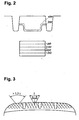
- the depth profile of the slats 14,15,16,17,18 is, as in Fig.2 is shown schematically on a profile block element shown by way of example with fins 100 and 200 formed.
- the fins are each formed with a substantially constant depth, which is reduced in the edge region of the profile block by 35 to 65%.
- the lamellae 100, which are closest to the profile block edge, are formed less deeply than the lamellae 200 in the interior of the profile block element.
- the edge area is between 3 and 6 mm thick
- the lamellae 14,15,16,17,18 are each formed with a sinusoidal course in the pad surface with the exception of the edge region of the respective tread block elements. Even along its depth extension, the course in sectional planes as described in patent application P 196 50 702.2 is parallel to the profile block element surface sinusoidal but with increasing depth with increasing phase shift.
- the phase shift in the depth direction takes place along a straight line which encloses an angle of> 0 ° with the radial. As in Fig. 3 is shown, takes place at two adjacent lamellae of a tread block element, the phase shift along two different lines with two opposite pitch directions.
- the helix angles of the two straight lines to the radial in one plane are alpha and beta.
- the lamellae of a tread block element are as described in the patent application P 196 50 702.2 alternately formed with a phase shift with the pitch angle alpha and with a phase shift to the pitch angle beta.
- the profile block elements are thereby crossed.
- Gamma is greater in the profile block elements 35 of the profile block row 5 than in the profile block elements 31, 32, 33, 34 of the profile block rows 1, 2, 3, 4.
- gamma is 40 ° in the tread block elements 35 and 20 ° in the tread block elements 31, 32, 33, 34.
- the width of the lamellae 14 to 18 is 0.3 to 0.6 mm, for example 0.4 mm.
- the width of the transverse grooves 9,10,12,13 is 3 to 8 mm.
- the width of the narrow transverse grooves 11 is 1 to 2 mm, for example, 1.1 mm.
- the tread block elements 33,34,35 additionally extending transversely to the slat direction ventilation lamellae 13 formed with a width of 0.8 to 1.3 mm, the adjacent lamellae with each other and the edge lamellae with the adjacent Connect grooves. Air pockets are thereby avoided.
- a rectilinear circumferential groove 22 having a width of 1 to 2 mm and a depth of 1.5 mm is additionally formed.
- the winter tire is a tubeless pneumatic vehicle tire of known radial type with steel or aramid reinforcements and, if necessary, with additional reinforcement known belt bandage of helically wound or juxtaposed bandage material with known suitable reinforcements - for example nylon.
Landscapes
- Engineering & Computer Science (AREA)
- Mechanical Engineering (AREA)
- Tires In General (AREA)
Claims (11)
- Profil de surface de roulement d'un pneu d'hiver pour des véhicules dont au moins deux roues de véhicule sont situées à l'extérieur de l'axe longitudinal du véhicule,- lequel profilé présente des rangées (1 à 5) de blocs profilés répartis dans la direction axiale entre un épaulement du pneu à l'autre épaulement du pneu, alignés dans le sens de la périphérie et séparés les uns des autres dans le sens axial par des rainures périphériques (6, 7, 8),- dans lequel une première rainure périphérique (7) divise le profilé de surface de roulement en deux zones (A; I) à fonctions différentes qui s'étendent toutes deux axialement entre l'épaulement associé du pneu et cette première rainure périphérique (7),- les éléments (31, 32) de bloc profilé de la partie axiale (A) qui s'étend entre cette rainure périphérique (7) et l'épaulement tourné vers le côté extérieur du véhicule lorsque le pneu est en position de fonctionnement sur le véhicule ont une rigidité en poussée transversale plus élevée que les éléments (33, 34, 35) de bloc profilé de la partie axiale (I) qui s'étend entre cette première rainure périphérique (7) et l'autre épaulement tourné vers le côté intérieur du véhicule lorsque le pneu est en position de fonctionnement sur le véhicule, tandis qu'au moins une autre rainure périphérique (8; 6) est formée et sépare l'une de l'autre deux rangées (5, 4; 2, 1) de blocs profilés aussi bien dans la partie axiale (1) qui s'étend entre cette première rainure périphérique et l'épaulement tourné vers le côté intérieur du véhicule lorsque le pneu est en position de fonctionnement que dans la partie axiale (A) qui s'étend entre cette première rainure périphérique (7) et l'épaulement tourné vers le côté extérieur du véhicule lorsque le pneu est en position de fonctionnement sur le véhicule, et qu'au moins dans la partie axiale (A), les rangées (1, 2) de blocs profilés sont formées par des éléments (31, 32) de bloc profilé disposés les uns derrière les autres dans le sens périphérique et séparés les uns des autres par des rainures transversales (9, 10) qui s'étendent obliquement de telle sorte que les bords transversaux des éléments (31, 32) de bloc profilé s'étendent obliquement et délimitent les éléments (31, 32) des blocs profilés dans la direction périphérique,caractérisé en ce que, dans la zone où elles débouchent dans la rainure périphérique (6), les rainures transversales (9; 10) sont décalées les unes par rapport aux autres dans la direction périphérique de telle sorte que dans leur prolongement qui correspond à l'obliquité de la rainure transversale (9; 10) correspondante, elles se terminent en venant buter contre une paroi latérale d'un élément (31; 32) de bloc profilé de l'autre rangée (1; 2) de blocs profilés.
- Profilé asymétrique de surface de roulement pour un pneu d'hiver selon les caractéristiques de la revendication 1, caractérisé en ce que les éléments (31, 32, 33, 34, 35) de bloc profilé des rangées (1, 2, 3, 4, 5) de blocs profilés sont tous dotés de lamelles (14, 15, 16, 17, 18) qui sont réalisés sous forme sinusoïdale dans la surface de l'élément du bloc profilé.
- Profilé asymétrique de surface de roulement pour un pneu d'hiver selon les caractéristiques d'une ou plusieurs des revendications précédentes, caractérisé en ce que les éléments (32, 33, 34) de bloc profilé des rangées (2, 3, 4) de blocs profilés sont tous configurés avec plusieurs lamelles (15, 16, 17) parallèles les unes autres qui s'étendent sur tout le bloc profilé correspondant et qui débouchent toutes des deux côtés dans une rainure périphérique (6, 7, 8) et/ou dans une rainure transversale (9 à 13).
- Profil asymétrique de surface de roulement d'un pneu d'hiver selon les caractéristiques d'une ou plusieurs des revendications précédentes, caractérisé en ce que- dans la partie axiale (I) qui s'étend entre la première rainure périphérique (7) et l'épaulement tourné vers le côté intérieur du véhicule lorsque le pneu est en position de fonctionnement sur le véhicule, les éléments (33, 34, 35) de bloc profilé des rangées (3, 4, 5) de blocs profilés sont configurés avec plusieurs lamelles (16 à 21) situées à distance les unes autres et qui s'étendent sur l'élément (33, 34, 35) de bloc profilé,- et en ce que la profondeur des lamelles d'un élément de bloc profilé qui traversent un élément de bloc profilé est plus petite sur le bord de l'élément de bloc profilé, et en particulier de 10 à 20 %, que leur profondeur entre les bords et à l'intérieur de l'élément de bloc profilé.
- Profilé asymétrique de surface de roulement d'un pneu d'hiver selon les caractéristiques d'une ou plusieurs des revendications précédentes,- dans lequel au moins une rangée de blocs profilés est formée d'éléments de bloc profilé disposés les uns derrière les autres dans la direction périphérique et séparés les uns des autres par des rainures transversales qui s'étendent obliquement de telle sorte que les bords transversaux des éléments de bloc profilé s'étendent obliquement et délimitent les éléments de bloc profilé dans la direction périphérique,- dans lequel les éléments de bloc profilé de cette rangée de blocs profilés sont configurés dans la direction axiale avec des bords longitudinaux qui délimitent latéralement les éléments de bloc profilé,- et dans lequel les éléments de bloc profilé de la rangée de blocs profilés sont configurés avec plusieurs lamelles séparées les unes des autres et qui s'étendent sur l'élément de bloc profilé, l'orientation des lamelles formant un angle compris entre 80 et 110° par rapport à la plus longue diagonale du trapèze formé par les bords transversaux et les bords longitudinaux.
- Profilé asymétrique de surface de roulement d'un pneu d'hiver selon les caractéristiques d'une ou plusieurs des revendications précédentes,- dans lequel les rangées de blocs profilés sont prévues dans les épaulements du pneu, au moins une autre rangée de blocs profilés étant réalisée entre les épaulements du pneu, les rangées de blocs profilés étant toutes formées d'éléments de bloc profilé disposés les uns derrière les autres dans la direction périphérique et séparés les uns des autres par des rainures transversales qui s'étendent obliquement de telle sorte que les bords transversaux des éléments de bloc profilé s'étendent obliquement et délimitent les éléments de bloc profilé dans la direction périphérique,- dans lequel les éléments de bloc profilé des rangées de blocs profilés sont configurés dans la direction axiale avec des bords longitudinaux qui délimitent les éléments de bloc profilé,- dans lequel les éléments de bloc profilé des rangées de blocs profilés sont configurés avec plusieurs lamelles séparées les unes autres et qui s'étendent sur l'élément de bloc profilé,- les lamelles des rangées de blocs profilés des épaulements ayant une orientation parallèle aux rainures transversales qui délimitent dans la direction périphérique les éléments de bloc profilé de la série de blocs profilés de l'épaulement concerné et- dans lequel les lamelles de la rangée de blocs profilés réalisées entre les rangées de blocs profilés des épaulements sont orientées sous un angle de 80 à 110° par rapport à la diagonale principale du trapèze formé par les bords transversaux et les bords longitudinaux.
- Profil asymétrique de surface de roulement d'un pneu d'hiver selon les caractéristiques d'une ou plusieurs des revendications précédentes, caractérisé en ce que des éléments (33, 34) de bloc profilé délimités par les rainures périphériques (7, 8) sont délimités l'un par rapport à l'autre par des rainures transversales (11, 12), les rainures transversales (11) s'étendant obliquement et présentant une largeur de 1 à 2 mm et les rainures transversales (12) s'étendant obliquement et présentant une largeur de 3 à 8 mm.
- Profil asymétrique de surface de roulement d'un pneu d'hiver selon les caractéristiques d'une ou plusieurs des revendications précédentes, caractérisé en ce que les éléments (33, 34) de bloc profilé des rangées (3, 4) de blocs profilés sont configurés de telle sorte qu'ils s'étendent axialement jusque dans la rangée (3; 4) de blocs profilés voisine de telle sorte qu'entre ces rangées (3, 4) de blocs profilés il n'y a pas de section transversale libre de rainure dans la direction périphérique.
- Profil asymétrique de surface de roulement d'un pneu d'hiver selon les caractéristiques de la revendication 1,- dans lequel tant le facteur de structure dans la direction périphérique que le facteur de structure dans la direction transversale et la direction périphérique sont de 10 à 50 % plus élevés dans les éléments de bloc profilé dans la direction axiale qui s'étend entre cette rainure périphérique et l'épaulement tourné vers le côté intérieur du véhicule lorsque le pneu est en position de fonctionnement sur le véhicule que dans les éléments de bloc profilé situés dans la partie axiale qui s'étend entre cette première rainure périphérique et l'épaulement tourné vers l'extérieur du véhicule lorsque le pneu est en position de fonctionnement sur le véhicule.
- Profil asymétrique de surface de roulement d'un pneu d'hiver selon les caractéristiques des revendications 1 ou 2,- dans lequel le pas dans la partie axiale qui s'étend entre la première rainure périphérique et l'épaulement qui est tourné vers l'intérieur du véhicule lorsque le pneu est en position de fonctionnement sur le véhicule est plus grand que dans la partie axiale qui s'étend entre cette première rainure périphérique et l'épaulement tourné vers l'extérieur du véhicule lorsque le pneu est en position de fonctionnement sur le véhicule.
- Profil asymétrique de surface de roulement d'un pneu d'hiver selon les caractéristiques d'une ou plusieurs des revendications précédentes,- dans lequel une autre rangée de blocs profilés qui est séparée par une rainure périphérique de la rangée de blocs profilés qui est formée dans l'épaulement tourné vers l'intérieur du véhicule lorsque le pneu est en position de fonctionnement sur le véhicule est formée dans la partie axiale qui s'étend entre cette première rainure périphérique et l'épaulement tourné vers le côté intérieur du véhicule lorsque le pneu est en position de fonctionnement sur le véhicule,- ces deux rangées voisines de blocs profilés étant toutes deux formées d'éléments de bloc profilé disposés les uns derrière les autres dans la direction périphérique et séparés les uns des autres par des rainures transversales qui s'étendent obliquement de telle sorte que les bords transversaux des éléments de bloc profilé s'étendent obliquement et délimitent les éléments de bloc profilé dans la direction périphérique, les rainures transversales s'étendant sous une pente constante dans les deux rangées de blocs profilés, axialement vers l'intérieur en partant des épaulements du pneu, les rainures transversales étant décalées les unes par rapport aux autres dans la direction périphérique à l'endroit où elles traversent la rainure périphérique de telle sorte que l'extrémité de la rainure transversale tournée vers la rainure périphérique prend dans la rangée de blocs d'épaulement la même position périphérique que l'extrémité de la rainure transversale tournée vers la rainure périphérique dans l'autre rangée de blocs profilés.
Priority Applications (1)
| Application Number | Priority Date | Filing Date | Title |
|---|---|---|---|
| DE29825135U DE29825135U1 (de) | 1997-12-04 | 1998-11-23 | Laufflächenprofil eines Winterreifens |
Applications Claiming Priority (3)
| Application Number | Priority Date | Filing Date | Title |
|---|---|---|---|
| DE19753819 | 1997-12-04 | ||
| DE19753819A DE19753819B4 (de) | 1997-12-04 | 1997-12-04 | Laufflächenprofil eines Winterreifens |
| EP98122227A EP0921020B1 (fr) | 1997-12-04 | 1998-11-23 | Profil de bande de roulement d'un pneu d'hiver |
Related Parent Applications (1)
| Application Number | Title | Priority Date | Filing Date |
|---|---|---|---|
| EP98122227A Division EP0921020B1 (fr) | 1997-12-04 | 1998-11-23 | Profil de bande de roulement d'un pneu d'hiver |
Publications (2)
| Publication Number | Publication Date |
|---|---|
| EP1529660A1 EP1529660A1 (fr) | 2005-05-11 |
| EP1529660B1 true EP1529660B1 (fr) | 2008-11-05 |
Family
ID=7850737
Family Applications (2)
| Application Number | Title | Priority Date | Filing Date |
|---|---|---|---|
| EP98122227A Expired - Lifetime EP0921020B1 (fr) | 1997-12-04 | 1998-11-23 | Profil de bande de roulement d'un pneu d'hiver |
| EP05001621A Expired - Lifetime EP1529660B1 (fr) | 1997-12-04 | 1998-11-23 | Profil de bande de roulement d'un pneu hivernal |
Family Applications Before (1)
| Application Number | Title | Priority Date | Filing Date |
|---|---|---|---|
| EP98122227A Expired - Lifetime EP0921020B1 (fr) | 1997-12-04 | 1998-11-23 | Profil de bande de roulement d'un pneu d'hiver |
Country Status (6)
| Country | Link |
|---|---|
| US (1) | US6619352B2 (fr) |
| EP (2) | EP0921020B1 (fr) |
| JP (1) | JPH11321240A (fr) |
| AT (2) | ATE413290T1 (fr) |
| CA (1) | CA2255254A1 (fr) |
| DE (3) | DE19753819B4 (fr) |
Families Citing this family (44)
| Publication number | Priority date | Publication date | Assignee | Title |
|---|---|---|---|---|
| DE10257487A1 (de) * | 2002-12-10 | 2004-07-01 | Continental Aktiengesellschaft | Fahrzeugluftreifen zum Einsatz unter winterlichen Fahrbedingungen |
| BR0215962A (pt) | 2002-12-19 | 2005-09-13 | Pirelli | Pneu para rodas de veìculo |
| DE10312488A1 (de) * | 2003-03-20 | 2004-09-30 | Continental Aktiengesellschaft | Fahrzeugreifen, insbesondere Winterreifen mit einem Laufstreifenprofil |
| DE10352145A1 (de) * | 2003-11-04 | 2005-06-09 | Continental Aktiengesellschaft | Fahrzeugluftreifen |
| DE10352149A1 (de) | 2003-11-04 | 2005-06-02 | Continental Aktiengesellschaft | Fahrzeugluftreifen |
| US7207364B2 (en) * | 2004-02-23 | 2007-04-24 | Continental Tire North America, Inc. | Radial tire with tread pattern having four or five circumferential ribs |
| US7213816B2 (en) * | 2004-06-23 | 2007-05-08 | Wal-Mart Stores, Inc. | Cart for stocking inventory and methods for making same |
| EP1619048B1 (fr) | 2004-07-15 | 2013-09-11 | Continental Reifen Deutschland GmbH | Bandage pneumatique pour vehicule |
| JP4568099B2 (ja) * | 2004-11-30 | 2010-10-27 | 株式会社ブリヂストン | 空気入りタイヤ |
| US20060118220A1 (en) * | 2004-12-06 | 2006-06-08 | The Goodyear Tire & Rubber Company | Pneumatic tire with elliptical shoulder |
| JP4656989B2 (ja) * | 2005-04-12 | 2011-03-23 | 株式会社ブリヂストン | 空気入りタイヤ |
| JP4215751B2 (ja) * | 2005-07-06 | 2009-01-28 | 横浜ゴム株式会社 | 空気入りタイヤ |
| JP4764085B2 (ja) * | 2005-07-22 | 2011-08-31 | 株式会社ブリヂストン | 空気入りタイヤ |
| JP5114890B2 (ja) * | 2006-07-28 | 2013-01-09 | 横浜ゴム株式会社 | 空気入りタイヤ |
| EP2058144B1 (fr) * | 2006-08-29 | 2010-12-01 | The Yokohama Rubber Co., Ltd. | Pneumatique |
| JP4899787B2 (ja) * | 2006-10-26 | 2012-03-21 | 横浜ゴム株式会社 | 空気入りタイヤ |
| JP4145337B2 (ja) * | 2007-01-17 | 2008-09-03 | 横浜ゴム株式会社 | 空気入りタイヤ |
| JP5161478B2 (ja) * | 2007-04-19 | 2013-03-13 | 住友ゴム工業株式会社 | 空気入りタイヤ |
| JP5092593B2 (ja) * | 2007-07-06 | 2012-12-05 | 横浜ゴム株式会社 | 空気入りタイヤ |
| JP4496254B2 (ja) * | 2008-01-15 | 2010-07-07 | 東洋ゴム工業株式会社 | 空気入りタイヤ |
| EP2311658B1 (fr) | 2008-07-10 | 2012-12-05 | Bridgestone Corporation | Pneumatique sans clous |
| JP5603563B2 (ja) * | 2009-04-24 | 2014-10-08 | 株式会社ブリヂストン | タイヤ |
| DE102009059169A1 (de) | 2009-12-16 | 2011-06-22 | Continental Reifen Deutschland GmbH, 30165 | Fahrzeugluftreifen |
| DE102010000210A1 (de) * | 2010-01-26 | 2011-07-28 | Continental Reifen Deutschland GmbH, 30165 | Fahrzeugluftreifen |
| US9481210B2 (en) | 2010-02-26 | 2016-11-01 | Bridgestone Corporation | Pneumatic tire |
| JP5461233B2 (ja) * | 2010-02-26 | 2014-04-02 | 株式会社ブリヂストン | 空気入りタイヤ |
| JP5419752B2 (ja) * | 2010-02-26 | 2014-02-19 | 株式会社ブリヂストン | 空気入りタイヤ |
| CA140299S (fr) * | 2010-11-29 | 2011-11-22 | Société de Technologie Michelin | Pneumatique |
| JP5480868B2 (ja) | 2011-10-07 | 2014-04-23 | 住友ゴム工業株式会社 | 空気入りタイヤ |
| JP5387659B2 (ja) * | 2011-11-14 | 2014-01-15 | 横浜ゴム株式会社 | 空気入りタイヤ |
| JP2013249018A (ja) * | 2012-06-01 | 2013-12-12 | Yokohama Rubber Co Ltd:The | 空気入りタイヤ |
| CN107972414B (zh) * | 2013-01-28 | 2020-03-10 | 倍耐力轮胎股份公司 | 轮胎 |
| FR3014750B1 (fr) * | 2013-12-17 | 2017-02-24 | Michelin & Cie | Bande de roulement comprenant des pavés et de fines rainures sur les pavés |
| EP3086957B1 (fr) * | 2013-12-23 | 2019-05-22 | Pirelli Tyre S.p.A. | Pneu pour des roues de véhicule comportant un motif de bande de roulement perfectionné |
| EP3192673B1 (fr) * | 2014-09-11 | 2019-04-03 | Bridgestone Corporation | Pneumatique |
| CN105216552B (zh) * | 2015-10-20 | 2017-05-10 | 特拓(青岛)轮胎技术有限公司 | 一种全天候四季轮胎胎面结构 |
| FR3044967B1 (fr) * | 2015-12-15 | 2017-12-22 | Michelin & Cie | Sommet de pneumatique pour vehicule lourd de type genie civil |
| JP6711172B2 (ja) * | 2016-06-27 | 2020-06-17 | 住友ゴム工業株式会社 | タイヤ |
| JP6769181B2 (ja) * | 2016-08-31 | 2020-10-14 | 住友ゴム工業株式会社 | タイヤ |
| JP2022097867A (ja) * | 2020-12-21 | 2022-07-01 | Toyo Tire株式会社 | 空気入りタイヤ |
| US20220355622A1 (en) * | 2021-05-05 | 2022-11-10 | The Goodyear Tire & Rubber Company | Tire tread |
| JP2022190895A (ja) * | 2021-06-15 | 2022-12-27 | 住友ゴム工業株式会社 | タイヤ及びタイヤと車両との組合せ体 |
| USD986811S1 (en) | 2021-08-16 | 2023-05-23 | Bridgestone Americas Tire Operations, Llc | Tire |
| USD986810S1 (en) | 2021-08-16 | 2023-05-23 | Bridgestone Americas Tire Operations, Llc | Tire |
Family Cites Families (27)
| Publication number | Priority date | Publication date | Assignee | Title |
|---|---|---|---|---|
| FR791250A (fr) * | 1935-06-13 | 1935-12-06 | Michelin & Cie | Perfectionnement à la surface de roulement des pneumatiques |
| DE1886124U (de) * | 1963-03-02 | 1964-01-16 | Willy Ellenrieder | Winter-allwetter-kraftfahrzeugreifen. |
| DE1505097A1 (de) * | 1963-07-19 | 1969-02-27 | Metzeler Ag | Kraftfahrzeugluftreifen mit ueber die ganze Breite der Laufflaeche unregelmaessigem Profil |
| FR2457185A1 (fr) * | 1979-05-23 | 1980-12-19 | Kleber Colombes | Pneumatique neige |
| DE3130574A1 (de) * | 1981-08-01 | 1983-02-17 | Bayer Ag, 5090 Leverkusen | Reifen mit asymmetrischem laufflaechenprofil |
| DE3130675A1 (de) * | 1981-08-03 | 1983-02-17 | Desowag-Bayer Holzschutz GmbH, 4000 Düsseldorf | Holzschutzmittelkonzentrat und daraus hergestelltes mittel zum konservieren von holz und holzwerkstoffen |
| DE3324649A1 (de) * | 1983-07-08 | 1985-01-31 | Continental Gummi-Werke Ag, 3000 Hannover | Fahrzeugluftreifen |
| US4546808A (en) * | 1984-01-06 | 1985-10-15 | The Goodyear Tire & Rubber Company | Pneumatic tire |
| US4702292A (en) * | 1986-03-18 | 1987-10-27 | The Goodyear Tire & Rubber Company | High performance all-season tire tread |
| US4815511A (en) * | 1986-03-18 | 1989-03-28 | The Goodyear Tire & Rubber Company | All-season high-performance radial-ply passenger pneumatic tire |
| JP2639449B2 (ja) * | 1986-11-07 | 1997-08-13 | 株式会社 ブリヂストン | 空気入りラジアルタイヤ |
| JP2514780Y2 (ja) * | 1987-02-20 | 1996-10-23 | 株式会社ブリヂストン | 空気入りタイヤ |
| JPS6452507A (en) * | 1987-05-08 | 1989-02-28 | Bridgestone Corp | Pneumatic tire pair |
| US4913208A (en) * | 1988-01-21 | 1990-04-03 | The Goodyear Tire & Rubber Company | Pneumatic radial-ply tire having block pattern tread |
| JPH0657485B2 (ja) * | 1989-03-27 | 1994-08-03 | 株式会社ブリヂストン | ラジアルタイヤ対 |
| AT401160B (de) * | 1991-05-21 | 1996-07-25 | Semperit Ag | Luftreifen mit einer lauffläche |
| US5360043A (en) * | 1991-07-26 | 1994-11-01 | The Goodyear Tire & Rubber Company | Asymmetric tread for a tire |
| JPH05178014A (ja) * | 1991-12-26 | 1993-07-20 | Yokohama Rubber Co Ltd:The | 空気入りタイヤ |
| AT400694B (de) * | 1992-04-03 | 1996-02-26 | Semperit Ag | Fahrzeugreifen |
| JPH06106916A (ja) * | 1992-09-30 | 1994-04-19 | Bridgestone Corp | 空気入りタイヤ |
| JPH06143941A (ja) * | 1992-11-05 | 1994-05-24 | Yokohama Rubber Co Ltd:The | 空気入りタイヤ |
| JPH07186622A (ja) * | 1993-12-27 | 1995-07-25 | Yokohama Rubber Co Ltd:The | 空気入りラジアルタイヤ |
| AT402178B (de) * | 1994-02-25 | 1997-02-25 | Semperit Ag | Laufstreifen für einen fahrzeugluftreifen |
| DE4427895A1 (de) * | 1994-08-08 | 1996-02-15 | Continental Ag | Fahrzeugreifen mit einer Lauffläche mit im wesentlichen axial verlaufenden Einschnitten |
| AT404341B (de) * | 1996-02-12 | 1998-10-27 | Semperit Ag | Fahrzeugluftreifen |
| DE19650702A1 (de) * | 1996-12-06 | 1998-06-10 | Continental Ag | Fahrzeugreifen mit einer Lauffläche mit im wesentlichen axial verlaufenden Einschnitten |
| JP3177466B2 (ja) * | 1997-02-06 | 2001-06-18 | 住友ゴム工業株式会社 | 空気入りタイヤ |
-
1997
- 1997-12-04 DE DE19753819A patent/DE19753819B4/de not_active Expired - Lifetime
-
1998
- 1998-11-23 EP EP98122227A patent/EP0921020B1/fr not_active Expired - Lifetime
- 1998-11-23 EP EP05001621A patent/EP1529660B1/fr not_active Expired - Lifetime
- 1998-11-23 DE DE59814317T patent/DE59814317D1/de not_active Expired - Lifetime
- 1998-11-23 AT AT05001621T patent/ATE413290T1/de active
- 1998-11-23 AT AT98122227T patent/ATE330799T1/de not_active IP Right Cessation
- 1998-11-23 DE DE59813613T patent/DE59813613D1/de not_active Expired - Lifetime
- 1998-12-03 US US09/204,291 patent/US6619352B2/en not_active Expired - Fee Related
- 1998-12-03 JP JP10344417A patent/JPH11321240A/ja not_active Withdrawn
- 1998-12-03 CA CA002255254A patent/CA2255254A1/fr not_active Abandoned
Also Published As
| Publication number | Publication date |
|---|---|
| EP0921020A2 (fr) | 1999-06-09 |
| DE59814317D1 (de) | 2008-12-18 |
| US20010035244A1 (en) | 2001-11-01 |
| CA2255254A1 (fr) | 1999-06-04 |
| JPH11321240A (ja) | 1999-11-24 |
| DE19753819A1 (de) | 1999-06-17 |
| EP0921020B1 (fr) | 2006-06-21 |
| EP1529660A1 (fr) | 2005-05-11 |
| EP0921020A3 (fr) | 2001-03-07 |
| DE59813613D1 (de) | 2006-08-03 |
| ATE330799T1 (de) | 2006-07-15 |
| ATE413290T1 (de) | 2008-11-15 |
| DE19753819B4 (de) | 2004-04-01 |
| US6619352B2 (en) | 2003-09-16 |
Similar Documents
| Publication | Publication Date | Title |
|---|---|---|
| EP1529660B1 (fr) | Profil de bande de roulement d'un pneu hivernal | |
| EP2349746B1 (fr) | Pneumatique de véhicule | |
| EP3110634B1 (fr) | Pneumatique de véhicule | |
| EP2222481A1 (fr) | Pneumatique de véhicule | |
| EP3300926B1 (fr) | Pneumatiques de véhicule | |
| EP1870258B1 (fr) | Pneu | |
| EP3750723B1 (fr) | Pneumatique de véhicule | |
| EP0588781B1 (fr) | Bandage pneumatique pour véhicule | |
| EP2138329B1 (fr) | Bande de roulement pour pneumatique | |
| EP3300925B1 (fr) | Pneumatiques de véhicule | |
| DE102007051645A1 (de) | Fahrzeugluftreifen | |
| EP2556971B1 (fr) | Pneus de véhicule | |
| EP3256335B1 (fr) | Pneumatique de véhicule | |
| EP3441241A1 (fr) | Pneumatique de véhicule | |
| EP3224060B1 (fr) | Pneumatique de véhicule | |
| WO2022253375A1 (fr) | Pneumatique de véhicule | |
| EP3663105B1 (fr) | Pneu de véhicule | |
| DE29825135U1 (de) | Laufflächenprofil eines Winterreifens | |
| WO2021013440A1 (fr) | Pneumatique de véhicule | |
| EP1506884B1 (fr) | Bande de roulement de pneu | |
| WO2011057852A1 (fr) | Sculpture de bande de roulement d'un pneumatique de véhicule | |
| EP2138328A1 (fr) | Pneus de véhicule | |
| EP3401125A1 (fr) | Profil de bande de roulement d'un pneu de véhicule | |
| EP3750722B1 (fr) | Pneumatique de véhicule | |
| WO2023208292A1 (fr) | Pneumatique de véhicule |
Legal Events
| Date | Code | Title | Description |
|---|---|---|---|
| PUAI | Public reference made under article 153(3) epc to a published international application that has entered the european phase |
Free format text: ORIGINAL CODE: 0009012 |
|
| AC | Divisional application: reference to earlier application |
Ref document number: 0921020 Country of ref document: EP Kind code of ref document: P |
|
| AK | Designated contracting states |
Kind code of ref document: A1 Designated state(s): AT CH DE FI FR GB IT LI SE |
|
| 17P | Request for examination filed |
Effective date: 20051111 |
|
| AKX | Designation fees paid |
Designated state(s): AT CH DE FI FR GB IT LI SE |
|
| GRAP | Despatch of communication of intention to grant a patent |
Free format text: ORIGINAL CODE: EPIDOSNIGR1 |
|
| RIC1 | Information provided on ipc code assigned before grant |
Ipc: B60C 11/12 20060101ALI20060725BHEP Ipc: B60C 11/03 20060101AFI20060725BHEP Ipc: B60C 11/11 20060101ALI20060725BHEP |
|
| GRAS | Grant fee paid |
Free format text: ORIGINAL CODE: EPIDOSNIGR3 |
|
| GRAA | (expected) grant |
Free format text: ORIGINAL CODE: 0009210 |
|
| AC | Divisional application: reference to earlier application |
Ref document number: 0921020 Country of ref document: EP Kind code of ref document: P |
|
| AK | Designated contracting states |
Kind code of ref document: B1 Designated state(s): AT CH DE FI FR GB IT LI SE |
|
| REG | Reference to a national code |
Ref country code: GB Ref legal event code: FG4D Free format text: NOT ENGLISH |
|
| REG | Reference to a national code |
Ref country code: CH Ref legal event code: EP |
|
| REF | Corresponds to: |
Ref document number: 59814317 Country of ref document: DE Date of ref document: 20081218 Kind code of ref document: P |
|
| REG | Reference to a national code |
Ref country code: SE Ref legal event code: TRGR |
|
| PG25 | Lapsed in a contracting state [announced via postgrant information from national office to epo] |
Ref country code: FI Free format text: LAPSE BECAUSE OF FAILURE TO SUBMIT A TRANSLATION OF THE DESCRIPTION OR TO PAY THE FEE WITHIN THE PRESCRIBED TIME-LIMIT Effective date: 20081105 |
|
| PLBE | No opposition filed within time limit |
Free format text: ORIGINAL CODE: 0009261 |
|
| STAA | Information on the status of an ep patent application or granted ep patent |
Free format text: STATUS: NO OPPOSITION FILED WITHIN TIME LIMIT |
|
| 26N | No opposition filed |
Effective date: 20090806 |
|
| GBPC | Gb: european patent ceased through non-payment of renewal fee |
Effective date: 20090205 |
|
| PG25 | Lapsed in a contracting state [announced via postgrant information from national office to epo] |
Ref country code: GB Free format text: LAPSE BECAUSE OF NON-PAYMENT OF DUE FEES Effective date: 20090205 |
|
| PGFP | Annual fee paid to national office [announced via postgrant information from national office to epo] |
Ref country code: SE Payment date: 20101112 Year of fee payment: 13 |
|
| REG | Reference to a national code |
Ref country code: CH Ref legal event code: PUE Owner name: CONTINENTAL REIFEN DEUTSCHLAND GMBH Free format text: CONTINENTAL AKTIENGESELLSCHAFT#VAHRENWALDER STRASSE 9#30165 HANNOVER (DE) -TRANSFER TO- CONTINENTAL REIFEN DEUTSCHLAND GMBH#VAHRENWALDERSTRASSE 9#30165 HANNOVER (DE) |
|
| REG | Reference to a national code |
Ref country code: FR Ref legal event code: ST Effective date: 20111202 |
|
| PG25 | Lapsed in a contracting state [announced via postgrant information from national office to epo] |
Ref country code: FR Free format text: LAPSE BECAUSE OF NON-PAYMENT OF DUE FEES Effective date: 20090105 |
|
| REG | Reference to a national code |
Ref country code: SE Ref legal event code: EUG |
|
| PG25 | Lapsed in a contracting state [announced via postgrant information from national office to epo] |
Ref country code: SE Free format text: LAPSE BECAUSE OF NON-PAYMENT OF DUE FEES Effective date: 20111124 |
|
| PGFP | Annual fee paid to national office [announced via postgrant information from national office to epo] |
Ref country code: AT Payment date: 20131113 Year of fee payment: 16 |
|
| REG | Reference to a national code |
Ref country code: AT Ref legal event code: MM01 Ref document number: 413290 Country of ref document: AT Kind code of ref document: T Effective date: 20141123 |
|
| PG25 | Lapsed in a contracting state [announced via postgrant information from national office to epo] |
Ref country code: AT Free format text: LAPSE BECAUSE OF NON-PAYMENT OF DUE FEES Effective date: 20141123 |
|
| PGFP | Annual fee paid to national office [announced via postgrant information from national office to epo] |
Ref country code: DE Payment date: 20171130 Year of fee payment: 20 |
|
| PGFP | Annual fee paid to national office [announced via postgrant information from national office to epo] |
Ref country code: IT Payment date: 20171124 Year of fee payment: 20 Ref country code: CH Payment date: 20171120 Year of fee payment: 20 |
|
| REG | Reference to a national code |
Ref country code: DE Ref legal event code: R071 Ref document number: 59814317 Country of ref document: DE |
|
| REG | Reference to a national code |
Ref country code: CH Ref legal event code: PL |