EP1523631B1 - Transmission a variation continue a poulies coniques - Google Patents
Transmission a variation continue a poulies coniques Download PDFInfo
- Publication number
- EP1523631B1 EP1523631B1 EP03764895A EP03764895A EP1523631B1 EP 1523631 B1 EP1523631 B1 EP 1523631B1 EP 03764895 A EP03764895 A EP 03764895A EP 03764895 A EP03764895 A EP 03764895A EP 1523631 B1 EP1523631 B1 EP 1523631B1
- Authority
- EP
- European Patent Office
- Prior art keywords
- belt
- shaft
- transmission according
- pulley transmission
- disk
- Prior art date
- Legal status (The legal status is an assumption and is not a legal conclusion. Google has not performed a legal analysis and makes no representation as to the accuracy of the status listed.)
- Expired - Lifetime
Links
- 230000005540 biological transmission Effects 0.000 claims description 30
- 239000012530 fluid Substances 0.000 claims description 3
- 230000002093 peripheral effect Effects 0.000 abstract description 2
- 125000006850 spacer group Chemical group 0.000 description 16
- 238000013461 design Methods 0.000 description 4
- 238000000034 method Methods 0.000 description 4
- 238000012986 modification Methods 0.000 description 3
- 230000004048 modification Effects 0.000 description 3
- 230000015572 biosynthetic process Effects 0.000 description 2
- 238000011161 development Methods 0.000 description 2
- 230000018109 developmental process Effects 0.000 description 2
- 238000006073 displacement reaction Methods 0.000 description 2
- 238000004519 manufacturing process Methods 0.000 description 2
- 239000000463 material Substances 0.000 description 2
- 230000004323 axial length Effects 0.000 description 1
- 210000001520 comb Anatomy 0.000 description 1
- 238000010276 construction Methods 0.000 description 1
- 230000003111 delayed effect Effects 0.000 description 1
- 230000001419 dependent effect Effects 0.000 description 1
- 238000009472 formulation Methods 0.000 description 1
- 239000000203 mixture Substances 0.000 description 1
- 238000012805 post-processing Methods 0.000 description 1
- 238000007789 sealing Methods 0.000 description 1
- 239000011265 semifinished product Substances 0.000 description 1
- 238000012360 testing method Methods 0.000 description 1
Images


Classifications
-
- F—MECHANICAL ENGINEERING; LIGHTING; HEATING; WEAPONS; BLASTING
- F16—ENGINEERING ELEMENTS AND UNITS; GENERAL MEASURES FOR PRODUCING AND MAINTAINING EFFECTIVE FUNCTIONING OF MACHINES OR INSTALLATIONS; THERMAL INSULATION IN GENERAL
- F16H—GEARING
- F16H15/00—Gearings for conveying rotary motion with variable gear ratio, or for reversing rotary motion, by friction between rotary members
- F16H15/02—Gearings for conveying rotary motion with variable gear ratio, or for reversing rotary motion, by friction between rotary members without members having orbital motion
- F16H15/04—Gearings providing a continuous range of gear ratios
-
- F—MECHANICAL ENGINEERING; LIGHTING; HEATING; WEAPONS; BLASTING
- F16—ENGINEERING ELEMENTS AND UNITS; GENERAL MEASURES FOR PRODUCING AND MAINTAINING EFFECTIVE FUNCTIONING OF MACHINES OR INSTALLATIONS; THERMAL INSULATION IN GENERAL
- F16H—GEARING
- F16H63/00—Control outputs from the control unit to change-speed- or reversing-gearings for conveying rotary motion or to other devices than the final output mechanism
- F16H63/02—Final output mechanisms therefor; Actuating means for the final output mechanisms
- F16H63/04—Final output mechanisms therefor; Actuating means for the final output mechanisms a single final output mechanism being moved by a single final actuating mechanism
- F16H63/06—Final output mechanisms therefor; Actuating means for the final output mechanisms a single final output mechanism being moved by a single final actuating mechanism the final output mechanism having an indefinite number of positions
- F16H63/065—Final output mechanisms therefor; Actuating means for the final output mechanisms a single final output mechanism being moved by a single final actuating mechanism the final output mechanism having an indefinite number of positions hydraulic actuating means
-
- F—MECHANICAL ENGINEERING; LIGHTING; HEATING; WEAPONS; BLASTING
- F16—ENGINEERING ELEMENTS AND UNITS; GENERAL MEASURES FOR PRODUCING AND MAINTAINING EFFECTIVE FUNCTIONING OF MACHINES OR INSTALLATIONS; THERMAL INSULATION IN GENERAL
- F16H—GEARING
- F16H55/00—Elements with teeth or friction surfaces for conveying motion; Worms, pulleys or sheaves for gearing mechanisms
- F16H55/32—Friction members
- F16H55/52—Pulleys or friction discs of adjustable construction
- F16H55/56—Pulleys or friction discs of adjustable construction of which the bearing parts are relatively axially adjustable
-
- F—MECHANICAL ENGINEERING; LIGHTING; HEATING; WEAPONS; BLASTING
- F16—ENGINEERING ELEMENTS AND UNITS; GENERAL MEASURES FOR PRODUCING AND MAINTAINING EFFECTIVE FUNCTIONING OF MACHINES OR INSTALLATIONS; THERMAL INSULATION IN GENERAL
- F16H—GEARING
- F16H61/00—Control functions within control units of change-speed- or reversing-gearings for conveying rotary motion ; Control of exclusively fluid gearing, friction gearing, gearings with endless flexible members or other particular types of gearing
Definitions
- the invention relates to a conical-pulley belt drive having a drive-side and an output-side conical pulley pair according to the preamble of claim 1.
- a conical pulley belt transmission is known from DE 100 25880A.
- Tapered belt transmissions are finding increasing use in passenger cars recently. They not only allow an increase in comfort, but also a reduction in consumption. In order to expand the range of use of conical-pulley belt transmissions, intensive development efforts have recently been made with regard to their torque transmission capability.
- FIG. 5 shows the upper half of a half-section through a per se known conical-pulley transmission.
- a shaft 2 of a cone pulley pair of a conical pulley belt transmission having an axis A-A is preferably formed integrally with a fixed pulley, not shown.
- a conical disk designated as a travel disk 6 is arranged on the shaft 2 in a torque-proof and axially displaceable manner.
- a support ring 8 is rigidly connected to the shaft 2, projecting from an axially directed, cylindrical annular wall 10 in the direction of the conical disk 6 in a radially central region.
- annular wall 14 is in sealed sliding contact with the annular wall 10 and the outer annular wall 16 is in sealed sliding contact with the outer periphery of the support ring 18.
- an inner pressure chamber 22 is formed between the shaft 2 and the conical disk and the annular walls 10 and 14 and between the ring walls 10, 14 and 16 and the bottom 24 of the wall portion 12 and the support ring 8, an outer pressure chamber 26 is formed.
- the axial length of the space 30 is such that over the entire adjustment path of the spacer disk 6 there is a pressure medium connection between the passage 28 and the passage 32.
- the space 30 directly adjoins a spline, not shown in detail, via which the rotationally fixed and axially displaceable connection between the travel plate 6 and the shaft 2 takes place.
- the outer pressure chamber 26 is connected via an opening formed in the support ring 8 channel 34, an annular channel 36 and a formed in the shaft 2 radial passage 38 with an axial passage of the shaft 2, of the axial passage, which is connected to the passage 28 , is separated.
- the two pressure chambers 22 and 26 can be acted upon in this way independently of each other with pressure medium, so that the displacement plate 6 can be moved in the direction of the fixed disk, not shown.
- a Fliehölsch 40 is formed, which serves in a conventional manner to compensate for speed influences on the forces acting in the combs 22 and 26 pressures.
- a problem with respect to the pressure medium supply of the inner pressure chamber 22 is that the trained as a transverse bore passage 32 of the spacer plate 5 and the space 30 is sealed according to FIG. 1 to the left to the fixed disk, not shown, only by a single sealing gap between the outer periphery the shaft 2 and the inner circumference of the conical disk 6 is formed. This means in practice relatively high leakage losses, especially when the pressure in the pressure chamber 22 is high.
- FIG. 6 shows an axial section through a pair of conical disks of a modified conical pulley belt transmission, wherein in FIG. 6 additionally the one formed integrally with the shaft 2 is shown Fixed disk 4 is shown.
- FIG. 6 only those areas which are essential with regard to the modification explained are identified by reference symbols.
- the radially inner pressure chamber 22 is not supplied via a radial passage 32 formed in the shoulder disk 6 in the shoulder region of a neck 44 of the travel disk 6, but the end region of the neck 44 facing the support ring 8 the fixed disk 6 is provided with a generally radially extending groove 46, wherein the geometric assignment is such that in Fig. 1 fully shifted to the right rear plate 6, the groove 46, a total radially extending passage 46 of the shaft 2 overlaps, so that constantly a pressure medium connection between an axial passage 50 of the shaft and the pressure chamber 22 consists.
- the section C of Fig. 6 shows an embodiment in which the groove 46 is formed in the end face of the neck 44 as a simple straight groove, which can already be forged or milled in the semifinished product of the conical disk 6.
- a modified embodiment of the groove 46 is shown, in which the groove is formed as a Ecknut whose depth is only radially inward directly on the diameter of the travel disc or the neck of the spacer plate is large to ensure the Strörnungsstoff trimgang and, to the outside formed with reduced depth. This reduces the stress on the material.
- the invention has the object of providing a conical-pulley with a drive-side and a driven-side cone pulley pair according to the preamble of claim 1 such that the immediately adjacent to the shaft pressure chamber works well even at very high, transmitted from the fixed torque, working properly, and the oil supply to ensure from the shaft in the pressure cylinder of the conical disk pairs while reducing the component stress, especially at very low temperatures.
- This object is in a conical-pulley with a drive-side and a driven-side cone pulley pair, in each of which a cone pulley pair is arranged on a shaft, a one-piece or multi-part formed with the shaft fixed disk, and a spacer disc with the shaft rotatably and axially slidably connected, also has a support ring axially fixed to the shaft at a distance from a rear side of the travel disc, at least one axially formed between the support ring and the back of the travel disc pressure chamber which has a opening in a peripheral surface of the shaft, formed in the shaft passage with hydraulic fluid is supplied, the pressure of which is displaceable for displacement of the spacer is achieved in that an end portion of an outwardly guided on the shaft inner surface of the spacer at its maximum distance from the fixed disk passes over the mouth of the passage and the hyd Raulikschijn between the passage and the pressure chamber substantially via leakage gaps between the inner surface of the path plate and the outer surface of the shaft takes place.
- the end region deforms oval as a result of a tilting moment acting from the conical disk.
- This oval deformation favors the formation of leakage gaps, via which the pressure medium supply takes place.
- the support ring facing side of the mouth of the passage or the entire mouth is countersunk.
- the outer surface of the shaft and the support ring facing the end of the travel disc is provided with a chamfer.
- the inclination of the chamfer is advantageously between 2 ° and 10 °.
- the inclination of the chamfer takes advantage outwardly, d. H. towards the support ring, too.
- the length is advantageously between 0.5 and 5 mm.
- the chamfer is designed as a rounding, which merges tangentially or with a bend in a cylindrical inner surface of the spacer plate.
- a further advantageous embodiment of the invention provides that the shaft preferably in the immediate vicinity of its taper to the seat of the support ring towards at least one radial with a countersink in the form of a chamfer or rounding providing through-hole and that at the same time the support ring at the point where the conical disk this strikes, is provided with a circumferential groove .
- this groove can also be attached to a remote.
- a circumferential recess preferably in the form of a chamfer or curvature, is present at the neck end of the conical disk.
- the mountability is thus significantly easier, since the assignment of shaft bore and oil groove of the conical disk deleted.
- This circumferential recess in the seal carrier can already be provided in the production of blank, resulting in a significant cost savings.
- the total radial passage 28 of the shaft 2 which connects an axial passage 52 of the shaft 2 with the radially inner pressure chamber 22, is arranged such that the mouth 52 of the total radial passage 28 from the end region of the Neck 44 of the spacer plate 6 is run over when the spacer plate 6 is moved as shown in FIG. 1 to the right.
- satisfactory experimental results have been achieved, but the pressure build-up in the pressure chamber 22 is delayed from the pressure build-up in the axial passage 46, for example of the order of a few hundred milliseconds.
- the detail E shows an advantageous detail of the embodiment according to FIG. 1, with which the gap cross-sections existing between the pressure chamber 22 and the passage 28 are enlarged in order to reduce the delay of the pressure build-up.
- the passage 28, which is normally formed as a simple radial or obliquely directed to the radial direction bore of the shaft 2, has on its the windshield 6 side facing a countersink 60 which the gap passage cross-section for the hydraulic fluid, as seen immediately from the section E, increased.
- the inclination of such a chamfer 62 relative to the axial direction is for example of the order of about 2 °.
- the countersink 60 terminates axially on the right approximately in a region which corresponds to the radial end face of the neck 44 in its fully shifted to the right position.
- the angle ⁇ , the chamfer 60 forms with the axis of the passage 28 is advantageously about 45 °.
- the chamfer 60 terminates at a distance a from a step of the shaft 2 against which the support ring 8 (FIG. 1) abuts, wherein the support ring 8 forms a stop for the fixed disk 6.
- the dimension a is, for example, about 0.4 mm.
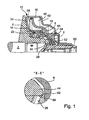
- the detail F of FIG. 2 shows a plan view of the mouth 52 of the passage 28 in the direction of the arrow F '.
- Fig. 3 shows a detail of the formation of the end portion of the neck 44:
- a chamfer 64 is formed, which in a first region 66 has a pitch (angle X) of about 2 ° and then inclined by a larger angle Z to the axis AA (FIG. 1) up to 10 °.
- the dimension A, d. H. the distance between the beginning of the chamfer 64 and the end of the neck 44 is about 2.5 mm.
- the dimension B, d. H. the distance of the beginning of the second region from the end of the neck 44 is about 1.5 mm.
- Fig. 4 shows a comparison with FIG. 3 modified embodiment in which the chamfer 64 is rounded, for example in the form of a circular arc with radius R, which starts at a distance A of about 3 mm from the axial end of the neck 44 and tangentially or with a kink to the axially parallel cylindrical inner surface of the neck 44 attaches.
- Fig. 7 shows a further constructive embodiment of a conical disk pair and the support ring 8 and the cylindrical annular wall 16.
- the conical disks are each divided. So they each consist of the disc 6 itself and a disc carrier 6a, which are preferably bolted together.
- This constructive design has the advantage that when wear indicator of the discs 6 they can be solved in a simple way from the disc carrier 6a and replaced by new discs 6
- Fig. 8 shows the view X with a solution, the mouth 52 of the passage 28.
- This mouth 52 is in this case, as shown in Fig. 1, provided with a nose 60. Since the Wegniknxx 6 a is provided in the contact region to the passage 28 with a chamfer 70, the pressure medium from the passage 28 via the small gap, which is formed by the two chamfers 60 and 62 and the axial groove 70, flow into the pressure chamber 22.
- FIG. 9 Another possibility of forwarding the pressure medium is apparent from the structural design according to view X of FIG. 9.
- the support ring 8 is deposited over the passage 28. This ensures that the pressure medium from the passage 28 can pass directly through the axial groove 70 into the pressure chamber 22.
- To increase the inlet cross-section or to improve the flow behavior of the pressure medium of the disk carrier 6a is provided in the contact region to the shaft 2 with a chamfer 62.
- the invention is not limited to conical disk pairs with an arrangement of pressure chambers according to FIG. 1 or FIG. 7. It is particularly suitable for all types of pressure chambers, in which a directly adjacent to the shaft pressure chamber is supplied at the back of the travel disc through the shaft with pressure medium, for example, arrangements with only one pressure chamber, or even arrangements with per se known pressure chamber arrangement in tandem design ,
Landscapes
- Engineering & Computer Science (AREA)
- General Engineering & Computer Science (AREA)
- Mechanical Engineering (AREA)
- Transmissions By Endless Flexible Members (AREA)
- Pulleys (AREA)
- Hydraulic Motors (AREA)
- Holding Or Fastening Of Disk On Rotational Shaft (AREA)
- General Details Of Gearings (AREA)
Claims (21)
- Variateur à enroulement à disques coniques avec une paire de disques coniques menants (4, 6) et une paire de disques coniques menés (10, 12), dont les paires de disques coniques- sont disposées sur un arbre (2, 8) et avec- un disque fixe (4) constitué en une ou plusieurs parties avec l'arbre- un disque mobile (6) bloqué en rotation sur l'arbre et mobile en direction axiale- une bague d'appui (8) fixée sur l'arbre (2) et immobile en direction axiale, écartée d'une face arrière du disque mobile (6)- au moins une chambre de compression (22) constituée, en direction axiale, entre la bague d'appui (8) et la face arrière du disque mobile (6), alimentée par un fluide de pression hydraulique via un ou plusieurs passages (28) situés dans l'arbre (2) et débouchant sur une surface périphérique de l'arbre (2) et dont la pression nécessaire pour déplacer le disque mobile (6) peut être modifiée et- une extrémité (44) d'une surface intérieure du disque mobile (6) guidée sur l'arbre (2) qui dépasse l'orifice (54) du passage (28) lors de son éloignement maximal du disque fixe (4), caractérisé par le fait que la liaison de fluide hydraulique entre le passage (28) et la chambre de compression (22) se fait essentiellement via des interstices de fuite entre la surface intérieure du disque mobile (6) et la surface extérieure de l'arbre (2).
- Variateur à enroulement à disques coniques selon la revendication 1, caractérisé par le fait que le disque mobile comporte, en direction de la bague d'appui, un col se terminant dans la zone d'extrémité.
- Variateur à enroulement à disques coniques selon la revendication 1 ou 2, caractérisé par le fait que la zone d'extrémité se décale en direction radiale en raison d'un couple de renversement agissant à partir du disque conique et faisant ainsi apparaître sur une partie de la périphérie un jeu radial entre la surface intérieure et l'arbre.
- Variateur à enroulement à disques coniques selon la revendication 1 ou 2, caractérisé par le fait que la zone d'extrémité se déforme de façon ovale en raison d'un couple de renversement agissant à partir du disque conique.
- Variateur à enroulement à disques coniques selon la revendication 1 ou 2, caractérisé par le fait que la zone d'extrémité se dégage en direction axiale de la bague d'appui sur une partie de la périphérie en raison d'un couple de renversement agissant à partir du disque conique.
- Variateur à enroulement à disques coniques selon l'une quelconque des revendications 1 à 3, caractérisé par le fait que le côté de l'orifice orienté vers la bague d'appui ou l'orifice entier du passage est fraisé.
- Variateur à enroulement à disques coniques selon l'une quelconque des revendications 1 à 4, caractérisé par le fait que l'extrémité du disque mobile orientée vers la surface extérieure de l'arbre et la bague d'appui comporte un chanfrein.
- Variateur à enroulement à disques coniques selon la revendication 5, caractérisé par le fait que l'inclinaison du chanfrein varie entre 2° et 10°.
- Variateur à enroulement à disques coniques selon la revendication 5, caractérisé par le fait que la longueur du chanfrein varie entre 0,5 et 5 mm.
- Variateur à enroulement à disques coniques selon la revendication 5 ou 6, caractérisé par le fait que l'inclinaison du chanfrein croît axialement vers l'extérieur.
- Variateur à enroulement à disques coniques selon la revendication 5 ou 6, caractérisé par le fait que la longueur de la partie plus inclinée du chanfrein s'étend sur 20 à 80 % de la longueur totale du chanfrein.
- Variateur à enroulement à disques coniques selon la revendication 5, caractérisé par le fait que le chanfrein est réalisé sous forme d'arrondi, lequel est raccordé de façon tangentielle ou avec un coude à une surface intérieure cylindrique du disque mobile.
- Variateur à enroulement à disques coniques selon la revendication 5, caractérisé par le fait que le rayon de l'arrondi varie entre 5 et 50 mm.
- Variateur à enroulement à disques coniques selon la revendication 5, caractérisé par le fait que l'étendue axiale de l'arrondi varie entre 1 et 8 mm.
- Variateur à enroulement à disques coniques selon la revendication 1, caractérisé par le fait que l'arbre présente, de préférence à proximité de son rétrécissement vers le siège de la bague d'appui, au moins un trou de passage radial.
- Variateur à enroulement à disques coniques selon la revendication 9, caractérisé par le fait que le trou de passage comporte une fraisure à ses deux extrémités.
- Variateur à enroulement à disques conique selon les revendications 9 et 10, caractérisé par le fait que la fraisure se présente sous la forme d'un chanfrein.
- Variateur à enroulement à disques conique selon les revendications 9 à 11, caractérisé par le fait que la fraisure se présente sous la forme d'un arrondi.
- Variateur à enroulement à disques conique selon les revendications 1 et 9, caractérisé par le fait que la bague d'appui comporte un épaulement et est pourvue d'une gorge circulaire à l'endroit où le porte-disque mobile prend appui.
- Variateur à enroulement à disques conique selon l'une quelconque des revendications 9 à 13, caractérisé par le fait qu'un évidement circulaire est prévu à l'extrémité du col du disque conique.
- Variateur à enroulement à disques conique selon la revendication 14, caractérisé par le fait que l'évidement circulaire se présente sous la forme d'un chanfrein ou d'un congé concave.
Applications Claiming Priority (3)
| Application Number | Priority Date | Filing Date | Title |
|---|---|---|---|
| DE10231790 | 2002-07-15 | ||
| DE10231790 | 2002-07-15 | ||
| PCT/DE2003/002373 WO2004010029A2 (fr) | 2002-07-15 | 2003-07-15 | Transmission a variation continue a poulies coniques |
Publications (2)
| Publication Number | Publication Date |
|---|---|
| EP1523631A2 EP1523631A2 (fr) | 2005-04-20 |
| EP1523631B1 true EP1523631B1 (fr) | 2006-08-09 |
Family
ID=30009957
Family Applications (1)
| Application Number | Title | Priority Date | Filing Date |
|---|---|---|---|
| EP03764895A Expired - Lifetime EP1523631B1 (fr) | 2002-07-15 | 2003-07-15 | Transmission a variation continue a poulies coniques |
Country Status (8)
| Country | Link |
|---|---|
| EP (1) | EP1523631B1 (fr) |
| JP (1) | JP4582634B2 (fr) |
| KR (1) | KR20050025343A (fr) |
| CN (1) | CN100366955C (fr) |
| AT (1) | ATE335942T1 (fr) |
| AU (1) | AU2003250786A1 (fr) |
| DE (4) | DE10392780D2 (fr) |
| WO (1) | WO2004010029A2 (fr) |
Families Citing this family (3)
| Publication number | Priority date | Publication date | Assignee | Title |
|---|---|---|---|---|
| DE502005005177D1 (de) * | 2004-10-23 | 2008-10-09 | Luk Lamellen & Kupplungsbau | Kegelscheibenumschlingungsgetriebe, sowie Fahrzeug mit einem derartigem Getriebe |
| WO2018151000A1 (fr) * | 2017-02-20 | 2018-08-23 | ユニプレス株式会社 | Élément de paroi de séparation pour poulie primaire dans une transmission à variation continue de type à courroie |
| JP6655669B2 (ja) * | 2018-07-09 | 2020-02-26 | 本田技研工業株式会社 | 動力伝達装置の制御装置 |
Family Cites Families (9)
| Publication number | Priority date | Publication date | Assignee | Title |
|---|---|---|---|---|
| JPS62177349A (ja) * | 1986-01-29 | 1987-08-04 | Toyota Motor Corp | ベルト式無段変速機 |
| JP2516843Y2 (ja) * | 1990-02-08 | 1996-11-13 | 三ツ星ベルト株式会社 | 金属ベルト用変速プーリ |
| JP2917054B2 (ja) * | 1990-09-28 | 1999-07-12 | 富士重工業株式会社 | ベルト式無段変速機のプーリシリンダ装置 |
| JP3134637B2 (ja) * | 1993-11-09 | 2001-02-13 | 日産自動車株式会社 | 無段変速機の油圧室構造 |
| JP3156511B2 (ja) * | 1994-08-02 | 2001-04-16 | 日産自動車株式会社 | 無段変速機の潤滑用油路 |
| JP3277087B2 (ja) * | 1995-01-10 | 2002-04-22 | 愛知機械工業株式会社 | 可動フランジを備えた無段変速機 |
| DE19857710B4 (de) * | 1997-12-22 | 2013-02-21 | Schaeffler Technologies AG & Co. KG | Getriebe |
| JP2001004000A (ja) * | 1999-05-27 | 2001-01-09 | Luk Lamellen & Kupplungsbau Gmbh | 円錐形ディスク式巻掛け伝動装置のための円錐形ディスク対 |
| JP4848559B2 (ja) * | 2000-12-20 | 2011-12-28 | シェフラー テクノロジーズ ゲゼルシャフト ミット ベシュレンクテル ハフツング ウント コンパニー コマンディートゲゼルシャフト | 組み込まれたトルク感応器を備えた無段変速可能な円錐形プーリ巻掛け伝動装置 |
-
2003
- 2003-07-15 AU AU2003250786A patent/AU2003250786A1/en not_active Abandoned
- 2003-07-15 CN CNB038169029A patent/CN100366955C/zh not_active Expired - Fee Related
- 2003-07-15 EP EP03764895A patent/EP1523631B1/fr not_active Expired - Lifetime
- 2003-07-15 DE DE10392780T patent/DE10392780D2/de not_active Expired - Fee Related
- 2003-07-15 DE DE20380250U patent/DE20380250U1/de not_active Expired - Lifetime
- 2003-07-15 JP JP2004522126A patent/JP4582634B2/ja not_active Expired - Fee Related
- 2003-07-15 DE DE10331910A patent/DE10331910A1/de not_active Withdrawn
- 2003-07-15 KR KR1020057000494A patent/KR20050025343A/ko not_active Ceased
- 2003-07-15 DE DE50304594T patent/DE50304594D1/de not_active Expired - Lifetime
- 2003-07-15 WO PCT/DE2003/002373 patent/WO2004010029A2/fr not_active Ceased
- 2003-07-15 AT AT03764895T patent/ATE335942T1/de not_active IP Right Cessation
Also Published As
| Publication number | Publication date |
|---|---|
| ATE335942T1 (de) | 2006-09-15 |
| CN1668865A (zh) | 2005-09-14 |
| JP2005533227A (ja) | 2005-11-04 |
| KR20050025343A (ko) | 2005-03-14 |
| AU2003250786A1 (en) | 2004-02-09 |
| DE10392780D2 (de) | 2005-03-03 |
| DE50304594D1 (de) | 2006-09-21 |
| JP4582634B2 (ja) | 2010-11-17 |
| CN100366955C (zh) | 2008-02-06 |
| EP1523631A2 (fr) | 2005-04-20 |
| DE10331910A1 (de) | 2004-02-05 |
| DE20380250U1 (de) | 2005-02-17 |
| WO2004010029A3 (fr) | 2004-04-08 |
| WO2004010029A2 (fr) | 2004-01-29 |
Similar Documents
| Publication | Publication Date | Title |
|---|---|---|
| EP3197701B1 (fr) | Ensemble embrayage et ensemble de transmission comprenant un ensemble embrayage | |
| EP2470808B1 (fr) | Système de double embrayage pour une boîte de vitesses munie de deux arbres d'entrée | |
| EP1857701B1 (fr) | Disposition d'embrayage multiple | |
| DE4327519C2 (de) | Vorrichtung zur Steuerung einer Kupplung | |
| EP3027455B1 (fr) | Chaîne cinématique d'un véhicule automobile | |
| DE19802605B4 (de) | Aufbau eines Riemenscheibenzylinders in einem stetig veränderbaren Getriebe der Riementype | |
| EP2438323B1 (fr) | Ensemble comprenant au moins un embrayage à crabots | |
| DE10160865A1 (de) | Stufenlos verstellbares Kegelscheibenumschlingungsgetriebe mit integriertem Drehmomentfühler | |
| DE2549408A1 (de) | Achsantrieb mit einem differentialgetriebe | |
| DE102006001334B3 (de) | Getriebeanordnung zur variablen Drehmomentverteilung | |
| DE10025880A1 (de) | Kegelscheibenpaar für ein Kegelscheibenumschlingungsgetriebe | |
| EP2002147A1 (fr) | Dispositif de detection du couple de rotation sur une transmission a courroie sur poulies coniques | |
| DE1804621A1 (de) | Kraftuebertragungseinrichtung | |
| EP1523631B1 (fr) | Transmission a variation continue a poulies coniques | |
| EP2063146A1 (fr) | Dispositif d'embrayage à disques multiples | |
| DE19801279B4 (de) | Kontinuierlich variables Getriebe | |
| DE102006062200B4 (de) | Differentialanordnung mit mehrteiligem Differentialkorb und Verfahren zur Herstellung einer Differentialanordnung | |
| WO2004025142A1 (fr) | Transmission a variation continue pourvue de poulies coniques | |
| EP1285184B1 (fr) | Boite de vitesses automatique | |
| DE10203944A1 (de) | Stufenlos verstellbares Kegelscheibenumschlingungsgetriebe mit integriertem Drehmomentfühler | |
| DE102021113629A1 (de) | Nasse doppelkupplung | |
| DE4318475B4 (de) | Scheibensatz für ein stufenloses Umschlingungsgetriebe | |
| DE112006002813B4 (de) | Kegelscheibenumschlingungsgetriebe sowie Fahrzeug mit einem derartigen Getriebe | |
| DE10361332B4 (de) | Variatorscheibe und Variator für ein Toroidgetriebe | |
| DE60101306T2 (de) | Reibscheibe für eine Nasskupplung |
Legal Events
| Date | Code | Title | Description |
|---|---|---|---|
| PUAI | Public reference made under article 153(3) epc to a published international application that has entered the european phase |
Free format text: ORIGINAL CODE: 0009012 |
|
| 17P | Request for examination filed |
Effective date: 20050215 |
|
| AK | Designated contracting states |
Kind code of ref document: A2 Designated state(s): AT BE BG CH CY CZ DE DK EE ES FI FR GB GR HU IE IT LI LU MC NL PT RO SE SI SK TR |
|
| AX | Request for extension of the european patent |
Extension state: AL LT LV MK |
|
| DAX | Request for extension of the european patent (deleted) | ||
| GRAP | Despatch of communication of intention to grant a patent |
Free format text: ORIGINAL CODE: EPIDOSNIGR1 |
|
| GRAS | Grant fee paid |
Free format text: ORIGINAL CODE: EPIDOSNIGR3 |
|
| GRAA | (expected) grant |
Free format text: ORIGINAL CODE: 0009210 |
|
| AK | Designated contracting states |
Kind code of ref document: B1 Designated state(s): AT BE BG CH CY CZ DE DK EE ES FI FR GB GR HU IE IT LI LU MC NL PT RO SE SI SK TR |
|
| PG25 | Lapsed in a contracting state [announced via postgrant information from national office to epo] |
Ref country code: IT Free format text: LAPSE BECAUSE OF FAILURE TO SUBMIT A TRANSLATION OF THE DESCRIPTION OR TO PAY THE FEE WITHIN THE PRESCRIBED TIME-LIMIT;WARNING: LAPSES OF ITALIAN PATENTS WITH EFFECTIVE DATE BEFORE 2007 MAY HAVE OCCURRED AT ANY TIME BEFORE 2007. THE CORRECT EFFECTIVE DATE MAY BE DIFFERENT FROM THE ONE RECORDED. Effective date: 20060809 Ref country code: FI Free format text: LAPSE BECAUSE OF FAILURE TO SUBMIT A TRANSLATION OF THE DESCRIPTION OR TO PAY THE FEE WITHIN THE PRESCRIBED TIME-LIMIT Effective date: 20060809 Ref country code: CZ Free format text: LAPSE BECAUSE OF FAILURE TO SUBMIT A TRANSLATION OF THE DESCRIPTION OR TO PAY THE FEE WITHIN THE PRESCRIBED TIME-LIMIT Effective date: 20060809 Ref country code: SI Free format text: LAPSE BECAUSE OF FAILURE TO SUBMIT A TRANSLATION OF THE DESCRIPTION OR TO PAY THE FEE WITHIN THE PRESCRIBED TIME-LIMIT Effective date: 20060809 Ref country code: RO Free format text: LAPSE BECAUSE OF FAILURE TO SUBMIT A TRANSLATION OF THE DESCRIPTION OR TO PAY THE FEE WITHIN THE PRESCRIBED TIME-LIMIT Effective date: 20060809 Ref country code: IE Free format text: LAPSE BECAUSE OF FAILURE TO SUBMIT A TRANSLATION OF THE DESCRIPTION OR TO PAY THE FEE WITHIN THE PRESCRIBED TIME-LIMIT Effective date: 20060809 Ref country code: SK Free format text: LAPSE BECAUSE OF FAILURE TO SUBMIT A TRANSLATION OF THE DESCRIPTION OR TO PAY THE FEE WITHIN THE PRESCRIBED TIME-LIMIT Effective date: 20060809 |
|
| REG | Reference to a national code |
Ref country code: GB Ref legal event code: FG4D Free format text: NOT ENGLISH |
|
| REG | Reference to a national code |
Ref country code: CH Ref legal event code: EP |
|
| REG | Reference to a national code |
Ref country code: IE Ref legal event code: FG4D Free format text: LANGUAGE OF EP DOCUMENT: GERMAN |
|
| REF | Corresponds to: |
Ref document number: 50304594 Country of ref document: DE Date of ref document: 20060921 Kind code of ref document: P |
|
| PG25 | Lapsed in a contracting state [announced via postgrant information from national office to epo] |
Ref country code: BG Free format text: LAPSE BECAUSE OF FAILURE TO SUBMIT A TRANSLATION OF THE DESCRIPTION OR TO PAY THE FEE WITHIN THE PRESCRIBED TIME-LIMIT Effective date: 20061109 Ref country code: DK Free format text: LAPSE BECAUSE OF FAILURE TO SUBMIT A TRANSLATION OF THE DESCRIPTION OR TO PAY THE FEE WITHIN THE PRESCRIBED TIME-LIMIT Effective date: 20061109 Ref country code: SE Free format text: LAPSE BECAUSE OF FAILURE TO SUBMIT A TRANSLATION OF THE DESCRIPTION OR TO PAY THE FEE WITHIN THE PRESCRIBED TIME-LIMIT Effective date: 20061109 |
|
| PG25 | Lapsed in a contracting state [announced via postgrant information from national office to epo] |
Ref country code: ES Free format text: LAPSE BECAUSE OF FAILURE TO SUBMIT A TRANSLATION OF THE DESCRIPTION OR TO PAY THE FEE WITHIN THE PRESCRIBED TIME-LIMIT Effective date: 20061120 |
|
| GBT | Gb: translation of ep patent filed (gb section 77(6)(a)/1977) |
Effective date: 20061106 |
|
| PG25 | Lapsed in a contracting state [announced via postgrant information from national office to epo] |
Ref country code: PT Free format text: LAPSE BECAUSE OF FAILURE TO SUBMIT A TRANSLATION OF THE DESCRIPTION OR TO PAY THE FEE WITHIN THE PRESCRIBED TIME-LIMIT Effective date: 20070109 |
|
| REG | Reference to a national code |
Ref country code: IE Ref legal event code: FD4D |
|
| EN | Fr: translation not filed | ||
| PLBE | No opposition filed within time limit |
Free format text: ORIGINAL CODE: 0009261 |
|
| STAA | Information on the status of an ep patent application or granted ep patent |
Free format text: STATUS: NO OPPOSITION FILED WITHIN TIME LIMIT |
|
| 26N | No opposition filed |
Effective date: 20070510 |
|
| BERE | Be: lapsed |
Owner name: LUK LAMELLEN UND KUPPLUNGSBAU BETEILIGUNGS K.G. Effective date: 20070731 |
|
| REG | Reference to a national code |
Ref country code: CH Ref legal event code: PL |
|
| PG25 | Lapsed in a contracting state [announced via postgrant information from national office to epo] |
Ref country code: GR Free format text: LAPSE BECAUSE OF FAILURE TO SUBMIT A TRANSLATION OF THE DESCRIPTION OR TO PAY THE FEE WITHIN THE PRESCRIBED TIME-LIMIT Effective date: 20061110 Ref country code: CH Free format text: LAPSE BECAUSE OF NON-PAYMENT OF DUE FEES Effective date: 20070731 Ref country code: FR Free format text: LAPSE BECAUSE OF FAILURE TO SUBMIT A TRANSLATION OF THE DESCRIPTION OR TO PAY THE FEE WITHIN THE PRESCRIBED TIME-LIMIT Effective date: 20070511 Ref country code: LI Free format text: LAPSE BECAUSE OF NON-PAYMENT OF DUE FEES Effective date: 20070731 Ref country code: MC Free format text: LAPSE BECAUSE OF NON-PAYMENT OF DUE FEES Effective date: 20070731 |
|
| PG25 | Lapsed in a contracting state [announced via postgrant information from national office to epo] |
Ref country code: EE Free format text: LAPSE BECAUSE OF FAILURE TO SUBMIT A TRANSLATION OF THE DESCRIPTION OR TO PAY THE FEE WITHIN THE PRESCRIBED TIME-LIMIT Effective date: 20060809 |
|
| PG25 | Lapsed in a contracting state [announced via postgrant information from national office to epo] |
Ref country code: BE Free format text: LAPSE BECAUSE OF NON-PAYMENT OF DUE FEES Effective date: 20070731 |
|
| PG25 | Lapsed in a contracting state [announced via postgrant information from national office to epo] |
Ref country code: FR Free format text: LAPSE BECAUSE OF FAILURE TO SUBMIT A TRANSLATION OF THE DESCRIPTION OR TO PAY THE FEE WITHIN THE PRESCRIBED TIME-LIMIT Effective date: 20060809 Ref country code: AT Free format text: LAPSE BECAUSE OF NON-PAYMENT OF DUE FEES Effective date: 20070715 |
|
| PG25 | Lapsed in a contracting state [announced via postgrant information from national office to epo] |
Ref country code: CY Free format text: LAPSE BECAUSE OF FAILURE TO SUBMIT A TRANSLATION OF THE DESCRIPTION OR TO PAY THE FEE WITHIN THE PRESCRIBED TIME-LIMIT Effective date: 20060809 Ref country code: LU Free format text: LAPSE BECAUSE OF NON-PAYMENT OF DUE FEES Effective date: 20070715 |
|
| PG25 | Lapsed in a contracting state [announced via postgrant information from national office to epo] |
Ref country code: TR Free format text: LAPSE BECAUSE OF FAILURE TO SUBMIT A TRANSLATION OF THE DESCRIPTION OR TO PAY THE FEE WITHIN THE PRESCRIBED TIME-LIMIT Effective date: 20060809 Ref country code: HU Free format text: LAPSE BECAUSE OF FAILURE TO SUBMIT A TRANSLATION OF THE DESCRIPTION OR TO PAY THE FEE WITHIN THE PRESCRIBED TIME-LIMIT Effective date: 20070210 |
|
| PGFP | Annual fee paid to national office [announced via postgrant information from national office to epo] |
Ref country code: GB Payment date: 20090722 Year of fee payment: 7 |
|
| GBPC | Gb: european patent ceased through non-payment of renewal fee |
Effective date: 20100715 |
|
| PG25 | Lapsed in a contracting state [announced via postgrant information from national office to epo] |
Ref country code: GB Free format text: LAPSE BECAUSE OF NON-PAYMENT OF DUE FEES Effective date: 20100715 |
|
| REG | Reference to a national code |
Ref country code: DE Ref legal event code: R081 Ref document number: 50304594 Country of ref document: DE Owner name: SCHAEFFLER TECHNOLOGIES AG & CO. KG, DE Free format text: FORMER OWNER: SCHAEFFLER TECHNOLOGIES GMBH & CO. KG, 91074 HERZOGENAURACH, DE Effective date: 20120828 Ref country code: DE Ref legal event code: R081 Ref document number: 50304594 Country of ref document: DE Owner name: SCHAEFFLER TECHNOLOGIES GMBH & CO. KG, DE Free format text: FORMER OWNER: SCHAEFFLER TECHNOLOGIES GMBH & CO. KG, 91074 HERZOGENAURACH, DE Effective date: 20120828 |
|
| PGFP | Annual fee paid to national office [announced via postgrant information from national office to epo] |
Ref country code: NL Payment date: 20120727 Year of fee payment: 10 |
|
| REG | Reference to a national code |
Ref country code: NL Ref legal event code: V1 Effective date: 20140201 |
|
| REG | Reference to a national code |
Ref country code: DE Ref legal event code: R081 Ref document number: 50304594 Country of ref document: DE Owner name: SCHAEFFLER TECHNOLOGIES GMBH & CO. KG, DE Free format text: FORMER OWNER: SCHAEFFLER TECHNOLOGIES AG & CO. KG, 91074 HERZOGENAURACH, DE Effective date: 20140218 Ref country code: DE Ref legal event code: R081 Ref document number: 50304594 Country of ref document: DE Owner name: SCHAEFFLER TECHNOLOGIES AG & CO. KG, DE Free format text: FORMER OWNER: SCHAEFFLER TECHNOLOGIES AG & CO. KG, 91074 HERZOGENAURACH, DE Effective date: 20140218 |
|
| PG25 | Lapsed in a contracting state [announced via postgrant information from national office to epo] |
Ref country code: NL Free format text: LAPSE BECAUSE OF NON-PAYMENT OF DUE FEES Effective date: 20140201 |
|
| REG | Reference to a national code |
Ref country code: DE Ref legal event code: R081 Ref document number: 50304594 Country of ref document: DE Owner name: SCHAEFFLER TECHNOLOGIES AG & CO. KG, DE Free format text: FORMER OWNER: SCHAEFFLER TECHNOLOGIES GMBH & CO. KG, 91074 HERZOGENAURACH, DE Effective date: 20150211 |
|
| PGFP | Annual fee paid to national office [announced via postgrant information from national office to epo] |
Ref country code: DE Payment date: 20180928 Year of fee payment: 16 |
|
| REG | Reference to a national code |
Ref country code: DE Ref legal event code: R119 Ref document number: 50304594 Country of ref document: DE |
|
| PG25 | Lapsed in a contracting state [announced via postgrant information from national office to epo] |
Ref country code: DE Free format text: LAPSE BECAUSE OF NON-PAYMENT OF DUE FEES Effective date: 20200201 |
|
| P01 | Opt-out of the competence of the unified patent court (upc) registered |
Effective date: 20230522 |