EP1522888B1 - Mount adjustment mechanism of the image sensor in an image pickup apparatus - Google Patents
Mount adjustment mechanism of the image sensor in an image pickup apparatus Download PDFInfo
- Publication number
- EP1522888B1 EP1522888B1 EP04256104A EP04256104A EP1522888B1 EP 1522888 B1 EP1522888 B1 EP 1522888B1 EP 04256104 A EP04256104 A EP 04256104A EP 04256104 A EP04256104 A EP 04256104A EP 1522888 B1 EP1522888 B1 EP 1522888B1
- Authority
- EP
- European Patent Office
- Prior art keywords
- mount
- image
- pickup apparatus
- optical axis
- image pickup
- Prior art date
- Legal status (The legal status is an assumption and is not a legal conclusion. Google has not performed a legal analysis and makes no representation as to the accuracy of the status listed.)
- Expired - Lifetime
Links
- 230000003287 optical effect Effects 0.000 claims description 48
- 229920006351 engineering plastic Polymers 0.000 claims description 3
- 229910000831 Steel Inorganic materials 0.000 description 15
- 239000010959 steel Substances 0.000 description 15
- 230000010365 information processing Effects 0.000 description 13
- 238000000034 method Methods 0.000 description 8
- 238000003825 pressing Methods 0.000 description 8
- 239000002184 metal Substances 0.000 description 7
- 238000001514 detection method Methods 0.000 description 5
- 238000003860 storage Methods 0.000 description 4
- 230000000994 depressogenic effect Effects 0.000 description 2
- 238000004519 manufacturing process Methods 0.000 description 2
- 238000000465 moulding Methods 0.000 description 2
- 239000004417 polycarbonate Substances 0.000 description 2
- 229920000515 polycarbonate Polymers 0.000 description 2
- 229910001220 stainless steel Inorganic materials 0.000 description 2
- 239000010935 stainless steel Substances 0.000 description 2
- 238000005299 abrasion Methods 0.000 description 1
- 239000003990 capacitor Substances 0.000 description 1
- 230000000295 complement effect Effects 0.000 description 1
- 239000013078 crystal Substances 0.000 description 1
- 238000010586 diagram Methods 0.000 description 1
- 239000004973 liquid crystal related substance Substances 0.000 description 1
- 239000000463 material Substances 0.000 description 1
- 239000004033 plastic Substances 0.000 description 1
- 229920003023 plastic Polymers 0.000 description 1
- 238000010079 rubber tapping Methods 0.000 description 1
Images


Classifications
-
- H—ELECTRICITY
- H04—ELECTRIC COMMUNICATION TECHNIQUE
- H04N—PICTORIAL COMMUNICATION, e.g. TELEVISION
- H04N23/00—Cameras or camera modules comprising electronic image sensors; Control thereof
- H04N23/50—Constructional details
- H04N23/54—Mounting of pick-up tubes, electronic image sensors, deviation or focusing coils
-
- G—PHYSICS
- G02—OPTICS
- G02B—OPTICAL ELEMENTS, SYSTEMS OR APPARATUS
- G02B7/00—Mountings, adjusting means, or light-tight connections, for optical elements
- G02B7/02—Mountings, adjusting means, or light-tight connections, for optical elements for lenses
Definitions
- the present invention relates to an image pickup apparatus comprising a CCD type image sensor. More particularly, the present invention relates to a camera comprising a CCD type image sensor and a tilt adjustment mechanism for the image sensor.
- a CCD type image sensor is adhesively bonded to a CCD sheet metal.
- the CCD sheet metal with the CCD sensor bonded thereto is then threadedly attached to or adhesively bonded to the rearward end of a taking lens.
- the conventional image pickup apparatus also comprises a tilt adjustment mechanism for the image sensor which comprises a movable plate for positioning an image sensor, the movable plate being capable of tilting the image sensor about one end of a diagonal line within the effective range of image taking in a direction corresponding to an optical axis, a fixed or stationary plate for holding the movable plate, and adjusting screws for performing the adjustment of the movable plate in horizontal and vertical directions (e.g., see Japanese Patent Laid-Open Application No. HEISEI-8 (1996)-248465 (Pages 4 to 5, Figs. 1 and 2)).
- the CCD image sensor is poor of its own precision.
- the problem has arisen in that the positional precision in a focal plane required as an optical performance (which precision mainly relates to any inclination or misalignment of the CCD image sensor relative to the optical axis) cannot be ensured only by threadedly attaching the CCD sheet metal with the CCD image sensor adhesively bonded thereto to the rearward end of the taking lens.
- the conventional image pickup apparatus may also comprise an image sensor tilt adjustment mechanism which adjusts the tilt or inclination in the CCD image sensor by operating adjusting screws from the side of eyepiece.
- an image-sensor tilt adjustment mechanism may make it difficult or probably impossible to adjust the CCD image sensor when the latter has been mounted in the image pickup apparatus or when a picturing jig has been in the image pickup apparatus.
- US-A-4,734,778 discloses an image pickup apparatus having an adjusting member which can be positioned using tilting screws to adjust the tilt of the image sensor relative to the optical axis. Each tilting screw abuts a bearing surface of the adjusting member. This arrangement suffers from the high level of force which is necessarily applied to the bearing surface and, equally, on the screw threads. As a result, the adjusting member must be made of high performance, expensive materials or suffer deformation and abrasion from contact with the tilting screws.
- Another object of the present invention is to provide an image pickup apparatus having an image-sensor tilt adjustment mechanism which can hold a CCD image sensor in a more reliable manner.
- a further object of the present invention is to realize a downsized image pickup apparatus and particularly a downsized rearward barrel.
- the present invention provides an image pickup apparatus for pickup of an image of a subject that comprises a taking lens system for focusing a light beam from a subject;
- the mount reference preferably defines a spherical surface.
- the angle formed between each of said adjusting slopes and the barrel insert is in the range of 5 degrees to 45 degrees.
- the central axes are perpendicular to said optical axis and said adjuster screws are lengthwise disposed to define a divergent angle about said optical axis, said divergent angle being in the range of 90 degrees to 150 degrees.
- the tilt of the image sensor relative to the optical axis in the image pickup apparatus can be adjusted easily and simply.
- the image pickup apparatus of the present invention preferably comprises a resilient member for urging the mount against the taking lens barrel. In such an arrangement, the image pickup apparatus can hold the image sensor with increased reliability.
- the image-sensor tilt adjustment mechanism of the image pickup apparatus can precisely adjust the inclination of the image sensor relative to the optical axis in a stable manner. Also, in accordance with the present invention, the image-sensor tilt adjustment mechanism of the image pickup apparatus can also adjust the inclination of the image sensor relative to the optical axis more easily and simply. According to the present invention, the image-sensor tilt adjustment mechanism of the image pickup apparatus can further hold the image sensor with increased reliability. In accordance with the present invention, the image-sensor tilt adjustment mechanism of the image pickup apparatus can further facilitate the mounting of the image sensor itself since the latter does not require to be mounted on the lens barrel after the adjustment of the inclination of the image sensor.
- the image-sensor tilt adjustment mechanism of the image pickup apparatus enables the rearward barrel position to be downsized.
- the manufacturing/adjusting process for the image pickup apparatus can be simplified since the image-sensor tilt adjustment mechanism can be adjusted by accessing it in a direction perpendicular to the optical axis.
- This embodiment according to the present invention relates to an image pickup apparatus in the form of a digital camera comprising an image sensor (i.e., CCD sensor). While the following description will relate to the camera utilizing a CCD sensor as the image sensor, the present invention can use any other type of image sensors such as CMOS in place of the CCD.
- CCD sensor i.e., CCD sensor
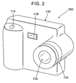
- the camera 100 according to the present invention is in the form of a digital camera which comprises a camera body 110 for use in recording a light beam from a subject to be photographed and an image taking system 120 for taking the image of the subject.
- the image taking system 120 may be of a structure that is removably mounted on the camera body 110.
- the image taking system 120 defines an optical axis 122 and comprises a taking-lens optical system 124, a diaphragm 126, a shutter 127, a focusing mechanism 172 for moving part or the whole of the lenses in the taking-lens optical system 124 to focus an image defined by the light beam from the subject onto a focal plane, a shutter actuating mechanism 173 for actuating the shutter 127, and a diaphragm actuating mechanism 174 for actuating the diaphragm 126.
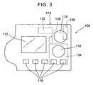
- the camera body 110 includes a finder 112, a shutter button 114, one or more switches (five switches being shown in Fig. 3) 116, one or more dials 118 (two dials being shown in Fig. 3) and a flash lamp 119.
- the finder 112 can comprise a liquid crystal display (LCD).
- the camera body 110 also includes a CCD sensor 130 for receiving the image defined by the focused light beam from the subject passing through the taking-lens optical system 124, an integrated circuit (IC) 132 including a CPU for processing information relating to the light beam from the subject received by the CCD sensor 130 and a RAM card 134 for storing the information of the light beam from the subject that is processed by the CPU.
- IC integrated circuit
- the RAM card 134 may be replaced by any one selected from a group consisting of a magnetic tape, a flexible disk, a CD-ROM, a CD-R, a CD-RW, a DVD-R, a DVD-RW, a DVD-RAM, a laser disk and a MO disk.
- the IC 132 may include a CPU, a ROM, a RAM and the like. ROM, RAM and the like may be provided separately from the IC 132. It is preferred that the IC 132 is in the form of a PLA-IC including a program for executing various instructions.
- the camera body 110 is also provided with a crystal oscillator 136 for generating a reference signal and a battery 138 serving as a power source. According to this embodiment of the present invention, furthermore, external components such as resistances, capacitors, coils, diodes, transistors may be used with the IC 132, if necessary.
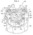
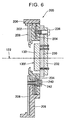
- the mount adjustment mechanism 200 is provided which can change an angular orientation of the image receiving portion in the CCD sensor 130 with respect to the optical axis 122 of the taking-lens optical system 124.
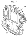
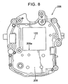
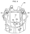
- the mount adjustment mechanism 200 comprises a mount 202 for supporting the CCD sensor 130, a rearward barrel 206, a steel ball 218 fixedly mounted on the mount 202 and movable adjuster means in the form of two threaded members 220, 222 disposed between the mount 202 and the rearward barrel 206.
- the rearward barrel 206 is located at a position rearwardmost of the taking lens barrel (i.e., a position farthermost from the subject in the taking lens barrel).
- the steel ball 218 defines a mount reference to be used in positioning the mount 202 in both the directions parallel and perpendicular to the optical axis 122.
- the mount reference is defined by a portion of the spherical surface of the steel ball 218.
- the steel ball 218 may be in the form of a stainless steel ball for use with a ball bearing.
- the steel ball 218 may be, for example, 3.4 mm in diameter.
- the steel ball 218 may be replaced by a metallic or plastic pin which has a hemispherical head and is fixedly mounted on the rearward barrel 206 or a hemispherical mount reference portion may be formed integrally with the rearward barrel 206, rather than the steel ball 218.
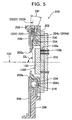
- a support plate 230 is disposed in intimate contact with the backside of the CCD sensor 130 (i.e., the side of the CCD sensor 130 opposite to the image receiving side 130f thereof for receiving the light beam from the subject).
- the support plate 230 may be formed of stainless steel.
- a CCD circuit board 232 for the CCD sensor 130 is disposed in intimate contact with the backside of the support plate 230 (i.e., the side of the support plate 230 opposite to the other side thereof on which the CCD sensor 130 is disposed).
- the CCD sensor 130 includes a plurality of terminals 130a which extend through apertures formed in the support plate 230 and CCD circuit board 232. The ends of the terminals 130a are soldered together to form a predetermined pattern in the CCD circuit board 232.
- the rearward barrel 206 uses a barrel insert 208 as a base, and is made by outsert molding an engineering plastic such as polycarbonate.
- the thickness of the barrel insert 208 may preferably be equal to, for example, 1 mm, taking the strength or the like into consideration.
- the barrel insert 208 includes a rectangular opening 208a formed therethrough which permits the passage of the light beam from the subject. Referring to Fig. 5, the steel ball 218 is adapted to be brought into contact with the barrel insert 208.
- the CCD circuit board 232 is fixedly threadedly attached to the mount 202 by means of circuit-board screws 236 after the CCD sensor 130 and support plate 230 are mounted on the CCD circuit board 232.
- the former is guided by guide pins 202f, 202g in the mount 202.
- the circuit-board screws 236 are passed into pilot holes 220c and 220d in the mount 202 by self-tapping.
- the mount 202 is fixedly mounted on the barrel insert 208 by passing mount screws 240 into tapped holes in the barrel insert 208. Referring to Fig.
- a mount pressing spring 242 is disposed between the underside of the head in each of the mount screws 240 and each bearing surface in the rearward barrel 206.
- each of the mount pressing springs 242 is in the form of a coil spring.
- Each of the mount pressing springs 242 serves as a resilient member for urging the mount 202 against the taking lens barrel (i.e., the rearward barrel 206).
- the first mount pressing spring 242 is preferably disposed close to the steel ball 218.
- the second mount pressing spring 242 is preferably disposed close to the adjusting screw 220. It is also preferred that the third mount pressing spring 242 is located close to the adjusting screw 222. While the embodiment of the present invention shown in Fig. 4 utilizes three mount screws 240 and three mount pressing springs 242, they may be four or more in number, respectively. In such an arrangement, the image pickup apparatus such as a camera can hold the CCD sensor 130 with increased reliability.
- the mount 202 uses a mount insert 204 as a base, and is made by insert molding an engineering plastic such as polycarbonate.
- the thickness of the mount insert 204 may preferably be equal to, for example, 0.6 mm.
- the mount 202 includes a rectangular opening 202a formed therethrough which permits the passage of the light beam from the subject.
- the mount insert 204 is formed with a steel ball contact portion 204b which is brought into contact with the steel ball 218.
- the steel ball contact portion 204b can be internally formed into a spherical shape complementary to the outline of the steel ball 218.
- the mount insert 204 can be formed with a first adjusting slope or inclined surface 204c to be brought into contact with the moving member or first adjusting screw 220.
- the mount insert can also be formed with a second adjusting slope 204d to be brought into contact with the second adjusting screw 222.
- the inclination of each of the adjusting slopes 204c, 204d is selected so that a portion of the adjusting slope close to the optical axis 122 is located close to the backside of the barrel insert 208 while another portion of the adjusting slope spaced apart from the optical axis 122 is positioned away from the backside of the barrel insert 208.
- An angle DP formed between the adjusting slope 204c and the backside of the barrel insert 208 is equal to, for example, 18.5 degrees.
- the angle DP is preferably in the range of 5 degrees to 45 degrees and more preferably between 10 degrees and 30 degrees.
- An angle DP formed between the adjusting slope 204d and the backside of the barrel insert 208 is equal to, for example, 18.5 degrees.
- the angle DP is preferably in the range of 5 degrees to 45 degrees and more preferably between 10 degrees and 30 degrees.
- the threaded adjuster member 220 is movable along a central axis 220X.
- the threaded adjuster member 222 is movable along a central axis 222X.
- the movable adjuster means of the mount adjusting mechanism can comprises the threaded adjuster members 220, 222.
- the central axis 222X is oriented non-parallel to the optical axis 122.
- the central axis 220X is oriented non-parallel to the optical axis 122.
- the central axis 220X is preferably positioned to intersect the optical axis 122. It is also preferred that the central axis 222X is arranged to intersect the optical axis 122. While the embodiment of the present invention shown in Fig. 4 has been described with respect to two threaded adjuster members 220, 222, the number of threaded adjuster members may be three or more.
- the threaded adjuster member 220 includes a main body 220b and a tip shank 220c.
- the main body 220b includes an external thread 220d formed thereon around the entire outer periphery thereof.
- the main body 220b serves as a "continuous thread screw”.
- the main body 220b also includes a hexagonal hole 220g formed in the top end 220f thereof.
- the threaded adjuster members 220, 222 are threaded into the tapped holes in the rearward barrel 206, respectively.
- the threaded adjuster member 220 When a hexagon wrench is engaged in the hexagonal hole 220g and then rotated, the threaded adjuster member 220 may be threaded into or unthreaded from the tapped hole of the rearward barrel 206.
- the external diameter of the tip shank 220c is configured to be smaller than the root diameter of the external thread 220d. It is preferred that the threaded adjuster member 222 has the same configuration as that of the threaded adjuster member 220.
- the angular orientation of the mount insert 204 with respect to the rearward barrel 206 can be changed by changing the depth to which the threaded adjuster member 220 is threaded into the tapped hole of the rearward barrel 206.
- the angular orientation of the mount insert 204 with respect to the rearward barrel 206 can be also changed by changing the depth to which the threaded adjuster member 222 is threaded into the tapped hole of the rearward barrel 206.
- the axial stroke ST in each of the threaded adjuster members 220, 222 may preferably be in the range of about 2 mm to about 3 mm. In such an arrangement, the threaded adjuster members 220, 222 can be turned without access from the side of eyepiece. Therefore, the tilt of the CCD sensor relative to the optical axis 122 can be adjusted in an extremely easy and simple manner.
- the mount insert 204 may be formed with no adjusting slope or inclined surface.
- the threaded adjuster member may have its tapered tip shank.
- the larger diameter of the tapered tip shank in the threaded adjuster member will be brought into contact with the mount insert 204.
- the inclination of the mount insert 204 relative to the rearward barrel 206 can be changed.
- an angle DL formed between the central axis 220X and the optical axis 122 is preferably in the range of 30 degrees to 150 degrees, more preferably 70 degrees to 110 degrees and most preferably equal to 90 degrees.
- An angle DL formed between the central axis 222X and the optical axis 122 is preferably in the range of 30 degrees to 150 degrees, more preferably 70 degrees to 110 degrees and most preferably equal to 90 degrees.
- the angle formed between the central axis 220X and the optical axis 122 is preferably equal to the angle formed between the central axis 222X and the optical axis 122.
- the tip end face of the threaded adjuster member 220 is configured to be brought into contact with the adjusting slope 204c in the mount insert 204.
- the tip end face of the threaded adjuster member 222 is configured to be brought into contact with the adjusting slope 204d in the mount insert 204.
- the lateral face of the threaded adjuster member 220 is configured to be brought into contact with the barrel insert 208.
- the side face of the threaded adjuster member 222 is configured to be brought into contact with the barrel insert 208.
- the center points of the tips of the threaded adjuster members 220 and 222 are positioned so as to define an "divergent angle" about the optical axis 122, which is preferably in the range of 30 degrees to 170 degrees, more preferably 90 degrees to 150 degrees and most preferably equal to 120 degrees.
- the term "divergent angle” herein indicates an angle DK formed between a perpendicular line extending from the center of the tip end of the threaded adjuster member 220 to the optical axis 122 and a perpendicular line extending from the center of the tip end of the threaded adjuster member 222 to the optical axis 122.
- the tilt of the CCD sensor 130 relative to the optical axis 122 can more precisely be adjusted in a stable and positive manner.
- the tilt of the CCD sensor 130 relative to the optical axis 122 can be adjusted more easily and simply.
- the mount adjustment mechanism 200 including the CCD sensor 130 is disposed rearwardmost of the taking lens barrel.
- the IC 132 comprises a mode storage section 132a for storing a mode set by a dial 118, an operation control section 132b for controlling the operation of the camera 100 on the actuation of the switch 116 and shutter button 114, a flash lamp control section 132c for controlling flash light from the flash lamp 119 based on a signal outputted by the operation control section 132b, an image information processing section 132e for processing information relating to an image formed by the light beam from the subject, based on a signal outputted from the CCD sensor 130 which has been actuated by the signal from the operation control section 132b, a shutter control section 132g for outputting a signal to the shutter actuating mechanism 173 to control the actuation of the shutter 127 based on the signal which is outputted by the image information processing section 132e, a display control section 132h for controlling indication based on the signal which is outputted by the image
- the operation control section 132b, flash lamp control section 132c, image information processing section 132e, shutter control section 132g, display control section 132h, focus detection control section 132j and diaphragm control section 132k may preferably be installed in the IC 132 as computer software.
- the respective operations and procedures of the operation control section 132b, flash lamp control section 132c, image information processing section 132e, shutter control section 132g, display control section 132h, focus detection control section 132j and diaphragm control section 132k are prepared into a program as computer software, such a program being then provided into the IC 132.
- the IC 132 is preferably in the form of a PLA-IC.
- Modes settable by the dial 118 may include, for example, a mode for setting whether or not the flash lamp 119 is actuated; a manual mode for manually setting the exposure (i.e., a so-called M mode); a mode for setting whether or not the diaphragm is to be made preferential (i.e., a so-called AV mode); a mode for setting whether or not the shutter speed is to be made preferential (i.e., a so-called TV mode); a program mode (i.e., a so-called P mode); an automatic focusing mode for automatically adjusting the focus (i.e., a so-called AF mode); a manual focusing mode (i.e., a so-called MF mode); a mode for determining whether the image storage medium is a RAM card or other storage medium and other modes.
- M mode a mode for setting whether or not the diaphragm is to be made preferential
- a mode for setting whether or not the shutter speed is to be made preferential
- the measuring terminals in the CCD circuit board 232 of the mount adjustment mechanism 200 are first connected to an image measuring device (not shown). Then, a test chart is taken by the camera 100. A light beam from the pattern in the test chart is received by the CCD sensor 130. A signal relating to the pattern of the test chart which has been received by the CCD sensor 130 is inputted into the image measuring device through the measuring terminals in the CCD circuit board 232. An operator then turns the threaded adjuster member 220 and 222 using the hexagon wrench while viewing the data inputted into the image measuring device.
- the mount adjustment mechanism can be adjusted by turning the threaded adjuster members 220 and 222 through access from a direction perpendicular to the optical axis, the manufacturing/adjusting process in the image pickup apparatus can be simplified.
- the dial 118 is first manipulated to set a desired operation mode in the camera 100.
- the dial 118 may be manipulated to set an operation mode in which the flash lamp 119 will not be lighted; the exposure being performed in the program mode; the focusing being automatically executed; and the image being recorded in the RAM card 134.
- the mode set as described is then stored in the mode storage section 132a.
- the CCD sensor 130 is actuated to receive the light beam from the subject by the signal outputted from the operation control section 132b.
- the image information processing section 132e then processes information relating to the image defined by the light beam from the subject, based on the signal outputted by the CCD sensor 130.
- the display control section 132h controls the contents of display based on the signal outputted by the image information processing section 132e.
- the image defined by the light beam from the subject is displayed on the finder 112 based on the signal outputted from the display control section 132h.
- the focus detection control section 132j receives the signal outputted from the image information processing section 132e and provides, based on the signal, a signal to the focusing mechanism 172 to focus the image formed by the light beam from the subject onto a focal plane. In such a manner, the focus detection control section 132j can control the operation of the focusing mechanism 172 by using such a signal.
- the focusing mechanism 172 moves part or the whole of the lenses in the taking-lens optical system 124 to focus the image defined by the light beam from the subject.
- the shutter control section 132g and diaphragm control section 132k respectively compute appropriate values of shutter speed and diaphragm stop which have been previously predetermined according to the program, based on the signal outputted by the image information processing section 132e.
- the diaphragm control section 132k receives the signal from the image information processing section 132e and provides, based on the signal, a signal to the diaphragm actuating mechanism 174 to actuate the diaphragm 126, so that the diaphragm 126 can be actuated to provide the computed diaphragm stop.
- the shutter control section 132g receives the signal from the image information processing section 132e and provides a signal to the shutter actuating mechanism 173 to actuate the shutter 127 at the computed shutter speed.
- the display control section 132h records the image defined by the light beam from the subject into the RAM card 134 with that shutter speed.
- the present invention can be applied to image pickup apparatuses such as digital cameras, monitor cameras and image readers.
Landscapes
- Engineering & Computer Science (AREA)
- Multimedia (AREA)
- Signal Processing (AREA)
- Physics & Mathematics (AREA)
- General Physics & Mathematics (AREA)
- Optics & Photonics (AREA)
- Studio Devices (AREA)
- Lens Barrels (AREA)
Applications Claiming Priority (2)
| Application Number | Priority Date | Filing Date | Title |
|---|---|---|---|
| JP2003347133A JP2005117253A (ja) | 2003-10-06 | 2003-10-06 | 撮像装置 |
| JP2003347133 | 2003-10-06 |
Publications (2)
| Publication Number | Publication Date |
|---|---|
| EP1522888A1 EP1522888A1 (en) | 2005-04-13 |
| EP1522888B1 true EP1522888B1 (en) | 2007-02-14 |
Family
ID=34309183
Family Applications (1)
| Application Number | Title | Priority Date | Filing Date |
|---|---|---|---|
| EP04256104A Expired - Lifetime EP1522888B1 (en) | 2003-10-06 | 2004-10-01 | Mount adjustment mechanism of the image sensor in an image pickup apparatus |
Country Status (6)
Families Citing this family (29)
| Publication number | Priority date | Publication date | Assignee | Title |
|---|---|---|---|---|
| JP4555732B2 (ja) * | 2005-05-24 | 2010-10-06 | オリンパスイメージング株式会社 | 撮像装置 |
| US7829833B2 (en) | 2005-05-24 | 2010-11-09 | Olympus Imaging Corp. | Arranging and/or supporting an image pickup device in an image pickup apparatus |
| JP3845446B1 (ja) * | 2005-08-11 | 2006-11-15 | 稔 稲葉 | ディジタルカメラ |
| KR100677627B1 (ko) * | 2006-01-06 | 2007-02-02 | 삼성전자주식회사 | 스캐닝 모듈 및 이를 구비한 화상독취장치 |
| JP2007189502A (ja) * | 2006-01-13 | 2007-07-26 | Matsushita Electric Ind Co Ltd | 撮像素子駆動装置およびそれを用いた撮影装置 |
| US20070236591A1 (en) * | 2006-04-11 | 2007-10-11 | Tam Samuel W | Method for mounting protective covers over image capture devices and devices manufactured thereby |
| DE102007004724A1 (de) * | 2007-01-22 | 2008-07-24 | Pilz Gmbh & Co. Kg | Kameraeinheit zum Überwachen eines Raumbereichs, insbesondere als Teil einer mitlaufenden Schutzeinrichtung an einem bewegten Maschinenteil |
| US8456560B2 (en) * | 2007-01-26 | 2013-06-04 | Digitaloptics Corporation | Wafer level camera module and method of manufacture |
| JP4953874B2 (ja) * | 2007-03-27 | 2012-06-13 | 株式会社リコー | レンズ鏡胴、撮像装置および情報端末装置 |
| CN101730863B (zh) * | 2007-04-24 | 2011-12-28 | 弗莱克斯电子有限责任公司 | 相机模块及其制造方法 |
| US7734171B2 (en) | 2008-01-29 | 2010-06-08 | Autoliv Asp, Inc. | Snap-in retainer for a sensor system |
| KR100969321B1 (ko) | 2008-07-21 | 2010-07-09 | 엘지전자 주식회사 | 카메라모듈의 스큐보정장치 |
| KR101022864B1 (ko) * | 2009-04-09 | 2011-03-16 | 삼성전기주식회사 | 카메라 모듈 |
| KR101038800B1 (ko) * | 2009-07-08 | 2011-06-03 | 삼성전기주식회사 | 카메라 모듈 |
| US9419032B2 (en) * | 2009-08-14 | 2016-08-16 | Nanchang O-Film Optoelectronics Technology Ltd | Wafer level camera module with molded housing and method of manufacturing |
| CN102056010A (zh) * | 2009-11-02 | 2011-05-11 | 鸿富锦精密工业(深圳)有限公司 | 笔记本电脑照相机功能自动测试系统及方法 |
| JP5574157B2 (ja) * | 2010-03-16 | 2014-08-20 | 株式会社リコー | 撮像装置の組み立て方法および撮像装置 |
| JP5771901B2 (ja) * | 2010-03-29 | 2015-09-02 | 株式会社リコー | 撮像装置 |
| CN102073119B (zh) * | 2010-12-24 | 2012-07-25 | 深圳市大族激光科技股份有限公司 | 一种透镜的定心调节镜架 |
| JP5830684B2 (ja) * | 2011-01-18 | 2015-12-09 | パナソニックIpマネジメント株式会社 | カメラ本体 |
| CN103091805A (zh) * | 2011-11-03 | 2013-05-08 | 华晶科技股份有限公司 | 镜头座、其制造方法及其影像撷取装置 |
| TWI444698B (zh) * | 2012-07-06 | 2014-07-11 | Altek Corp | 調校裝置及其調校方法 |
| CN103760655B (zh) * | 2014-01-23 | 2016-02-10 | 中国科学院上海光学精密机械研究所 | 大承载的二维角度调整机构 |
| DE102014211879A1 (de) * | 2014-06-20 | 2016-01-07 | Robert Bosch Gmbh | Verfahren zum Herstellen einer Kamera und Kamera für ein Fahrzeug |
| US9621874B2 (en) * | 2014-08-29 | 2017-04-11 | Delphi Technologies, Inc. | Multiple imager camera |
| DE102015117276B4 (de) | 2015-10-09 | 2018-09-06 | Carl Zeiss Industrielle Messtechnik Gmbh | Verfahren und Vorrichtung zum Vermessen eines Messobjekts mit verbesserter Messgenauigkeit |
| JP6738995B2 (ja) * | 2016-05-16 | 2020-08-12 | パナソニックIpマネジメント株式会社 | シャッターユニットおよび撮像装置 |
| DE102017000889A1 (de) * | 2017-01-27 | 2018-08-02 | Christian Overmann | Modulares optisches Aufnahmesystem |
| JP7313869B2 (ja) * | 2018-05-11 | 2023-07-25 | キヤノン株式会社 | 撮像装置、制御装置、制御方法及びプログラム |
Family Cites Families (11)
| Publication number | Priority date | Publication date | Assignee | Title |
|---|---|---|---|---|
| JPS61118707A (ja) * | 1984-11-15 | 1986-06-06 | Matsushita Electric Ind Co Ltd | 固体撮像装置 |
| JPS6242678A (ja) * | 1985-08-09 | 1987-02-24 | Olympus Optical Co Ltd | 固体撮像装置 |
| JP3466763B2 (ja) * | 1995-03-13 | 2003-11-17 | キヤノン株式会社 | 撮像装置 |
| US6351288B1 (en) * | 1997-06-27 | 2002-02-26 | Eastman Kodak Company | Sensor tilt control for a digital camera |
| KR200171652Y1 (ko) * | 1998-01-24 | 2000-04-01 | 권태웅 | 고체 촬상소자 카메라의 초점 조절장치 |
| JP2000010141A (ja) * | 1998-06-26 | 2000-01-14 | Ricoh Co Ltd | 手振れ補正機能付きデジタルカメラ |
| US6628339B1 (en) * | 1999-06-14 | 2003-09-30 | Eastman Kodak Company | Image sensor mount for a digital camera |
| JP3592645B2 (ja) * | 2001-02-16 | 2004-11-24 | 中央精機株式会社 | 光学部材支持機構 |
| JP4739560B2 (ja) * | 2001-03-29 | 2011-08-03 | リコー光学株式会社 | マルチビーム光源ユニット及びこれを有する光走査装置 |
| JP3766618B2 (ja) * | 2001-08-29 | 2006-04-12 | ペンタックス株式会社 | 固体撮像素子の取付構造 |
| US6710945B1 (en) * | 2002-06-03 | 2004-03-23 | Amkor Technology, Inc. | Injection molded lens-barrel assembly and method for fabricating lens-barrel and mount assemblies |
-
2003
- 2003-10-06 JP JP2003347133A patent/JP2005117253A/ja active Pending
-
2004
- 2004-10-01 EP EP04256104A patent/EP1522888B1/en not_active Expired - Lifetime
- 2004-10-01 DE DE602004004719T patent/DE602004004719T2/de not_active Expired - Fee Related
- 2004-10-06 KR KR1020040079700A patent/KR100688752B1/ko not_active Expired - Fee Related
- 2004-10-06 US US10/958,342 patent/US7532247B2/en not_active Expired - Fee Related
- 2004-10-08 CN CNB2004100807093A patent/CN100445859C/zh not_active Expired - Fee Related
Also Published As
| Publication number | Publication date |
|---|---|
| CN100445859C (zh) | 2008-12-24 |
| DE602004004719D1 (de) | 2007-03-29 |
| KR20050033495A (ko) | 2005-04-12 |
| KR100688752B1 (ko) | 2007-02-28 |
| JP2005117253A (ja) | 2005-04-28 |
| CN1605922A (zh) | 2005-04-13 |
| US20050073602A1 (en) | 2005-04-07 |
| US7532247B2 (en) | 2009-05-12 |
| EP1522888A1 (en) | 2005-04-13 |
| DE602004004719T2 (de) | 2007-06-14 |
Similar Documents
| Publication | Publication Date | Title |
|---|---|---|
| EP1522888B1 (en) | Mount adjustment mechanism of the image sensor in an image pickup apparatus | |
| US7586700B2 (en) | Method for adjusting optical axis of imaging optical system and lens system | |
| US7499230B2 (en) | Lens barrel, lens tilt adjusting method and imaging apparatus | |
| WO2007066578A1 (ja) | デジタルカメラ | |
| US4924247A (en) | Apparatus and method for correcting and adjusting parallax in electronic camera | |
| US20090002826A1 (en) | Lens barrel | |
| JP4893633B2 (ja) | レンズ鏡胴及び撮像装置 | |
| JP2009302837A (ja) | 撮像素子の位置調整方法、カメラモジュール製造方法及び装置 | |
| US20030043287A1 (en) | Three-dimensional image capturing device | |
| JP5295304B2 (ja) | 撮像装置 | |
| JPH08304917A (ja) | スチルカメラ一体型ビデオカメラ | |
| JP2008090180A (ja) | 撮像装置 | |
| JP4194449B2 (ja) | 固体撮像素子の保持構造 | |
| JP6062196B2 (ja) | レンズユニット及びこれを具えた撮像装置 | |
| JP3044688B2 (ja) | カメラの制御方法 | |
| JP2005142837A (ja) | カメラの調整装置 | |
| JP5585199B2 (ja) | レンズ鏡筒及び撮像装置 | |
| US7301861B2 (en) | Coma aberration correcting apparatus for optical pickup | |
| JP2006126441A (ja) | 焦点検出モジュールの取付構造および焦点検出モジュールを有する光学機器 | |
| JP2008278124A (ja) | 撮像素子のアオリ調整方法及び該方法で調整された撮像素子を有するカメラ機器 | |
| JP2002072058A (ja) | カメラの調整装置及びその調整方法 | |
| JP2000267155A (ja) | カメラ | |
| JP2006139097A (ja) | 光学系の検査装置及び検査方法 | |
| KR20090070527A (ko) | 디지털 촬영장치, 그 제어방법 및 제어방법을 실행시키기위한 프로그램을 저장한 기록매체 | |
| JPH09231632A (ja) | 光磁気ヘッド位置合わせ装置 |
Legal Events
| Date | Code | Title | Description |
|---|---|---|---|
| PUAI | Public reference made under article 153(3) epc to a published international application that has entered the european phase |
Free format text: ORIGINAL CODE: 0009012 |
|
| 17P | Request for examination filed |
Effective date: 20041018 |
|
| AK | Designated contracting states |
Kind code of ref document: A1 Designated state(s): AT BE BG CH CY CZ DE DK EE ES FI FR GB GR HU IE IT LI LU MC NL PL PT RO SE SI SK TR |
|
| AX | Request for extension of the european patent |
Extension state: AL HR LT LV MK |
|
| AKX | Designation fees paid |
Designated state(s): DE FR GB |
|
| GRAP | Despatch of communication of intention to grant a patent |
Free format text: ORIGINAL CODE: EPIDOSNIGR1 |
|
| GRAS | Grant fee paid |
Free format text: ORIGINAL CODE: EPIDOSNIGR3 |
|
| GRAA | (expected) grant |
Free format text: ORIGINAL CODE: 0009210 |
|
| AK | Designated contracting states |
Kind code of ref document: B1 Designated state(s): DE FR GB |
|
| REG | Reference to a national code |
Ref country code: GB Ref legal event code: FG4D |
|
| REF | Corresponds to: |
Ref document number: 602004004719 Country of ref document: DE Date of ref document: 20070329 Kind code of ref document: P |
|
| ET | Fr: translation filed | ||
| PLBE | No opposition filed within time limit |
Free format text: ORIGINAL CODE: 0009261 |
|
| STAA | Information on the status of an ep patent application or granted ep patent |
Free format text: STATUS: NO OPPOSITION FILED WITHIN TIME LIMIT |
|
| 26N | No opposition filed |
Effective date: 20071115 |
|
| PGFP | Annual fee paid to national office [announced via postgrant information from national office to epo] |
Ref country code: FR Payment date: 20080818 Year of fee payment: 5 |
|
| PGFP | Annual fee paid to national office [announced via postgrant information from national office to epo] |
Ref country code: DE Payment date: 20081105 Year of fee payment: 5 |
|
| PGFP | Annual fee paid to national office [announced via postgrant information from national office to epo] |
Ref country code: GB Payment date: 20081001 Year of fee payment: 5 |
|
| REG | Reference to a national code |
Ref country code: FR Ref legal event code: ST Effective date: 20100630 |
|
| PG25 | Lapsed in a contracting state [announced via postgrant information from national office to epo] |
Ref country code: FR Free format text: LAPSE BECAUSE OF NON-PAYMENT OF DUE FEES Effective date: 20091102 Ref country code: DE Free format text: LAPSE BECAUSE OF NON-PAYMENT OF DUE FEES Effective date: 20100501 |
|
| PG25 | Lapsed in a contracting state [announced via postgrant information from national office to epo] |
Ref country code: GB Free format text: LAPSE BECAUSE OF NON-PAYMENT OF DUE FEES Effective date: 20091001 |