EP1521870B2 - Dispositif pour guider, traiter ou transporter au moins un fil - Google Patents
Dispositif pour guider, traiter ou transporter au moins un fil Download PDFInfo
- Publication number
- EP1521870B2 EP1521870B2 EP03738025.0A EP03738025A EP1521870B2 EP 1521870 B2 EP1521870 B2 EP 1521870B2 EP 03738025 A EP03738025 A EP 03738025A EP 1521870 B2 EP1521870 B2 EP 1521870B2
- Authority
- EP
- European Patent Office
- Prior art keywords
- roll
- asynchronous motor
- companion
- delivery
- motor
- Prior art date
- Legal status (The legal status is an assumption and is not a legal conclusion. Google has not performed a legal analysis and makes no representation as to the accuracy of the status listed.)
- Expired - Lifetime
Links
- 238000010438 heat treatment Methods 0.000 claims description 4
- 230000011664 signaling Effects 0.000 claims 1
- 230000002093 peripheral effect Effects 0.000 description 15
- 230000006698 induction Effects 0.000 description 5
- 230000000694 effects Effects 0.000 description 4
- 230000008901 benefit Effects 0.000 description 3
- 230000008859 change Effects 0.000 description 3
- 230000003993 interaction Effects 0.000 description 2
- 230000006978 adaptation Effects 0.000 description 1
- 230000001276 controlling effect Effects 0.000 description 1
- 230000001419 dependent effect Effects 0.000 description 1
- 230000001105 regulatory effect Effects 0.000 description 1
- 238000009987 spinning Methods 0.000 description 1
- 230000008093 supporting effect Effects 0.000 description 1
- 230000001360 synchronised effect Effects 0.000 description 1
- 230000007704 transition Effects 0.000 description 1
Images

Classifications
-
- D—TEXTILES; PAPER
- D01—NATURAL OR MAN-MADE THREADS OR FIBRES; SPINNING
- D01D—MECHANICAL METHODS OR APPARATUS IN THE MANUFACTURE OF ARTIFICIAL FILAMENTS, THREADS, FIBRES, BRISTLES OR RIBBONS
- D01D5/00—Formation of filaments, threads, or the like
- D01D5/12—Stretch-spinning methods
- D01D5/16—Stretch-spinning methods using rollers, or like mechanical devices, e.g. snubbing pins
-
- B—PERFORMING OPERATIONS; TRANSPORTING
- B65—CONVEYING; PACKING; STORING; HANDLING THIN OR FILAMENTARY MATERIAL
- B65H—HANDLING THIN OR FILAMENTARY MATERIAL, e.g. SHEETS, WEBS, CABLES
- B65H51/00—Forwarding filamentary material
- B65H51/30—Devices controlling the forwarding speed to synchronise with supply, treatment, or take-up apparatus
-
- B—PERFORMING OPERATIONS; TRANSPORTING
- B65—CONVEYING; PACKING; STORING; HANDLING THIN OR FILAMENTARY MATERIAL
- B65H—HANDLING THIN OR FILAMENTARY MATERIAL, e.g. SHEETS, WEBS, CABLES
- B65H59/00—Adjusting or controlling tension in filamentary material, e.g. for preventing snarling; Applications of tension indicators
- B65H59/38—Adjusting or controlling tension in filamentary material, e.g. for preventing snarling; Applications of tension indicators by regulating speed of driving mechanism of unwinding, paying-out, forwarding, winding, or depositing devices, e.g. automatically in response to variations in tension
- B65H59/384—Adjusting or controlling tension in filamentary material, e.g. for preventing snarling; Applications of tension indicators by regulating speed of driving mechanism of unwinding, paying-out, forwarding, winding, or depositing devices, e.g. automatically in response to variations in tension using electronic means
- B65H59/388—Regulating forwarding speed
-
- D—TEXTILES; PAPER
- D02—YARNS; MECHANICAL FINISHING OF YARNS OR ROPES; WARPING OR BEAMING
- D02J—FINISHING OR DRESSING OF FILAMENTS, YARNS, THREADS, CORDS, ROPES OR THE LIKE
- D02J13/00—Heating or cooling the yarn, thread, cord, rope, or the like, not specific to any one of the processes provided for in this subclass
- D02J13/005—Heating or cooling the yarn, thread, cord, rope, or the like, not specific to any one of the processes provided for in this subclass by contact with at least one rotating roll
-
- B—PERFORMING OPERATIONS; TRANSPORTING
- B65—CONVEYING; PACKING; STORING; HANDLING THIN OR FILAMENTARY MATERIAL
- B65H—HANDLING THIN OR FILAMENTARY MATERIAL, e.g. SHEETS, WEBS, CABLES
- B65H2701/00—Handled material; Storage means
- B65H2701/30—Handled filamentary material
- B65H2701/31—Textiles threads or artificial strands of filaments
Definitions
- the invention relates to a device for guiding, treating or conveying at least one thread according to the preamble of claim 1.
- the delivery roller and the auxiliary role are each driven by an electric motor designed as a synchronous motor.
- the electric motors are controlled by a control unit by a target frequency to drive each of the delivery and the Beilaufrolle with the same peripheral speed.
- the design of the drives is based on the fact that in order to maintain as constant a thread speed as possible, the peripheral speed of the delivery roller and the peripheral speed of the auxiliary roller must be kept constant. In practice, however, even slight inaccuracies in the mantle of the delivery roll or in the mantle of the loose roll lead to deviations in the jacket diameters, which has an immediate effect on a change in the peripheral speeds. This effect causes the thread at the circumference of the axler be either braked or fed with a flow. However, such interactions lead to a troubled threadline, which has a negative effect especially in the leadership of several parallel running parallel threads.
- the invention is therefore based on the object, a device of the type mentioned in such a way that the thread can be performed at the periphery of the supply roll and on the circumference of the Beilaufrolle at a substantially constant speed.
- the electric motor of the by-pass roller is designed as an asynchronous motor which is controlled by a nominal frequency and which has a motor slip.
- the invention has the particular advantage that the fan-out roller can be operated at a speed which is based on the actual peripheral speed of the delivery roller.
- the electric motor of the delivery roller is also designed as an asynchronous motor, which, however, has a control feedback.
- the sensor is supplied with a sensor which serves to measure an actual frequency. Via a signal line, the actual frequency is supplied to the control unit, in which a correction of the desired frequency takes place. Since both the asynchronous motor of the delivery roller and the asynchronous motor of the by-pass roller are controlled by the reference frequency of the control unit, the change in the nominal frequency is also abandoned analogously to the asynchronous motor of the supplementary role.
- This has the particular advantage that, when loaded, the asynchronous motors can be operated with a tendency to have the same field orientation, so that the flywheel has a supporting effect on the delivery roller in order to apply a total traction.
- the asynchronous motor of the by-pass roller is designed to be as electrically soft as possible, ie. H. the asynchronous motor of the auxiliary role has a relatively large engine slippage.
- the asynchronous motor of the delivery roller is executed with the lowest possible engine slip.
- the supply roll and the auxiliary roll can have a substantially equal coat diameter.
- the by-pass roller is formed with a much smaller sheath diameter.
- the asynchronous motor of the Beilaufrolle is designed with a smaller number of pole pairs to convert the target frequency in a corresponding peripheral speed.
- the delivery roller and / or the accompanying roller have at least one diameter step.
- This embodiment is particularly advantageous, for example, to carry out a swirling of the thread within a preferably last looping of the thread between the delivery roller and the loose roll.
- the supply roll and / or the auxiliary roll could have at least one conical jacket region.
- the supply roll is preferably made with a heating means, so that the jacket of the supply roll has a temperature required for the treatment of the yarn.
- the setting has proved successful, in which the peripheral speed of the The idler pulley of the asynchronous motor is 0.1 - 10% above the peripheral speed of the delivery roller.
- the peripheral speed of the The idler pulley of the asynchronous motor is 0.1 - 10% above the peripheral speed of the delivery roller.
- Fig. 1 schematically a view of a first embodiment of the device according to the invention is shown.
- the device has a delivery roller 2 and an enclosed at a distance from the delivery roller 2 arranged Beilaufrolle 3.
- the delivery roller 2 is rotatably mounted projecting on a support 4.1 and connected by a drive shaft 5 with an electric motor 7.
- the electric motor 7 of the delivery roller 2 is designed as an asynchronous motor.
- the asynchronous motor 7 is coupled to the control unit 10 via the control line 9.1.
- a sensor 11 for detecting an actual frequency of the asynchronous motor 7 is provided at the asynchronous motor 7 is provided.
- the sensor 11 is connected by the signal line 12 to the controller 10.
- the Beilaufrolle 3 is cantilevered on the support 4.2 and is driven by the electric motor 8 via the drive shaft 6.
- the electric motor 8 of the auxiliary role 3 is designed as an asynchronous motor.
- the asynchronous motor 8 is connected via the control line 9.2 with the control unit 10.
- Fig. 1 If the device according to the invention is shown in an operating state. In this case, a thread 1 is guided in several wraps on the supply roller 2 and the Beilaufrolle 3. In this embodiment, only one thread is shown. However, the device according to the invention is preferably used to guide a plurality of parallel threads 1. For example, to draw the yarn from a spinneret or to draw in a draw zone, the supply roll 2 and the follower roll 3 are driven at substantially the same peripheral speed. For this purpose, the asynchronous motor 7 of the delivery roller 2 is controlled by the control unit 10 with a predetermined desired frequency.
- the actual frequency is detected by the sensor 11 with the asynchronous motor 7 of the delivery roller and fed to the control unit 10 through the signal line 12.
- the delivery roller 2 is driven at a predetermined target speed, which is independent of the engine slip of the induction motor 7 ..
- the drive of the Beilaufrolle 3 by the induction motor 8 is carried out with identical nominal frequency, which is given by the control unit 10 via the control line 9.2 the induction motor 8.
- the asynchronous motor 8 has compared to the asynchronous motor 7 of the delivery roller a smaller number of pole pairs, which is selected according to the diameter ratios of the sheath diameter of the delivery roller 2 and the sheath diameter of the Beilaufrolle 3.
- the asynchronous motor 8 of the fan-out roller 3 is particularly electrically soft and thus has a relatively high engine slippage.
- the actual peripheral speed of the flywheel 3 adapts to the respective load state, so that no undesired interactions are produced on the thread 1 between the delivery roller 2 and the slip roller 3.
- the uncontrolled peripheral speed of the by-pass roller 3 thus substantially equals the regulated peripheral speed of the delivery roller 2.
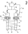
- Fig. 2 is another example of such a device shown schematically.
- the example in Fig. 2 is substantially identical to the previous embodiment according to Fig. 1 , so that reference is made to the preceding description and only the differences are shown below.
- the components with the same function have been given identical reference numerals.
- asynchronous motor 7 of the supply roller 2 and the asynchronous motor 8 of the fly-by roller 3 are formed identically, since the supply roller 2 and the Beilaufrolle 3 have a same size shell diameter.
- the control of the asynchronous motor 7 for driving the supply roller 2 and the control of the asynchronous motor 8 of the auxiliary pulley 3 is identical to the previous embodiment.
- Each of the asynchronous motors 7 and 8 are controlled with a set by the control unit 10 target frequency, wherein the target frequency in the control unit 10 according to the actual frequency of the induction motor 7 of the delivery roller 2 is determined and specified.
- the supply roller 2 in the example after Fig. 2 executed with a diameter level 13.
- the axler 3 does not contain a diameter step.
- a differential speed which leads to a thread tension relief in the thread 1.
- This can be used, for example, advantageously to swirl the thread 1 between the delivery roller 2 and the Beilaufrolle 3.
- Fig. 2 a Verwirbelungsdüse 14 shown in dashed lines.
Claims (6)
- Dispositif pour guider, traiter ou avancer au moins un fil (1) avec un rouleau d'alimentation (2) et avec un rouleau accompagnateur (3) coopérant avec le rouleau d'alimentation (2), le fil (1) enlaçant de façon multiple le rouleau d'alimentation (2) et le rouleau accompagnateur (3), avec un moteur électrique (7) associé au rouleau d'alimentation (2), avec un deuxième moteur électrique (8) associé au rouleau accompagnateur (3) et avec un appareil de commande (10) qui est relié aux moteurs électriques (7, 8) au moyen de lignes de commande (9.1, 9.2) et qui commande les moteurs électriques (7, 8) avec une fréquence désirée, caractérisé en ce que le moteur électrique (8) du rouleau accompagnateur (3) est réalisé comme un moteur asynchrone qui est commandé par la fréquence désirée et qui a un glissement de moteur, le moteur électrique (7) du rouleau d'alimentation (2) étant réalisé comme un moteur asynchrone et le moteur asynchrone (7) du rouleau d'alimentation (2) ayant un capteur (11) pour mesurer une fréquence réelle, laquelle fréquence réelle est fournie via une ligne de signalisation (12) à l'appareil de commande (10) pour corriger la fréquence désirée, le moteur asynchrone (8) du rouleau accompagnateur (3) ayant un glissement du moteur sensiblement plus élevé que le moteur asynchrone (7) du rouleau d'alimentation (2) et la commande du moteur asynchrone (8) du rouleau accompagnateur (3) étant effectuée sans rétroaction de réglage.
- Dispositif selon la revendication 1, caractérisé en ce que le rouleau d'alimentation (2) et le rouleau accompagnateur (3) ont chacun un diamètre d'enveloppe, ce qui permet de définir un rapport de diamètres et en ce que les moteurs asynchrones (7, 8) ont chacun un nombre de paires de pôles, grâce auxquelles un rapport de paires de pôles peut être défini, et en ce que le rapport de diamètres entre le rouleau d'alimentation (2) et le rouleau accompagnateur (3) est égal au rapport entre des paires de pôles du moteur asynchrone (7) du rouleau d'alimentation (2) et le moteur asynchrone (8) du rouleau accompagnateur (3).
- Dispositif selon l'une quelconque des revendications 1 à 2, caractérisé en ce que le rouleau d'alimentation (2) et/ou le rouleau accompagnateur (3) ont au moins un échelon de diamètre (13) dans l'enveloppe.
- Dispositif selon l'une quelconque des revendications 1 à 3, caractérisé en ce que le rouleau d'alimentation (2) et/ou le rouleau accompagnateur (3) ont au moins une région d'enveloppe conique.
- Dispositif selon l'une quelconque des revendications 1 à 4, caractérisé en ce que le rouleau d'alimentation (2) et/ou le rouleau accompagnateur (3) ont un moyen de chauffage pour chauffer l'enveloppe.
- Dispositif selon l'une quelconque des revendications 1 à 5, caractérisé en ce que le rouleau accompagnateur est configuré de préférence de telle manière que sa vitesse circonférentielle dans la marche à vide du moteur asynchrone est de 0,1 - 10 % au dessus de la vitesse circonférentielle du rouleau d'alimentation.
Applications Claiming Priority (3)
| Application Number | Priority Date | Filing Date | Title |
|---|---|---|---|
| DE10227290A DE10227290A1 (de) | 2002-06-19 | 2002-06-19 | Vorrichtung zum Führen, Behandeln und Fördern von zumindest einem Faden |
| DE10227290 | 2002-06-19 | ||
| PCT/EP2003/006231 WO2004001106A1 (fr) | 2002-06-19 | 2003-06-13 | Dispositif pour guider, traiter ou transporter au moins un fil |
Publications (3)
| Publication Number | Publication Date |
|---|---|
| EP1521870A1 EP1521870A1 (fr) | 2005-04-13 |
| EP1521870B1 EP1521870B1 (fr) | 2007-05-09 |
| EP1521870B2 true EP1521870B2 (fr) | 2013-05-08 |
Family
ID=29719239
Family Applications (1)
| Application Number | Title | Priority Date | Filing Date |
|---|---|---|---|
| EP03738025.0A Expired - Lifetime EP1521870B2 (fr) | 2002-06-19 | 2003-06-13 | Dispositif pour guider, traiter ou transporter au moins un fil |
Country Status (6)
| Country | Link |
|---|---|
| US (1) | US7226286B2 (fr) |
| EP (1) | EP1521870B2 (fr) |
| JP (1) | JP4263691B2 (fr) |
| CN (1) | CN100359052C (fr) |
| DE (2) | DE10227290A1 (fr) |
| WO (1) | WO2004001106A1 (fr) |
Families Citing this family (10)
| Publication number | Priority date | Publication date | Assignee | Title |
|---|---|---|---|---|
| DE10343460A1 (de) * | 2002-10-04 | 2004-04-15 | Saurer Gmbh & Co. Kg | Vorrichtung zum Spinnen und Aufwickeln zumindest eines synthetischen Fadens |
| DE102005030280B3 (de) * | 2005-06-29 | 2006-09-28 | Aradex Ag | Verfahren zum Betrieb einer bahnverarbeitenden Maschine |
| DE102005045496A1 (de) * | 2005-09-23 | 2007-03-29 | Saurer Gmbh & Co. Kg | Vorrichtung zum Schmelzspinnen und Abziehen eines Fadens |
| EP2463417B1 (fr) * | 2010-12-13 | 2013-07-10 | Oerlikon Textile GmbH & Co. KG | Unité de galettes |
| DE102011102560A1 (de) | 2011-05-26 | 2012-11-29 | Oerlikon Textile Gmbh & Co. Kg | Vorrichtung zum Abziehen und Verstrecken eines synthetischen Fadens |
| DE102011109784A1 (de) | 2011-08-08 | 2013-02-14 | Oerlikon Textile Gmbh & Co. Kg | Vorrichtung zum Schmelzspinnen, Abziehen, Verstrecken, Relaxieren und Aufwickeln eines synthetischen Fadens |
| CN103320882B (zh) * | 2012-03-22 | 2016-02-24 | 中国纺织科学研究院 | 一种纤维萃取装置和纤维多级萃取装置 |
| CN106081738A (zh) * | 2016-07-28 | 2016-11-09 | 吴江金叶织造有限公司 | 纱线张力机构 |
| CN206469676U (zh) * | 2017-01-19 | 2017-09-05 | 深圳市众耀光电有限公司 | 一种led灯带的加工设备 |
| DE102020006542A1 (de) * | 2020-10-24 | 2022-04-28 | Oerlikon Textile Gmbh & Co. Kg | Verfahren zur Drehzahlregelung von Galetten und Vorrichtung zum Führen, Verstrecken und / oder Relaxieren von Fäden |
Family Cites Families (15)
| Publication number | Priority date | Publication date | Assignee | Title |
|---|---|---|---|---|
| US3576081A (en) * | 1969-12-17 | 1971-04-27 | William G Mccrary | Combination strand-drying and bearing-lubrication apparatus |
| JPS5917460A (ja) * | 1982-07-20 | 1984-01-28 | Toray Ind Inc | 糸条物の送行処理ロ−ラ |
| DE3613040A1 (de) * | 1986-04-17 | 1987-10-22 | Barmag Barmer Maschf | Fadenabzuggeraet |
| DE3704279A1 (de) * | 1986-02-20 | 1987-09-17 | Barmag Barmer Maschf | Verfahren zur drehzahlregelung bei individuell angetriebenen fadenlieferwerken |
| EP0726338B1 (fr) * | 1995-02-10 | 2001-11-28 | B a r m a g AG | Procédé de fabrication d'un fil multifilament |
| JP2982733B2 (ja) * | 1997-02-26 | 1999-11-29 | 村田機械株式会社 | 紡糸巻取機の巻取制御装置 |
| DE19832811A1 (de) * | 1997-07-26 | 1999-01-28 | Barmag Barmer Maschf | Verfahren zum Aufwickeln eines Fadens |
| DE19733239A1 (de) * | 1997-08-01 | 1999-02-04 | Elektrische Automatisierungs U | Antrieb und Lagerung von Galetten |
| DE19849007A1 (de) * | 1997-10-31 | 1999-05-20 | Barmag Barmer Maschf | Verfahren zum Aufspulen eines laufenden Fadens |
| TW518376B (en) * | 1998-03-05 | 2003-01-21 | Barmag Barmer Maschf | Method and apparatus for spinning, drawing, and winding a yarn |
| DE19916607A1 (de) * | 1998-04-15 | 1999-10-21 | Barmag Barmer Maschf | Verfahren zur Drehzahlregelung bei einem Lieferwerk |
| DE19843990C1 (de) * | 1998-09-25 | 1999-08-19 | Dienes Apparatebau Gmbh | Integriertes Galettenaggregat |
| JP2000152679A (ja) * | 1998-11-10 | 2000-05-30 | Murata Mach Ltd | モータ制御装置及び制御方法 |
| DE19916669A1 (de) * | 1999-04-14 | 2000-11-02 | Stahlecker Fritz | Vorrichtung zum Aufspulen von Fäden auf Spulen mit wilder Kreuzwicklung |
| DE10207086A1 (de) * | 2002-02-20 | 2003-08-28 | Barmag Barmer Maschf | Texturiermaschine |
-
2002
- 2002-06-19 DE DE10227290A patent/DE10227290A1/de not_active Withdrawn
-
2003
- 2003-06-13 JP JP2004514710A patent/JP4263691B2/ja not_active Expired - Fee Related
- 2003-06-13 DE DE50307248T patent/DE50307248D1/de not_active Expired - Lifetime
- 2003-06-13 EP EP03738025.0A patent/EP1521870B2/fr not_active Expired - Lifetime
- 2003-06-13 WO PCT/EP2003/006231 patent/WO2004001106A1/fr active IP Right Grant
- 2003-06-13 CN CNB038141132A patent/CN100359052C/zh not_active Expired - Fee Related
-
2004
- 2004-11-24 US US10/997,839 patent/US7226286B2/en not_active Expired - Fee Related
Also Published As
| Publication number | Publication date |
|---|---|
| DE50307248D1 (de) | 2007-06-21 |
| DE10227290A1 (de) | 2004-01-08 |
| JP2005530057A (ja) | 2005-10-06 |
| US7226286B2 (en) | 2007-06-05 |
| CN100359052C (zh) | 2008-01-02 |
| EP1521870A1 (fr) | 2005-04-13 |
| EP1521870B1 (fr) | 2007-05-09 |
| JP4263691B2 (ja) | 2009-05-13 |
| WO2004001106A1 (fr) | 2003-12-31 |
| CN1662687A (zh) | 2005-08-31 |
| US20050071968A1 (en) | 2005-04-07 |
Similar Documents
| Publication | Publication Date | Title |
|---|---|---|
| EP1178139B1 (fr) | Machine de texturation par fausse torsion | |
| DE2118775A1 (de) | Verfahren und Vorrichtung zum Antreiben einer offenendigen Spinnmaschine | |
| EP1521870B2 (fr) | Dispositif pour guider, traiter ou transporter au moins un fil | |
| EP1238273B1 (fr) | Procede pour commander une machine a texturer, et machine a texturer | |
| DE2508896C3 (de) | Verfahren zum Verseilen mehrerer Adern zu einem elektrischen Kabel | |
| DE19809875A1 (de) | Vorrichtung zum Zuführen von Faserbändern an Streckwerken von Spinnereimaschinen, insbesondere von Strecken | |
| DE3519301A1 (de) | Vorrichtung mit mindestens einer spulstelle zum herstellen der wicklung einer kreuzspule | |
| DE3218471C2 (de) | Vorrichtung zur Herstellung eines Effektgarnes | |
| EP1673494A1 (fr) | Dispositif pour guider, acheminer ou traiter un cable de fibres | |
| DE102013000824A1 (de) | Aufspulmaschine | |
| DE2812100A1 (de) | Verfahren zum parallelfuehren eines zusammengesetzten stranges und vorrichtung zur durchfuehrung des verfahrens | |
| DE69813122T2 (de) | Mehrfach-Zwirnmaschine | |
| DE4126392C1 (en) | Appts. for spooling up fibres, preventing slippage and power fluctuations - includes controlling spooling speed by regulating spool spindle revolutions acccording to contact roller speed | |
| CH695316A5 (de) | Vorrichtung zum Zuführen von Faserbändern an einer Spinnereimaschine. | |
| DE19916607A1 (de) | Verfahren zur Drehzahlregelung bei einem Lieferwerk | |
| DE2644673A1 (de) | Verfahren und vorrichtung zur behandlung eines garnes | |
| DE2117093A1 (de) | Kabelverseilvorrichtung | |
| DE3147163C2 (de) | Vorrichtung zur Fadenzuführung zum Maschenbildungssystem einer Wirkmaschine | |
| WO2002068834A1 (fr) | Rouleau pour guider au moins un fil | |
| WO2002052078A1 (fr) | Ensemble galette et dispositif pour etirer un fil | |
| DE3704279C2 (fr) | ||
| DE19635373C2 (de) | Vorrichtung zum Ausgleichen von Fadenverbrauchs- und Fadenspannungsschwankungen bei der Zuführung von fadenförmigem Material | |
| EP1520825B1 (fr) | Procédé et dispositif pour la régulation de la tension du fil sur un bobinoir et l'utilisation du procédé | |
| EP0512257B1 (fr) | Procédé et dispositif pour contrôler la vitesse de rotation des broches d'un métier à retordre | |
| DE2251843A1 (de) | Streckzwirnmaschine |
Legal Events
| Date | Code | Title | Description |
|---|---|---|---|
| PUAI | Public reference made under article 153(3) epc to a published international application that has entered the european phase |
Free format text: ORIGINAL CODE: 0009012 |
|
| 17P | Request for examination filed |
Effective date: 20050114 |
|
| AK | Designated contracting states |
Kind code of ref document: A1 Designated state(s): AT BE BG CH CY CZ DE DK EE ES FI FR GB GR HU IE IT LI LU MC NL PT RO SE SI SK TR |
|
| AX | Request for extension of the european patent |
Extension state: AL LT LV MK |
|
| DAX | Request for extension of the european patent (deleted) | ||
| RBV | Designated contracting states (corrected) |
Designated state(s): CH DE IT LI |
|
| GRAP | Despatch of communication of intention to grant a patent |
Free format text: ORIGINAL CODE: EPIDOSNIGR1 |
|
| GRAS | Grant fee paid |
Free format text: ORIGINAL CODE: EPIDOSNIGR3 |
|
| GRAA | (expected) grant |
Free format text: ORIGINAL CODE: 0009210 |
|
| AK | Designated contracting states |
Kind code of ref document: B1 Designated state(s): CH DE IT LI |
|
| REG | Reference to a national code |
Ref country code: CH Ref legal event code: EP |
|
| REF | Corresponds to: |
Ref document number: 50307248 Country of ref document: DE Date of ref document: 20070621 Kind code of ref document: P |
|
| RAP2 | Party data changed (patent owner data changed or rights of a patent transferred) |
Owner name: OERLIKON TEXTILE GMBH & CO. KG |
|
| PLBI | Opposition filed |
Free format text: ORIGINAL CODE: 0009260 |
|
| 26 | Opposition filed |
Opponent name: MASCHINENFABRIK RIETER AG / SWISSTEX WINTERTHUR AG Effective date: 20080204 |
|
| PLAX | Notice of opposition and request to file observation + time limit sent |
Free format text: ORIGINAL CODE: EPIDOSNOBS2 |
|
| PLBB | Reply of patent proprietor to notice(s) of opposition received |
Free format text: ORIGINAL CODE: EPIDOSNOBS3 |
|
| RAP2 | Party data changed (patent owner data changed or rights of a patent transferred) |
Owner name: OERLIKON TEXTILE GMBH & CO. KG |
|
| PUAH | Patent maintained in amended form |
Free format text: ORIGINAL CODE: 0009272 |
|
| STAA | Information on the status of an ep patent application or granted ep patent |
Free format text: STATUS: PATENT MAINTAINED AS AMENDED |
|
| 27A | Patent maintained in amended form |
Effective date: 20130508 |
|
| AK | Designated contracting states |
Kind code of ref document: B2 Designated state(s): CH DE IT LI |
|
| REG | Reference to a national code |
Ref country code: CH Ref legal event code: AELC |
|
| REG | Reference to a national code |
Ref country code: DE Ref legal event code: R102 Ref document number: 50307248 Country of ref document: DE Effective date: 20130508 |
|
| PGFP | Annual fee paid to national office [announced via postgrant information from national office to epo] |
Ref country code: IT Payment date: 20140618 Year of fee payment: 12 |
|
| PGFP | Annual fee paid to national office [announced via postgrant information from national office to epo] |
Ref country code: DE Payment date: 20140701 Year of fee payment: 12 Ref country code: CH Payment date: 20140708 Year of fee payment: 12 |
|
| REG | Reference to a national code |
Ref country code: DE Ref legal event code: R119 Ref document number: 50307248 Country of ref document: DE |
|
| PG25 | Lapsed in a contracting state [announced via postgrant information from national office to epo] |
Ref country code: IT Free format text: LAPSE BECAUSE OF NON-PAYMENT OF DUE FEES Effective date: 20150613 |
|
| REG | Reference to a national code |
Ref country code: CH Ref legal event code: PL |
|
| PG25 | Lapsed in a contracting state [announced via postgrant information from national office to epo] |
Ref country code: DE Free format text: LAPSE BECAUSE OF NON-PAYMENT OF DUE FEES Effective date: 20160101 Ref country code: LI Free format text: LAPSE BECAUSE OF NON-PAYMENT OF DUE FEES Effective date: 20150630 Ref country code: CH Free format text: LAPSE BECAUSE OF NON-PAYMENT OF DUE FEES Effective date: 20150630 |