EP1521870B2 - Device for guiding, treating, or conveying at least one thread - Google Patents
Device for guiding, treating, or conveying at least one thread Download PDFInfo
- Publication number
- EP1521870B2 EP1521870B2 EP03738025.0A EP03738025A EP1521870B2 EP 1521870 B2 EP1521870 B2 EP 1521870B2 EP 03738025 A EP03738025 A EP 03738025A EP 1521870 B2 EP1521870 B2 EP 1521870B2
- Authority
- EP
- European Patent Office
- Prior art keywords
- roll
- asynchronous motor
- companion
- delivery
- motor
- Prior art date
- Legal status (The legal status is an assumption and is not a legal conclusion. Google has not performed a legal analysis and makes no representation as to the accuracy of the status listed.)
- Expired - Lifetime
Links
- 238000010438 heat treatment Methods 0.000 claims description 4
- 230000011664 signaling Effects 0.000 claims 1
- 230000002093 peripheral effect Effects 0.000 description 15
- 230000006698 induction Effects 0.000 description 5
- 230000000694 effects Effects 0.000 description 4
- 230000008901 benefit Effects 0.000 description 3
- 230000008859 change Effects 0.000 description 3
- 230000003993 interaction Effects 0.000 description 2
- 230000006978 adaptation Effects 0.000 description 1
- 230000001276 controlling effect Effects 0.000 description 1
- 230000001419 dependent effect Effects 0.000 description 1
- 230000001105 regulatory effect Effects 0.000 description 1
- 238000009987 spinning Methods 0.000 description 1
- 230000008093 supporting effect Effects 0.000 description 1
- 230000001360 synchronised effect Effects 0.000 description 1
- 230000007704 transition Effects 0.000 description 1
Images

Classifications
-
- D—TEXTILES; PAPER
- D01—NATURAL OR MAN-MADE THREADS OR FIBRES; SPINNING
- D01D—MECHANICAL METHODS OR APPARATUS IN THE MANUFACTURE OF ARTIFICIAL FILAMENTS, THREADS, FIBRES, BRISTLES OR RIBBONS
- D01D5/00—Formation of filaments, threads, or the like
- D01D5/12—Stretch-spinning methods
- D01D5/16—Stretch-spinning methods using rollers, or like mechanical devices, e.g. snubbing pins
-
- B—PERFORMING OPERATIONS; TRANSPORTING
- B65—CONVEYING; PACKING; STORING; HANDLING THIN OR FILAMENTARY MATERIAL
- B65H—HANDLING THIN OR FILAMENTARY MATERIAL, e.g. SHEETS, WEBS, CABLES
- B65H51/00—Forwarding filamentary material
- B65H51/30—Devices controlling the forwarding speed to synchronise with supply, treatment, or take-up apparatus
-
- B—PERFORMING OPERATIONS; TRANSPORTING
- B65—CONVEYING; PACKING; STORING; HANDLING THIN OR FILAMENTARY MATERIAL
- B65H—HANDLING THIN OR FILAMENTARY MATERIAL, e.g. SHEETS, WEBS, CABLES
- B65H59/00—Adjusting or controlling tension in filamentary material, e.g. for preventing snarling; Applications of tension indicators
- B65H59/38—Adjusting or controlling tension in filamentary material, e.g. for preventing snarling; Applications of tension indicators by regulating speed of driving mechanism of unwinding, paying-out, forwarding, winding, or depositing devices, e.g. automatically in response to variations in tension
- B65H59/384—Adjusting or controlling tension in filamentary material, e.g. for preventing snarling; Applications of tension indicators by regulating speed of driving mechanism of unwinding, paying-out, forwarding, winding, or depositing devices, e.g. automatically in response to variations in tension using electronic means
- B65H59/388—Regulating forwarding speed
-
- D—TEXTILES; PAPER
- D02—YARNS; MECHANICAL FINISHING OF YARNS OR ROPES; WARPING OR BEAMING
- D02J—FINISHING OR DRESSING OF FILAMENTS, YARNS, THREADS, CORDS, ROPES OR THE LIKE
- D02J13/00—Heating or cooling the yarn, thread, cord, rope, or the like, not specific to any one of the processes provided for in this subclass
- D02J13/005—Heating or cooling the yarn, thread, cord, rope, or the like, not specific to any one of the processes provided for in this subclass by contact with at least one rotating roll
-
- B—PERFORMING OPERATIONS; TRANSPORTING
- B65—CONVEYING; PACKING; STORING; HANDLING THIN OR FILAMENTARY MATERIAL
- B65H—HANDLING THIN OR FILAMENTARY MATERIAL, e.g. SHEETS, WEBS, CABLES
- B65H2701/00—Handled material; Storage means
- B65H2701/30—Handled filamentary material
- B65H2701/31—Textiles threads or artificial strands of filaments
Definitions
- the invention relates to a device for guiding, treating or conveying at least one thread according to the preamble of claim 1.
- the delivery roller and the auxiliary role are each driven by an electric motor designed as a synchronous motor.
- the electric motors are controlled by a control unit by a target frequency to drive each of the delivery and the Beilaufrolle with the same peripheral speed.
- the design of the drives is based on the fact that in order to maintain as constant a thread speed as possible, the peripheral speed of the delivery roller and the peripheral speed of the auxiliary roller must be kept constant. In practice, however, even slight inaccuracies in the mantle of the delivery roll or in the mantle of the loose roll lead to deviations in the jacket diameters, which has an immediate effect on a change in the peripheral speeds. This effect causes the thread at the circumference of the axler be either braked or fed with a flow. However, such interactions lead to a troubled threadline, which has a negative effect especially in the leadership of several parallel running parallel threads.
- the invention is therefore based on the object, a device of the type mentioned in such a way that the thread can be performed at the periphery of the supply roll and on the circumference of the Beilaufrolle at a substantially constant speed.
- the electric motor of the by-pass roller is designed as an asynchronous motor which is controlled by a nominal frequency and which has a motor slip.
- the invention has the particular advantage that the fan-out roller can be operated at a speed which is based on the actual peripheral speed of the delivery roller.
- the electric motor of the delivery roller is also designed as an asynchronous motor, which, however, has a control feedback.
- the sensor is supplied with a sensor which serves to measure an actual frequency. Via a signal line, the actual frequency is supplied to the control unit, in which a correction of the desired frequency takes place. Since both the asynchronous motor of the delivery roller and the asynchronous motor of the by-pass roller are controlled by the reference frequency of the control unit, the change in the nominal frequency is also abandoned analogously to the asynchronous motor of the supplementary role.
- This has the particular advantage that, when loaded, the asynchronous motors can be operated with a tendency to have the same field orientation, so that the flywheel has a supporting effect on the delivery roller in order to apply a total traction.
- the asynchronous motor of the by-pass roller is designed to be as electrically soft as possible, ie. H. the asynchronous motor of the auxiliary role has a relatively large engine slippage.
- the asynchronous motor of the delivery roller is executed with the lowest possible engine slip.
- the supply roll and the auxiliary roll can have a substantially equal coat diameter.
- the by-pass roller is formed with a much smaller sheath diameter.
- the asynchronous motor of the Beilaufrolle is designed with a smaller number of pole pairs to convert the target frequency in a corresponding peripheral speed.
- the delivery roller and / or the accompanying roller have at least one diameter step.
- This embodiment is particularly advantageous, for example, to carry out a swirling of the thread within a preferably last looping of the thread between the delivery roller and the loose roll.
- the supply roll and / or the auxiliary roll could have at least one conical jacket region.
- the supply roll is preferably made with a heating means, so that the jacket of the supply roll has a temperature required for the treatment of the yarn.
- the setting has proved successful, in which the peripheral speed of the The idler pulley of the asynchronous motor is 0.1 - 10% above the peripheral speed of the delivery roller.
- the peripheral speed of the The idler pulley of the asynchronous motor is 0.1 - 10% above the peripheral speed of the delivery roller.
- Fig. 1 schematically a view of a first embodiment of the device according to the invention is shown.
- the device has a delivery roller 2 and an enclosed at a distance from the delivery roller 2 arranged Beilaufrolle 3.
- the delivery roller 2 is rotatably mounted projecting on a support 4.1 and connected by a drive shaft 5 with an electric motor 7.
- the electric motor 7 of the delivery roller 2 is designed as an asynchronous motor.
- the asynchronous motor 7 is coupled to the control unit 10 via the control line 9.1.
- a sensor 11 for detecting an actual frequency of the asynchronous motor 7 is provided at the asynchronous motor 7 is provided.
- the sensor 11 is connected by the signal line 12 to the controller 10.
- the Beilaufrolle 3 is cantilevered on the support 4.2 and is driven by the electric motor 8 via the drive shaft 6.
- the electric motor 8 of the auxiliary role 3 is designed as an asynchronous motor.
- the asynchronous motor 8 is connected via the control line 9.2 with the control unit 10.
- Fig. 1 If the device according to the invention is shown in an operating state. In this case, a thread 1 is guided in several wraps on the supply roller 2 and the Beilaufrolle 3. In this embodiment, only one thread is shown. However, the device according to the invention is preferably used to guide a plurality of parallel threads 1. For example, to draw the yarn from a spinneret or to draw in a draw zone, the supply roll 2 and the follower roll 3 are driven at substantially the same peripheral speed. For this purpose, the asynchronous motor 7 of the delivery roller 2 is controlled by the control unit 10 with a predetermined desired frequency.
- the actual frequency is detected by the sensor 11 with the asynchronous motor 7 of the delivery roller and fed to the control unit 10 through the signal line 12.
- the delivery roller 2 is driven at a predetermined target speed, which is independent of the engine slip of the induction motor 7 ..
- the drive of the Beilaufrolle 3 by the induction motor 8 is carried out with identical nominal frequency, which is given by the control unit 10 via the control line 9.2 the induction motor 8.
- the asynchronous motor 8 has compared to the asynchronous motor 7 of the delivery roller a smaller number of pole pairs, which is selected according to the diameter ratios of the sheath diameter of the delivery roller 2 and the sheath diameter of the Beilaufrolle 3.
- the asynchronous motor 8 of the fan-out roller 3 is particularly electrically soft and thus has a relatively high engine slippage.
- the actual peripheral speed of the flywheel 3 adapts to the respective load state, so that no undesired interactions are produced on the thread 1 between the delivery roller 2 and the slip roller 3.
- the uncontrolled peripheral speed of the by-pass roller 3 thus substantially equals the regulated peripheral speed of the delivery roller 2.
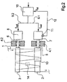
- Fig. 2 is another example of such a device shown schematically.
- the example in Fig. 2 is substantially identical to the previous embodiment according to Fig. 1 , so that reference is made to the preceding description and only the differences are shown below.
- the components with the same function have been given identical reference numerals.
- asynchronous motor 7 of the supply roller 2 and the asynchronous motor 8 of the fly-by roller 3 are formed identically, since the supply roller 2 and the Beilaufrolle 3 have a same size shell diameter.
- the control of the asynchronous motor 7 for driving the supply roller 2 and the control of the asynchronous motor 8 of the auxiliary pulley 3 is identical to the previous embodiment.
- Each of the asynchronous motors 7 and 8 are controlled with a set by the control unit 10 target frequency, wherein the target frequency in the control unit 10 according to the actual frequency of the induction motor 7 of the delivery roller 2 is determined and specified.
- the supply roller 2 in the example after Fig. 2 executed with a diameter level 13.
- the axler 3 does not contain a diameter step.
- a differential speed which leads to a thread tension relief in the thread 1.
- This can be used, for example, advantageously to swirl the thread 1 between the delivery roller 2 and the Beilaufrolle 3.
- Fig. 2 a Verwirbelungsdüse 14 shown in dashed lines.
Description
Die Erfindung betrifft eine Vorrichtung zum Führen, Behandeln oder Fördern von zumindest einem Faden gemäß dem Oberbegriff des Anspruchs 1.The invention relates to a device for guiding, treating or conveying at least one thread according to the preamble of claim 1.
Es ist bekannt, dass zur Führung und Förderung eines Fadens beispielsweise in einem Spinnprozeß derartige Vorrichtungen eingesetzt werden, die aus einer Lieferrolle und einer der Lieferrolle zugeordnete Beilaufrolle bestehen, um eine Mehrfachumschlingung des Fadens zu ermöglichen. Hierbei ist die Lieferrolle angetrieben, die Beilaufrolle kann mit oder ohne einen Antrieb ausgeführt sein, wie beispielsweise in der
Aus der
Der Erfindung liegt demnach die Aufgabe zugrunde, eine Vorrichtung der eingangs genannten Art derart auszubilden, dass der Faden am Umfang der Lieferrolle und am Umfang der Beilaufrolle mit im wesentlichen konstanter Geschwindigkeit geführt werden kann.The invention is therefore based on the object, a device of the type mentioned in such a way that the thread can be performed at the periphery of the supply roll and on the circumference of the Beilaufrolle at a substantially constant speed.
Diese Aufgabe wird erfindungsgemäß so gelöst, dass der Elektromotor der Beilaufrolle als ein Asynchronmotor ausgebildet ist, welcher durch eine Sollfrequenz gesteuert ist und welcher einen Motorschlupf aufweist. Die Erfindung besitzt den besonderen Vorteil, dass die Beilaufrolle mit einer Drehzahl betrieben werden kann, welche sich an der tatsächlichen Umfangsgeschwindigkeit der Lieferrolle orientiert. Durch die Steuerung des Asynchronmotors der Beilaufrolle ohne jeglicher Regelrückführung wird erreicht, dass durch den lastabhängigen Motorschlupf des Asynchronmotors am Umfang der Beilaufrolle sich eine Umfangsgeschwindigkeit einstellt, die im wesentlichen durch die Geschwindigkeit des Fadens und damit der Umfangsgeschwindigkeit der Lieferrolle bestimmt ist.This object is achieved in accordance with the invention such that the electric motor of the by-pass roller is designed as an asynchronous motor which is controlled by a nominal frequency and which has a motor slip. The invention has the particular advantage that the fan-out roller can be operated at a speed which is based on the actual peripheral speed of the delivery roller. By controlling the asynchronous motor of the Beilaufrolle without any rule feedback is achieved that adjusts by the load-dependent engine slip of the induction motor on the circumference of the Beilaufrolle a peripheral speed, which is determined essentially by the speed of the thread and thus the peripheral speed of the delivery role.
Dabei ist der Elektromotor der Lieferrolle ebenfalls als ein Asynchronmotor ausgebildet, welcher jedoch über eine Regelrückführung verfügt. Hierzu ist dem Asynchronmotor der Lieferrolle ein Sensor beigefügt, der zur Messung einer Istfrequenz dient. Über eine Signalleitung wird die Istfrequenz dem Steuergerät zugeführt, in welchem eine Korrektur der Soll-Frequenz erfolgt. Da sowohl der Asynchronmotor der Lieferrolle als auch der Asynchronmotor der Beilaufrolle durch die Sollfrequenz des Steuergerätes gesteuert werden, wird die Veränderung der Sollfrequenz analog auch den Asynchronmotor der Beilaufrolle aufgegeben. Dies hat den besonderen Vorteil, dass bei Belastung die Asynchronmotoren mit tendenziell gleicher Feldorientierung betrieben werden könne, so dass die Beilaufrolle unterstützend zu der Lieferrolle wirkt, um eine Gesamtzugkraft aufzubringen.In this case, the electric motor of the delivery roller is also designed as an asynchronous motor, which, however, has a control feedback. For this purpose, the sensor is supplied with a sensor which serves to measure an actual frequency. Via a signal line, the actual frequency is supplied to the control unit, in which a correction of the desired frequency takes place. Since both the asynchronous motor of the delivery roller and the asynchronous motor of the by-pass roller are controlled by the reference frequency of the control unit, the change in the nominal frequency is also abandoned analogously to the asynchronous motor of the supplementary role. This has the particular advantage that, when loaded, the asynchronous motors can be operated with a tendency to have the same field orientation, so that the flywheel has a supporting effect on the delivery roller in order to apply a total traction.
Um eine möglichst hohe Anpassung der Umfangsgeschwindigkeiten zu erhalten, wird gemäß der Erfindung der Asynchronmotor der Beilaufrolle möglichst elektrisch weich ausgelegt, d. h. der Asynchronmotor der Beilaufrolle weist einen relativ großen Motorschlupf auf. Demgegenüber wird der Asynchronmotor der Lieferrolle mit möglichst geringem Motorschlupf ausgeführt.In order to obtain the highest possible adaptation of the peripheral speeds, according to the invention, the asynchronous motor of the by-pass roller is designed to be as electrically soft as possible, ie. H. the asynchronous motor of the auxiliary role has a relatively large engine slippage. In contrast, the asynchronous motor of the delivery roller is executed with the lowest possible engine slip.
Die Lieferrolle und die Beilaufrolle können einen im wesentlichen gleich großen Manteldurchmesser aufweisen. Bevorzugt wird die Beilaufrolle jedoch mit einem wesentlich kleineren Manteldurchmesser ausgebildet. Hierzu ist der Asynchronmotor der Beilaufrolle mit einer geringeren Anzahl von Polpaaren ausgeführt, um die Sollfrequenz in eine entsprechende Umfangsgeschwindigkeit umzusetzen. Durch Einhaltung einer Beziehung, bei welcher das Durchmesserverhältnis von Lieferrolle zu Beilaufrolle gleich dem Polpaarverhältnis von Asynchronmotor der Lieferrolle zum Asynchronmotor der Beilaufrolle ist, können beliebige Durchmesserdifferenzen in der Lieferrolle und der Beilaufrolle ausgebildet sein.The supply roll and the auxiliary roll can have a substantially equal coat diameter. Preferably, however, the by-pass roller is formed with a much smaller sheath diameter. For this purpose, the asynchronous motor of the Beilaufrolle is designed with a smaller number of pole pairs to convert the target frequency in a corresponding peripheral speed. By maintaining a relationship in which the diameter ratio of the supply roller to the auxiliary pulley is equal to the pole pair ratio of the asynchronous motor of the supply pulley to the asynchronous motor of the pulley, arbitrary diameter differences can be formed in the supply pulley and the pulley.
Es besteht jedoch auch die Möglichkeit, bewusst Fadenspannungsänderungen in den Umschlingungen des Fadens zwischen der Lieferrolle und der Beilaufrolle einzustellen. Hierzu weist die Lieferrolle und / oder die Beilaufrolle zumindest eine Durchmesserstufe auf. Diese Ausbildung ist besonders vorteilhaft, um beispielsweise eine Verwirbelung des Fadens innerhalb einer bevorzugt letzten Umschlingung des Fadens zwischen der Lieferrolle und der Beilaufrolle vorzunehmen.However, it is also possible to consciously adjust thread tension changes in the wraps of the thread between the supply roll and the auxiliary roll. For this purpose, the delivery roller and / or the accompanying roller have at least one diameter step. This embodiment is particularly advantageous, for example, to carry out a swirling of the thread within a preferably last looping of the thread between the delivery roller and the loose roll.
Um eine stetige Veränderung der Fadenspannung zu erhalten, könne die Lieferrolle und / oder die Beilaufrolle zumindest einen konischen Mantelbereich aufweisen.In order to obtain a continuous change in the thread tension, the supply roll and / or the auxiliary roll could have at least one conical jacket region.
Zur Erwärmung des Fadens wird bevorzugt die Lieferrolle mit einem Heizmittel ausgeführt, so dass der Mantel der Lieferrolle eine zur Behandlung des Fadens erforderliche Temperatur aufweist.For heating the yarn, the supply roll is preferably made with a heating means, so that the jacket of the supply roll has a temperature required for the treatment of the yarn.
Um den Schlupf des Asynchronmotors der Beilaufrolle besser auszunutzen, hat sich die Einstellung bewährt, bei welcher die Umfangsgeschwindigkeit der Beilaufrolle im Leerlauf des Asynchronmotors um 0,1 - 10 % oberhalb der Umfangsgeschwindigkeit der Lieferrolle liegt. Dadurch kann vorteilhaft ein Bremseffekt der Fäden an der Beilaufrolle genutzt werden.In order to make better use of the slip of the asynchronous motor of the auxiliary pulley, the setting has proved successful, in which the peripheral speed of the The idler pulley of the asynchronous motor is 0.1 - 10% above the peripheral speed of the delivery roller. As a result, it is advantageous to use a braking effect of the threads on the auxiliary roll.
Weitere Vorteile der Erfindung sind im folgenden anhand eines Ausführungsbeispiels einer erfindungsgemäßen Vorrichtung unter Hinweis auf die beigefügten Zeichnungen näher beschrieben.Further advantages of the invention are described below with reference to an embodiment of a device according to the invention with reference to the accompanying drawings.
Es stellen dar:
- Fig. 1
- schematisch ein erstes Ausführungsbeispiel der erfindungsgemäßen Vorrichtung
- Fig. 2
- schematisch ein weiteres Beispiel einer solchen Vorrichtung
- Fig. 1
- schematically a first embodiment of the device according to the invention
- Fig. 2
- schematically another example of such a device
In
Die Beilaufrolle 3 ist an dem Träger 4.2 auskragend gelagert und wird über die Antriebswelle 6 von dem Elektromotor 8 angetrieben. Der Elektromotor 8 der Beilaufrolle 3 ist als Asynchronmotor ausgeführt. Der Asynchronmotor 8 ist über die Steuerleitung 9.2 mit dem Steuergerät 10 verbunden.The Beilaufrolle 3 is cantilevered on the support 4.2 and is driven by the
In
Der Antrieb der Beilaufrolle 3 durch den Asynchronmotor 8 erfolgt mit identischer Sollfrequenz, die durch das Steuergerät 10 über die Steuerleitung 9.2 dem Asynchronmotor 8 aufgegeben wird. Der Asynchronmotor 8 besitzt gegenüber dem Asynchronmotor 7 der Lieferrolle eine geringere Anzahl der Polpaare, die entsprechend der Durchmesserverhältnisse des Manteldurchmessers der Lieferrolle 2 und des Manteldurchmessers der Beilaufrolle 3 gewählt ist. Der Asynchronmotor 8 der Beilaufrolle 3 ist besonders elektrisch weich ausgebildet und weist somit einen relativ hohen Motorschlupf auf. Somit paßt sich die Ist-Umfangsgeschwindigkeit der Beilaufrolle 3 aufgrund des hohen Motorschlupfes des Asynchronmotors 8 dem jeweiligen Belastungszustand an, so dass keine unerwünschten Wechselwirkungen an dem Faden 1 zwischen der Lieferrolle 2 und der Beilaufrolle 3 erzeugt werden. Die ungeregelte Umfangsgeschwindigkeit der Beilaufrolle 3 gleicht sich somit im wesentlichen der geregelten Umfangsgeschwindigkeit der Lieferrolle 2 an.The drive of the
In
Zum Antrieb der Lieferrolle 2 und der Beilaufrolle 3 werden die als Asynchronmotoren ausgebildeten Elektromotoren 7 und 8 eingesetzt. Der Asynchronmotor 7 der Lieferrolle 2 und der Asynchronmotor 8 der Beilaufrolle 3 sind identisch ausgebildet, da die Lieferrolle 2 und die Beilaufrolle 3 einen gleich großen Manteldurchmesser aufweisen. Die Regelung des Asynchronmotors 7 zum Antreiben der Lieferrolle 2 und die Steuerung des Asynchronmotors 8 der Beilaufrolle 3 ist identisch zu dem vorhergehenden Ausführungsbeispiel. Jede der Asynchronmotoren 7 und 8 werden mit einer durch das Steuergerät 10 aufgegebenen Soll-Frequenz gesteuert, wobei die Sollfrequenz im Steuergerät 10 entsprechend der Istfrequenz des Asynchronmotors 7 der Lieferrolle 2 bestimmt und vorgegeben wird.To drive the
Gegenüber dem vorhergehenden Ausführungsbeispiel ist die Lieferrolle 2 bei dem Beispiel nach
- 11
- Fadenthread
- 22
- Lieferrolledelivery roll
- 33
- Beilaufrollecompanion roll
- 4.1, 4.24.1, 4.2
- Trägercarrier
- 55
- Antriebswelle der LieferrolleDrive shaft of the delivery roller
- 66
- Antriebswelle der BeilaufrolleDrive shaft of the by-pass roller
- 77
- Elektromotor der LieferrolleElectric motor of delivery roll
- 88th
- Elektromotor der BeilaufrolleElectric motor of the supplementary role
- 9.1, 9.29.1, 9.2
- Steuerleitungcontrol line
- 1010
- Steuergerätcontrol unit
- 1111
- Sensorsensor
- 1212
- Signalleitungsignal line
- 1313
- DurchmesserstufeDiameter step
- 1414
- Verwirbelungsdüseswirl jet
Claims (6)
- Device for guiding, treating, or advancing at least one yarn (1), comprising a delivery roll (2) and a companion roll (3) cooperating with the delivery roll (2), with the yarn (1) repeatedly looping the delivery roll (2) and the companion roll (3), comprising an electric motor (7) associated with the delivery roll (2), comprising a second electric motor (8) associated with the companion roll (3), and comprising a controller (10) that is connected by means of control lines (9.1, 9.2) to the electric motors (7, 8), and which controls the electric motors (7, 8) at a desired frequency, characterized in that the electric motor (8) of the companion roll (3) is designed as an asynchronous motor that is controlled by the desired frequency, and which has a motor slip, wherein the electric motor (7) of the delivery roll (2) is designed as an asynchronous motor, and wherein the asynchronous motor (7) of the delivery roll (2) includes a sensor (11) for measuring an actual frequency, which actual frequency is supplied via a signaling line (12) to the controller (10) for correcting the desired frequency, wherein the asynchronous motor (8) of the companion roll (3) has a substantially greater motor slip than the asynchronous motor (7) of the delivery roll (2), and wherein the asynchronous motor (8) of the companion roll (3) is controlled without any control feedback.
- Device of Claim 1, characterized in that the delivery roll (2) and the companion roll (3) have each a casing diameter, which permit defining a diameter ratio, and that the asynchronous motors (7, 8) have each a number of pole pairs, which permit defining a pole pair ratio, and that the ratio of the diameter of delivery roll (2) to the diameter of companion roll (3) equals the ratio of the pole pairs in the asynchronous motor (7) of the delivery roll (2) to the pole pairs in the asynchronous motor (8) of the companion roll (3).
- Device of either of Claims 1 and 2, characterized in that the delivery roll (2) and/or the companion roll (3) include at least one diametrical step (13) in the casing.
- Device of one of Claims 1-3, characterized in that the delivery roll (2) and/or the companion roll (3) include at least one conical section in the casing.
- Device of one of Claims 1-4, characterized in that the delivery roll (2) and/or the companion roll (3) include a heating means for heating the casing.
- Device of one of Claims 1-5, characterized in that the companion roll is preferably designed such that its circumferential speed in the noload operation of the asynchronous motor is 0.1-10% above the circumferential speed of the delivery roll.
Applications Claiming Priority (3)
| Application Number | Priority Date | Filing Date | Title |
|---|---|---|---|
| DE10227290 | 2002-06-19 | ||
| DE10227290A DE10227290A1 (en) | 2002-06-19 | 2002-06-19 | Device for guiding, treating and conveying at least one thread |
| PCT/EP2003/006231 WO2004001106A1 (en) | 2002-06-19 | 2003-06-13 | Device for guiding, treating, or conveying at least one thread |
Publications (3)
| Publication Number | Publication Date |
|---|---|
| EP1521870A1 EP1521870A1 (en) | 2005-04-13 |
| EP1521870B1 EP1521870B1 (en) | 2007-05-09 |
| EP1521870B2 true EP1521870B2 (en) | 2013-05-08 |
Family
ID=29719239
Family Applications (1)
| Application Number | Title | Priority Date | Filing Date |
|---|---|---|---|
| EP03738025.0A Expired - Lifetime EP1521870B2 (en) | 2002-06-19 | 2003-06-13 | Device for guiding, treating, or conveying at least one thread |
Country Status (6)
| Country | Link |
|---|---|
| US (1) | US7226286B2 (en) |
| EP (1) | EP1521870B2 (en) |
| JP (1) | JP4263691B2 (en) |
| CN (1) | CN100359052C (en) |
| DE (2) | DE10227290A1 (en) |
| WO (1) | WO2004001106A1 (en) |
Families Citing this family (10)
| Publication number | Priority date | Publication date | Assignee | Title |
|---|---|---|---|---|
| DE10343460A1 (en) * | 2002-10-04 | 2004-04-15 | Saurer Gmbh & Co. Kg | Roller drive for synthetic fiber spinning uses individual frequency controlled motors with one motor operating at a controlled speed slip |
| DE102005030280B3 (en) * | 2005-06-29 | 2006-09-28 | Aradex Ag | Operating a continuous sheet-processing machine, e.g. a printing machine, using process variables determined by measuring changes in influencing variables caused by modulating drive speeds for processing elements |
| DE102005045496A1 (en) * | 2005-09-23 | 2007-03-29 | Saurer Gmbh & Co. Kg | Apparatus for melt spinning and taking off synthetic thread, includes easily controlled drive for take-off and stretching reels based on electric motor and electric brake coordinated with respective reels |
| EP2463417B1 (en) * | 2010-12-13 | 2013-07-10 | Oerlikon Textile GmbH & Co. KG | Godet unit |
| DE102011102560A1 (en) | 2011-05-26 | 2012-11-29 | Oerlikon Textile Gmbh & Co. Kg | Apparatus for stripping and drawing a synthetic thread |
| DE102011109784A1 (en) | 2011-08-08 | 2013-02-14 | Oerlikon Textile Gmbh & Co. Kg | Apparatus for melt spinning, stripping, stretching, relaxing and winding a synthetic thread |
| CN103320882B (en) * | 2012-03-22 | 2016-02-24 | 中国纺织科学研究院 | A kind of fibre abstraction device and fiber multitple extraction device |
| CN106081738A (en) * | 2016-07-28 | 2016-11-09 | 吴江金叶织造有限公司 | Yarn tension mechanism |
| CN206469676U (en) * | 2017-01-19 | 2017-09-05 | 深圳市众耀光电有限公司 | A kind of process equipment of LED |
| DE102020006542A1 (en) * | 2020-10-24 | 2022-04-28 | Oerlikon Textile Gmbh & Co. Kg | Method for controlling the speed of godets and device for guiding, stretching and/or relaxing threads |
Family Cites Families (15)
| Publication number | Priority date | Publication date | Assignee | Title |
|---|---|---|---|---|
| US3576081A (en) * | 1969-12-17 | 1971-04-27 | William G Mccrary | Combination strand-drying and bearing-lubrication apparatus |
| JPS5917460A (en) * | 1982-07-20 | 1984-01-28 | Toray Ind Inc | String material feed processing roller |
| DE3613040A1 (en) * | 1986-04-17 | 1987-10-22 | Barmag Barmer Maschf | Thread draw-off appliance |
| DE3704279A1 (en) * | 1986-02-20 | 1987-09-17 | Barmag Barmer Maschf | Method for regulating the rotational speed in individually driven thread-delivery units |
| EP0726338B1 (en) * | 1995-02-10 | 2001-11-28 | B a r m a g AG | Method for producing a multifilament yarn |
| JP2982733B2 (en) * | 1997-02-26 | 1999-11-29 | 村田機械株式会社 | Winding control device of spinning winder |
| DE19832811A1 (en) * | 1997-07-26 | 1999-01-28 | Barmag Barmer Maschf | Bobbin winding method |
| DE19733239A1 (en) * | 1997-08-01 | 1999-02-04 | Elektrische Automatisierungs U | Godet roller |
| DE19849007A1 (en) * | 1997-10-31 | 1999-05-20 | Barmag Barmer Maschf | Method for winding a bobbin from a continuous running yarn |
| TW518376B (en) * | 1998-03-05 | 2003-01-21 | Barmag Barmer Maschf | Method and apparatus for spinning, drawing, and winding a yarn |
| DE19916607A1 (en) * | 1998-04-15 | 1999-10-21 | Barmag Barmer Maschf | Motor drive for separating roller running with godet roller, especially on spinning plants |
| DE19843990C1 (en) | 1998-09-25 | 1999-08-19 | Dienes Apparatebau Gmbh | Heated godet roller assembly for processing synthetic filaments and yarns |
| JP2000152679A (en) * | 1998-11-10 | 2000-05-30 | Murata Mach Ltd | Motor-controlling device and method |
| DE19916669A1 (en) * | 1999-04-14 | 2000-11-02 | Stahlecker Fritz | Bobbin winder to give random cross winding has a control which takes the feed rotary speed linked to control motors with speed setters to give variable nominal speeds |
| DE10207086A1 (en) * | 2002-02-20 | 2003-08-28 | Barmag Barmer Maschf | Textile texturing machine, has individual thread feed with frequency converter regulation of motor drive at work station |
-
2002
- 2002-06-19 DE DE10227290A patent/DE10227290A1/en not_active Withdrawn
-
2003
- 2003-06-13 CN CNB038141132A patent/CN100359052C/en not_active Expired - Fee Related
- 2003-06-13 EP EP03738025.0A patent/EP1521870B2/en not_active Expired - Lifetime
- 2003-06-13 DE DE50307248T patent/DE50307248D1/en not_active Expired - Lifetime
- 2003-06-13 WO PCT/EP2003/006231 patent/WO2004001106A1/en active IP Right Grant
- 2003-06-13 JP JP2004514710A patent/JP4263691B2/en not_active Expired - Fee Related
-
2004
- 2004-11-24 US US10/997,839 patent/US7226286B2/en not_active Expired - Fee Related
Also Published As
| Publication number | Publication date |
|---|---|
| DE10227290A1 (en) | 2004-01-08 |
| DE50307248D1 (en) | 2007-06-21 |
| EP1521870B1 (en) | 2007-05-09 |
| US7226286B2 (en) | 2007-06-05 |
| CN100359052C (en) | 2008-01-02 |
| JP2005530057A (en) | 2005-10-06 |
| CN1662687A (en) | 2005-08-31 |
| WO2004001106A1 (en) | 2003-12-31 |
| EP1521870A1 (en) | 2005-04-13 |
| JP4263691B2 (en) | 2009-05-13 |
| US20050071968A1 (en) | 2005-04-07 |
Similar Documents
| Publication | Publication Date | Title |
|---|---|---|
| EP1178139B1 (en) | False twisting texturing machine | |
| DE2118775A1 (en) | Method and apparatus for driving an open-ended spinning machine | |
| EP1521870B2 (en) | Device for guiding, treating, or conveying at least one thread | |
| EP1238273B1 (en) | Method for controlling a texturing machine, and texturing machine | |
| WO1981000866A1 (en) | Control device for the rotation speed of the spindles of a roving frame | |
| DE2508896C3 (en) | Method for stranding several cores to form an electrical cable | |
| DE19809875A1 (en) | Supply apparatus for supplying fiber slivers to drawing mechanisms of spinning room machines, especially of draw frames | |
| DE3519301A1 (en) | Apparatus having at least one winding station for producing the package of a cross-wound bobbin | |
| DE3218471C2 (en) | Device for the production of an effect yarn | |
| WO2005026417A1 (en) | Device for guiding, conveying, or treating a fiber cable | |
| DE102013000824A1 (en) | Winding machine for winding synthetic thread into bobbin, has thread guide portion that is provided with rotatable rollers corresponding to winding positions for guiding the thread in traversing plane to rollers through traversing unit | |
| DE2812100A1 (en) | PROCESS FOR PARALLEL LEADING A COMPOSITE STRING AND DEVICE FOR CARRYING OUT THE PROCESS | |
| DE69813122T2 (en) | Multiple twister | |
| DE4126392C1 (en) | Appts. for spooling up fibres, preventing slippage and power fluctuations - includes controlling spooling speed by regulating spool spindle revolutions acccording to contact roller speed | |
| CH695316A5 (en) | Device for feeding fiber slivers to a spinning machine. | |
| DE19916607A1 (en) | Motor drive for separating roller running with godet roller, especially on spinning plants | |
| DE2644673A1 (en) | METHOD AND DEVICE FOR TREATING A YARN | |
| DE2117093A1 (en) | Cable stranding device | |
| DE3147163C2 (en) | Device for thread feeding to the loop formation system of a knitting machine | |
| WO2002068834A1 (en) | Roller for guiding at least one thread | |
| WO2002052078A1 (en) | Galette unit and device for stretching a thread | |
| DE3704279C2 (en) | ||
| DE19635373C2 (en) | Device for compensating for thread consumption and thread tension fluctuations when feeding thread-like material | |
| EP0512257B1 (en) | Procedure and device for controlling the rotational speed of spindles of a twisting machine | |
| DE2251843A1 (en) | STRETCH TWISTING MACHINE |
Legal Events
| Date | Code | Title | Description |
|---|---|---|---|
| PUAI | Public reference made under article 153(3) epc to a published international application that has entered the european phase |
Free format text: ORIGINAL CODE: 0009012 |
|
| 17P | Request for examination filed |
Effective date: 20050114 |
|
| AK | Designated contracting states |
Kind code of ref document: A1 Designated state(s): AT BE BG CH CY CZ DE DK EE ES FI FR GB GR HU IE IT LI LU MC NL PT RO SE SI SK TR |
|
| AX | Request for extension of the european patent |
Extension state: AL LT LV MK |
|
| DAX | Request for extension of the european patent (deleted) | ||
| RBV | Designated contracting states (corrected) |
Designated state(s): CH DE IT LI |
|
| GRAP | Despatch of communication of intention to grant a patent |
Free format text: ORIGINAL CODE: EPIDOSNIGR1 |
|
| GRAS | Grant fee paid |
Free format text: ORIGINAL CODE: EPIDOSNIGR3 |
|
| GRAA | (expected) grant |
Free format text: ORIGINAL CODE: 0009210 |
|
| AK | Designated contracting states |
Kind code of ref document: B1 Designated state(s): CH DE IT LI |
|
| REG | Reference to a national code |
Ref country code: CH Ref legal event code: EP |
|
| REF | Corresponds to: |
Ref document number: 50307248 Country of ref document: DE Date of ref document: 20070621 Kind code of ref document: P |
|
| RAP2 | Party data changed (patent owner data changed or rights of a patent transferred) |
Owner name: OERLIKON TEXTILE GMBH & CO. KG |
|
| PLBI | Opposition filed |
Free format text: ORIGINAL CODE: 0009260 |
|
| 26 | Opposition filed |
Opponent name: MASCHINENFABRIK RIETER AG / SWISSTEX WINTERTHUR AG Effective date: 20080204 |
|
| PLAX | Notice of opposition and request to file observation + time limit sent |
Free format text: ORIGINAL CODE: EPIDOSNOBS2 |
|
| PLBB | Reply of patent proprietor to notice(s) of opposition received |
Free format text: ORIGINAL CODE: EPIDOSNOBS3 |
|
| RAP2 | Party data changed (patent owner data changed or rights of a patent transferred) |
Owner name: OERLIKON TEXTILE GMBH & CO. KG |
|
| PUAH | Patent maintained in amended form |
Free format text: ORIGINAL CODE: 0009272 |
|
| STAA | Information on the status of an ep patent application or granted ep patent |
Free format text: STATUS: PATENT MAINTAINED AS AMENDED |
|
| 27A | Patent maintained in amended form |
Effective date: 20130508 |
|
| AK | Designated contracting states |
Kind code of ref document: B2 Designated state(s): CH DE IT LI |
|
| REG | Reference to a national code |
Ref country code: CH Ref legal event code: AELC |
|
| REG | Reference to a national code |
Ref country code: DE Ref legal event code: R102 Ref document number: 50307248 Country of ref document: DE Effective date: 20130508 |
|
| PGFP | Annual fee paid to national office [announced via postgrant information from national office to epo] |
Ref country code: IT Payment date: 20140618 Year of fee payment: 12 |
|
| PGFP | Annual fee paid to national office [announced via postgrant information from national office to epo] |
Ref country code: DE Payment date: 20140701 Year of fee payment: 12 Ref country code: CH Payment date: 20140708 Year of fee payment: 12 |
|
| REG | Reference to a national code |
Ref country code: DE Ref legal event code: R119 Ref document number: 50307248 Country of ref document: DE |
|
| PG25 | Lapsed in a contracting state [announced via postgrant information from national office to epo] |
Ref country code: IT Free format text: LAPSE BECAUSE OF NON-PAYMENT OF DUE FEES Effective date: 20150613 |
|
| REG | Reference to a national code |
Ref country code: CH Ref legal event code: PL |
|
| PG25 | Lapsed in a contracting state [announced via postgrant information from national office to epo] |
Ref country code: DE Free format text: LAPSE BECAUSE OF NON-PAYMENT OF DUE FEES Effective date: 20160101 Ref country code: LI Free format text: LAPSE BECAUSE OF NON-PAYMENT OF DUE FEES Effective date: 20150630 Ref country code: CH Free format text: LAPSE BECAUSE OF NON-PAYMENT OF DUE FEES Effective date: 20150630 |