EP1519075A1 - Vorrichtung zur Dämpfung von Drehmomentschwankungen - Google Patents
Vorrichtung zur Dämpfung von Drehmomentschwankungen Download PDFInfo
- Publication number
- EP1519075A1 EP1519075A1 EP04023063A EP04023063A EP1519075A1 EP 1519075 A1 EP1519075 A1 EP 1519075A1 EP 04023063 A EP04023063 A EP 04023063A EP 04023063 A EP04023063 A EP 04023063A EP 1519075 A1 EP1519075 A1 EP 1519075A1
- Authority
- EP
- European Patent Office
- Prior art keywords
- frictional
- pair
- members
- frictional members
- disc
- Prior art date
- Legal status (The legal status is an assumption and is not a legal conclusion. Google has not performed a legal analysis and makes no representation as to the accuracy of the status listed.)
- Granted
Links
Images





Classifications
-
- F—MECHANICAL ENGINEERING; LIGHTING; HEATING; WEAPONS; BLASTING
- F16—ENGINEERING ELEMENTS AND UNITS; GENERAL MEASURES FOR PRODUCING AND MAINTAINING EFFECTIVE FUNCTIONING OF MACHINES OR INSTALLATIONS; THERMAL INSULATION IN GENERAL
- F16F—SPRINGS; SHOCK-ABSORBERS; MEANS FOR DAMPING VIBRATION
- F16F15/00—Suppression of vibrations in systems; Means or arrangements for avoiding or reducing out-of-balance forces, e.g. due to motion
- F16F15/10—Suppression of vibrations in rotating systems by making use of members moving with the system
- F16F15/12—Suppression of vibrations in rotating systems by making use of members moving with the system using elastic members or friction-damping members, e.g. between a rotating shaft and a gyratory mass mounted thereon
- F16F15/129—Suppression of vibrations in rotating systems by making use of members moving with the system using elastic members or friction-damping members, e.g. between a rotating shaft and a gyratory mass mounted thereon characterised by friction-damping means
Definitions
- This invention generally relates to a torque fluctuation absorbing device which is disposed between a driving power source and a transmission and is able to absorb torque fluctuation caused between the driving power source and the transmission. More particularly, this invention pertains to a torque fluctuation absorbing device capable of reducing fluctuation of a limit torque value.
- a conventional torque fluctuation absorbing device is provided with a damping mechanism, which is capable of absorbing fluctuation of a torque transmitted to a flywheel from the driving power source, and a limiter portion, which is capable of limiting a torque to be transmitted from the flywheel to a transmission input shaft when a fluctuating torque between the damping mechanism and the flywheel reaches a predetermined value, i.e., a limit torque value.
- the flywheel is connected to the driving power source, such as a crankshaft of the internal combustion engine.
- the damping mechanism is connected to the transmission input shaft.
- the damping mechanism includes frictional members that are respectively attached at both surfaces at an outer circumferential portion of a damper disc.
- the frictional members of the damping mechanism is frictionally engaged with the flywheel in a direct manner or in an indirect manner via a frictional plate.
- the limit torque value at which the frictional members at the limiter portion starts slipping, varies across the ages in response to the number of the operations of the limiter portion. Therefore, when the limit torque value widely increases, an excessive torque may be inputted to the transmission.
- the frictional members may be transmitted with a torque smaller than a normal torque. In this case, a sufficient torque may not be transmitted to the transmission such that a vehicle accelerating performance may be deteriorated. Frictional powder of the frictional members seems to be one of the factors causing the above.
- JP2003-194095A2 discloses a torque fluctuation absorbing device having frictional members at a limiter portion, both of which have penetrating slits in order to emit the frictional powder of the frictional members into an external ambient environment by a centrifugal force. Accordingly, the limit torque value can be effectively stabilized.
- a frictional surface of each frictional member at the limiter portion can more stably and frictionally engaged with the flywheel so as to stabilize the limit torque value more reliably.
- a torque fluctuation absorbing device includes a first rotational member transmitted with a torque from a driving power source, a damping mechanism connected with an input shaft of a transmission, the damping mechanism having a pair of frictional members of approximately annular-shaped fixed at both surfaces of a disc, and a limiter portion for frictionally engaging the pair of frictional members with the first rotational member in a substantially direct manner or in a substantially indirect manner via a pair of frictional plates.
- An actual length of at least one of the pair of frictional members ranges substantially between 1 percent and 6 percents of a major diameter of the at least one of the pair of frictional members.
- a torque fluctuation absorbing device includes a first rotational member transmitted with a torque from a driving power source, a damping mechanism connected with an input shaft of a transmission, the damping mechanism having a pair of frictional members of approximately annular-shaped fixed at both surfaces of a disc, and a limiter portion for frictionally engaging the pair of frictional members with the first rotational member in a substantially direct manner or in a substantially indirect manner via a pair of frictional plates.
- At least one of the pair of frictional members includes a non-frictional portion at a rate substantially between 20 percents and 80 percents of an entire frictional surface area of the at least one of the pair of frictional members.
- a torque fluctuation absorbing device includes a first rotational member transmitted with a torque from a driving power source, a damping mechanism connected with an input shaft of a transmission; the damping mechanism having a pair of frictional members of approximately annular-shaped fixed at both surfaces of a disc, and a limiter portion for frictionally engaging the pair of frictional members with the first rotational member in a substantially direct manner or in a substantially indirect manner via a pair of frictional plates.
- At least one of the frictional members is configured with plural frictional materials of approximately block-shaped, the at least one of the frictional members is allocated at the disc so as to range a frictional surface of the at least one of the frictional members substantially between 20 percents and 80 percents of an entire surface area of the disc at which the at least one of the frictional members can be allocated.
- Fig. 1 is a part cutaway view illustrating a torque fluctuation absorbing device according to a first embodiment of the present invention
- Fig. 2 is a sectional view of the torque fluctuation absorbing device taken along a line A-A' in Fig. 1;
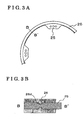
- Fig. 3A is a part plan view schematically illustrating a disc and a frictional member at a limiter portion of the torque fluctuation absorbing device according to the first embodiment of the present invention
- Fig. 3B is a part sectional view illustrating the disc and the frictional member at the limiter portion in Fig. 3A on a large scale;
- Fig. 4A is a part plan view schematically illustrating the disc and the frictional member at the limiter portion of the torque fluctuation absorbing device according to a second embodiment of the present invention
- Fig. 4B is a part sectional view illustrating the disc and the frictional member at the limiter portion in Fig. 4A on a large scale;
- Fig. 5A is another part plan view schematically illustrating the disc and the frictional member at the limiter portion of the torque fluctuation absorbing device according to the second embodiment of the present invention
- Fig. 5B is another part sectional view illustrating the disc and the frictional member at the limiter portion in Fig. 5A on a large scale;
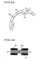
- Fig. 6A is a part plan view schematically illustrating the disc and the frictional member at the limiter portion of the torque fluctuation absorbing device according to a third embodiment of the present invention.
- Fig. 6B is a part sectional view illustrating the disc and the frictional member at the limiter portion in Fig. 6A on a large scale;
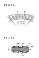
- Fig. 7A is a part plan view schematically illustrating the disc and the frictional member at the limiter portion of the torque fluctuation absorbing device according to a fourth embodiment of the present invention.
- Fig. 7B is a part sectional view illustrating the disc and the frictional member at the limiter portion in Fig. 7B on a large scale;
- Fig. 8 is a diagram for explaining a durability test result of the torque fluctuation absorbing device according to the first embodiment of the present invention.
- Fig. 9 is a diagram for explaining an age-based change of a limit torque value (corresponding to B/D (%) in Fig. 2) of the frictional member with respect to each actual length;
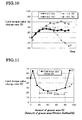
- Fig. 10 is a diagram for explaining a durability test result of a torque fluctuation absorbing device according to the second embodiment of the present invention.
- Fig. 11 is a diagram for explaining an age-based change of a limit torque value of the frictional member with respect to each area of the groove.
- a torque fluctuation-absorbing device 1 includes a support plate 10, a damping mechanism 20 and a limiter portion 30.
- the support plate 10 is a first rotational member configured to transmit a driving torque from a driving power source such as an engine to the damping mechanism 20.
- the damping mechanism 20 is adjusted to absorb fluctuation of a driving torque at the support plate 10 connected to a crankshaft of the engine.
- the limiter portion 30 limits the torque to be transmitted from the support plate 10 to a transmission input shaft.
- the damping mechanism 20 includes a hub 21, a side plate 22, a thrust member 23, a damper 24, a disc 25, a pair of frictional members 26 and a rivet.
- the hub 21 is integrally provided with a flange portion 21a extending radially outwardly.
- the hub 21 is further provided with a spline portion 21b at an inner surface of a central bore thereof, which is spline engaged with the transmission input shaft.
- a pair of spring seats 24a is disposed in each notched portion 21c, and an outer peripheral surface of the spring seat 24a is positioned to be outside of a radially outer side of an outer peripheral surface of the flange portion 21a.
- the side plate 22 includes a first side plate 22A and a second side plate 22B. As illustrated in Fig. 2, the first and second side plates 22A and 22B are oriented along both axial surfaces of the flange portion 21a to be substantially coaxial with the hub 21, respectively. The first and second side plates 22A and 22B rotate relative to the hub 21. Each of the first and second side plates 22A and 22B has a penetrating hole at a radially outer portion thereof so as to be riveted with the disc 25 together. Each of the first and second side plates 22A and 22B has at least one window bore 22c for housing the damper 24 therein. According to the first embodiment of the present invention, there are four window bores 22c for housing the dampers 24 therein, respectively.
- the thrust member 23 is an approximately ring-shaped member disposed between an inner surface of the side plate 22 and an outer surface of the hub 21.
- the inner surface of the side plate 22 becomes in contact with the outer surface of the hub 21.
- the thrust member 23 includes a first thrust member 23A, which is disposed between the outer surface of the hub 21 and the inner surface of the first side plate 22A, a second thrust member 23B, which is disposed between the outer surface of the hub 21 and the inner surface of the second side plate 22B, and a disc spring 23c (i.e., biasing means). Therefore, a hysteresis torque is generated between the flange portion 21a of the hub 21 and the side plate 22.
- the disc spring 23c is not limited to a disc spring.
- the damper 24 includes a coil spring and is housed in the notched portion 21c of the hub 21 and the window bore 22c of the side plate 22.
- the notched portions 21c substantially face the window bores 22c, respectively.
- the disc 25 is an approximately annular-shaped disc and extends in a more radially outward direction than an outer circumference of the side plate 22. A vicinity of an inner circumference of the disc 25 has been held by the side plate 22 and includes a penetrating hole for connecting the disc 25 with the side plate 22.
- the pair of frictional members 26 of approximately annular-shaped is fixed at both axial surfaces of the disc 25, as illustrated in Fig. 2. According to the first embodiment of the present invention, the pair of frictional members 26 is adhered at the both surfaces of the disc 25 with an adhesive. A frictional surface of the one frictional member 26 (illustrated at a right side in Fig.
- an actual length of at least one of the frictional members 26 in a radial direction thereof ranges substantially between 1% and 6% inclusive, of a major diameter of the frictional member 26.
- the actual length of the frictional member 26 is indicated with an alphabetic mark B in Fig. 2. Therefore, the rate of the actual length of the frictional member 26 relative to the major diameter of the frictional member 26 can be denoted with B/D (%). It is preferable that the rate ranges substantially between 2% and 6%, inclusive. It is further preferable that the rate ranges substantially between 3% and 6%, inclusive.
- At least one of the frictional members 26 (both of them according to the first embodiment) has at least one projected portion 26d in order to improve a fixing performance between the frictional member 26 and the disc 25, as illustrated in Fig. 3B.
- the disc 25 has a recessed portion such as a concave portion, a bore and so on, in which the projected portion 26d fits.
- This structure of the frictional member 26 and the disc 25 can be applied to second, third and fourth embodiments (described later).
- the frictional member 26 can have a groove (not shown) for emitting frictional powder generated in response to the frictional engagement.
- the frictional powder of the frictional member 26 can be emitted into an outer ambient environment by use of a centrifugal force.
- the groove can be a slit communicating between a radially inner side of the frictional member 26 and a radially outer side thereof. Still further, it is preferable that the frictional member 26 is made of a material having an elastic force so as to substantially uniformly and frictionally engage the frictional surface of each frictional member 26 with the frictional surface plate.
- the rivet 27 connects the disc 25 with the side plate 22.
- the limiter portion 30 includes the first frictional surface plate 31, the second frictional surface plate 32, a disc spring 33 and a rivet 34.
- the limiter portion 30 can be interpreted to also include the frictional members 26.
- the first frictional surface plate 31 is fixed at the support plate 10 via the rivet 34.
- the first frictional surface plate 31 is frictionally engaged with the one frictional member 26 (illustrated at the right side in Fig. 2) from a side opposite to the support plate 10.
- the first frictional surface plate 31 can have a hole or groove (not shown) in order to emit a frictional powder of the frictional members 26 into an outer ambient environment.
- the second frictional surface plate 32 is frictionally engaged with the other frictional member 26 (illustrated at the left side in Fig.
- the disc spring 33 is oriented between the support plate 10 and the second frictional surface plate 32 and biases the second frictional surface plate 32 in a right direction in Fig. 2, i.e., in a direction for keeping the second frictional surface plate 32 away from the support plate 10. Therefore, The frictional members 26 can be held by the first frictional surface plate 31 and the second frictional surface plate 32 such that the support plate 10 and the damping mechanism 20 can be maintained at a frictionally engaged condition.
- the rivet 34 fixes the support plate 10 and the first frictional surface plate 31.
- the frictional members 26 are held by the first frictional surface plate 31 and the second frictional surface plate 32.
- a frictional member can be disposed between a portion of the support plate 10 and the second frictional surface plate 32. In this case, when the fluctuating torque reaches the predetermined value (i.e., limit torque value), the frictional member slips relative to the support plate 10.
- the support plate 10 rotates in response to the driving force from the engine. While the fluctuating torque is smaller than the limit torque value, a rotational torque is transmitted to the disc 25 of the damping mechanism 20 and the side plate 22 via the limiter portion 30, wherein the damping mechanism 20 rotates.
- the rotational torque of the side plate 22 is transmitted to the hub 21 via the damper 24, the thrust member 23 and the flange portion 21a, wherein the hub 21 starts rotating.
- the damper 24 is elastically compressed in response to the amount of the fluctuating torque.
- the driving force of the diving power source is transmitted to the transmission input shaft via the damping mechanism 20.
- the torque fluctuation is inputted into the torque fluctuation absorbing device 1 at the predetermined number of times by repeatedly starting and stopping the engine activation.
- the y-axis of the diagram in Fig. 8 indicates a rate of an increase of the limit torque value under a condition that an initial limit torque value at the first use of this device is substantially zero percent.
- the x-axis thereof indicates a time transit for transmitting the torque fluctuation to this device 1 at the predetermined number of times.
- the predetermined number of times for transmitting the torque fluctuation to this device 1 can be determined based upon the number of torque fluctuations detected while a vehicle actually has run about 100, 000 kilometers.
- FIG. 8 show the age-based changes of the limit torque values of the frictional member 26, of which actual lengths (corresponding to B/D (%) in Fig. 2) are set at 1 percent and 6 percents of the major diameter of the frictional member 26, respectively. According to the results explained by these two solid lines in Fig. 8, each limit torque value becomes steady at an approximately 30- percent increase relative to the limit torque value at the substantially zero percent. This test results shows that the age-based change (i.e., increasing rate) of the limit torque value of the frictional member 26 can be effectively restrained.
- Fig. 9 is a diagram for explaining an age-based change of the limit torque value (corresponding to B/D (%) in Fig. 2) of the frictional member 26 with respect each actual length.
- Fig. 9 shows a stabled increasing rate of the frictional member 26 having each actual length indicated by the x-axis in the diagram. As illustrated in Fig. 8, the stabled increasing rate is detected by inputting the torque fluctuation at the predetermined number of times.
- the limit torque value is increased at a rate of less than 30 percents relative to the initial limit torque value when the actual length of the frictional member 26 ranged between 1 percent and 6 percents, inclusive. However, once the actual length of the frictional member 26 exceeds 10 percents of the major diameter of the frictional member 26, the limit torque value is increased more than 50 percents of the initial limit torque value.
- the radial actual length of the frictional member 26 ranges substantially between 1 percent and 6 percents of the major diameter of the frictional member 26, in order to improve a contact performance of the frictional members 26.
- the torque fluctuation absorbing device 1 according to the second embodiment of the present invention there is a difference in a structure of the frictional members 26 fixed at the disc 25 from the one according to the first embodiment of the present invention.
- the other components of the torque fluctuation absorbing device 1 according to the second embodiment of the present invention possess the same construction as the ones according to the first embodiment and so a detailed description thereof will be omitted hereinbelow.
- At least one of the frictional members 26 has a non-frictional portion (i.e., groove 26a) ranging substantially between 20 percents and 80 percents of an entire frictional surface area of the at least one of the frictional members 26. It is preferable that the frictional member 26 is designed to have the non-frictional portion ranges substantially between 30 percents and 70 percents of the entire frictional surface area of the frictional member 26. It is more preferable that the non-frictional portion ranges substantially between 40 percents and 60 percents thereof.
- the non-frictional portion can be a recessed portion such as a concave portion, a groove and so on as non-limiting examples.
- the non-frictional portion such as the groove 26a communicates between the inner peripheral side of the frictional member 26 and the outer peripheral thereof so as to emit the frictional powder of the frictional members 26 into the outer ambient environment by use of the centrifugal force.
- the pair of frictional members 26 is adhered at the both surfaces of the disc 25 with the adhesive.
- the disc 25 can preferably have an axially penetrating hole.
- the pair of frictional members 26 is provided with a bridging portion 26e for integrally connecting the frictional members 26 through the penetrating hole.
- the fictional members 26 are made of a material having an elastic force so as to substantially uniformly and frictionally engage the frictional surface of each frictional members 26 with the frictional surface plate.
- the torque fluctuation is inputted into the torque fluctuation absorbing device 1 at the predetermined number of times by repeatedly starting and stopping the engine activation.
- the y-axis of the diagram in Fig. 10 indicates a rate of an increase of the limit torque value under a condition that an initial limit torque value at the first use of this device is substantially zero percent.
- the x-axis thereof indicates a time transit for transmitting the torque fluctuation to this device 1 at the predetermined number of times.
- the predetermined number of times for transmitting the torque fluctuation to this device 1 can be determined based upon the number of torque fluctuations detected while a vehicle actually has run about 100, 000 kilometers.
- FIG. 10 show the age-based changes of the limit torque values of the frictional member 26 of which groove 26a is set at 20 percents and 80 percents of the entire frictional surface area of the frictional member 26, respectively. According to the results explained by these two solid lines in Fig. 10, each limit torque value becomes steady at an approximately 30-percent increase relative to the limit torque value at the substantially zero percent. This test results show that the age-based change (i.e., increasing rate) of the limit torque value of the frictional member 26 can be effectively restrained.
- Fig. 11 is a diagram for explaining an age-based change of the limit torque value of the frictional member 26 with respect each rate of the groove area.
- Fig. 11 shows a stabled increasing rate of the frictional member 26 having each actual groove area rate (amount) indicated by the x-axis in the diagram. As illustrated in Fig. 10, the stabled increasing rate is detected by inputting the torque fluctuation at the predetermined number of times.
- the change rate of the limit torque value is effectively restrained at an approximately 30 percents.
- the torque fluctuation absorbing device 1 according to the third embodiment of the present invention there is a difference in a structure of the frictional member 26 fixed at the disc 25 from the one according to the first embodiment of the present invention.
- the other components of the torque fluctuation absorbing device 1 according to the third embodiment of the present invention possess the same construction as the ones according to the first embodiment of and so a detailed description thereof will be omitted hereinbelow.
- at least one of the frictional members 26 is configured with plural block-shaped frictional materials.
- the frictional member 26 is allocated at the disc 25 so as to set a frictional surface of the frictional member 26 substantially between 20 percents and 80 percents of an entire surface area of the disc 25, at which the frictional member 26 can be allocated.
- the area of the plural block-shaped materials ranges substantially between 30 percents and 70 percents of the entire surface area of the disc 25. It is more preferable that the area of the plural block-shaped materials ranges substantially between 40 percents and 60 percents of the entire surface area thereof.
- an area, at which the frictional member 26 can be allocated at the disc 25, substantially corresponds to an area excluding an area, which can come in contact with the side plate 22, when the disc 25 is riveted with the side plate 22.
- An area, at which the frictional member 26 has not been allocated in the area at which the frictional member 26 can be allocated, can preferably communicate between the inner peripheral side and the outer peripheral side in order to emit the frictional powder of the frictional members 26 into the external ambient environment by use of the centrifugal force.
- a non-frictional portion is defined at the frictional surface thereof.
- the non-frictional portion can be substantially the same as the groove 26a in Fig. 4.
- the non-frictional, portion can be a recessed portion such as a groove, a concave portion and so on as non-limiting examples.
- the non-frictional portion such as the groove communicates between the inner peripheral side and the outer peripheral side of the frictional member 26 so as to emit the frictional powder of the frictional members 26 into the outer ambient environment by use of the centrifugal force.
- the pair of frictional members 26 is adhered at the both surfaces of the disc 25 with the adhesive.
- at least one of the frictional members 26 has at least one projected portion in the same manner as the projected portion 26d illustrated in Fig. 3.
- the disc 25 has a recessed portion such as a concave portion or a bore, in which the projected portion fits.
- the pair of frictional members 26 is provided with a bridging portion (similar to the bridging portion 26e in Fig. 4) for integrally connecting the frictional members 26 through a penetrating hole at the disc 25. It is still further preferable that the frictional member 26 is made of a material having an elastic force so as to substantially equalize a contact performance of the frictional surface of each frictional member 26.
- the torque fluctuation absorbing device 1 according to the fourth embodiment of the present invention is provided with a reinforcing member 26b.
- the reinforcing member 26b can be integral with at least one of the frictional members 26 according to the first, second and third embodiments of the present invention.
- the reinforcing member 26b possesses a stronger property than the frictional members 26.
- the other components of the torque fluctuation absorbing device 1 according to the fourth embodiment of the present invention possesses the same construction as the ones according to the first, second and third embodiments and so a detailed description thereof will be omitted hereinbelow.
- the reinforcing member 26b projects at both radial ends portions of the frictional surface less than at the vicinity of a central portion of the frictional surface.
- the reinforcing members 26b projects at both radial ends portions of the frictional surface less than at the vicinity of the central portion thereof.
- the reinforcing member 26b can be made of a heat-resisting fiber such as a glass fiber, a carbon fiber, a metal fiber, an asbestos, an alamido fiber and so on as non-limiting examples. Therefore, the frictional plates can be effectively prevented from being damaged by an edge of the reinforcing member 26b. A surface roughness of the corresponding frictional surface can be restrained from being changed such that the limit torque value can be stabilized.
- the torque fluctuation absorbing device 1 according to the fifth embodiment of the present invention is different from the devices according to the first, second, third and fourth embodiments, in which a frictional surface of at least one of the frictional surface plates 31 and 32 and the frictional surface of at least one of the frictional members 26 corresponding to the at least one of the frictional surface plates 31 and 32 are roughened, for example shot peening, bonderizing process and so on. Apart from the roughened frictional surface thereof, the device 1 according to the fifth embodiment of the present invention is substantially the same as the device 1 according to the first, second, third and fourth embodiments.
- the corresponding frictional surfaces of the at least one of the frictional surface plate and the frictional member can be roughened, thereby enabling to increase only an initial frictional coefficient. Therefore, if the only initial frictional coefficient, which has a characteristic of age-based increase, is increased, the change rate of the frictional coefficient is decreased such that the limit torque value can be effectively stabilized.
- a torque fluctuation absorbing device includes a first rotational member transmitted with a torque from a driving power source, a damping mechanism connected with an input shaft of a transmission, the damping mechanism having a pair of frictional members of approximately annular-shaped fixed at both surfaces of a disc, and a limiter portion for frictionally engaging the pair of frictional members with the first rotational member in a substantially direct manner or in a substantially indirect manner via a pair of frictional plates.
- An actual length of at least one of the pair of frictional members ranges substantially between 1 percent and 6 percents of a major diameter of the at least one of the pair of frictional members.
Landscapes
- Engineering & Computer Science (AREA)
- General Engineering & Computer Science (AREA)
- Physics & Mathematics (AREA)
- Acoustics & Sound (AREA)
- Aviation & Aerospace Engineering (AREA)
- Mechanical Engineering (AREA)
- Mechanical Operated Clutches (AREA)
- One-Way And Automatic Clutches, And Combinations Of Different Clutches (AREA)
Applications Claiming Priority (4)
| Application Number | Priority Date | Filing Date | Title |
|---|---|---|---|
| JP2003337132 | 2003-09-29 | ||
| JP2003337132 | 2003-09-29 | ||
| JP2004264368A JP4581576B2 (ja) | 2003-09-29 | 2004-09-10 | トルク変動吸収装置 |
| JP2004264368 | 2004-09-10 |
Publications (2)
| Publication Number | Publication Date |
|---|---|
| EP1519075A1 true EP1519075A1 (de) | 2005-03-30 |
| EP1519075B1 EP1519075B1 (de) | 2010-05-05 |
Family
ID=34197271
Family Applications (1)
| Application Number | Title | Priority Date | Filing Date |
|---|---|---|---|
| EP04023063A Expired - Lifetime EP1519075B1 (de) | 2003-09-29 | 2004-09-28 | Vorrichtung zur Dämpfung von Drehmomentschwankungen |
Country Status (4)
| Country | Link |
|---|---|
| US (2) | US7207887B2 (de) |
| EP (1) | EP1519075B1 (de) |
| JP (1) | JP4581576B2 (de) |
| DE (1) | DE602004026973D1 (de) |
Cited By (3)
| Publication number | Priority date | Publication date | Assignee | Title |
|---|---|---|---|---|
| EP2226528A3 (de) * | 2009-03-05 | 2016-11-23 | Aisin Seiki Kabushiki Kaisha | Drehmomentschwankungsaufnehmer |
| FR3060072A1 (fr) * | 2016-12-12 | 2018-06-15 | Peugeot Citroen Automobiles Sa | Element mecanique circulaire de transmission de mouvement |
| FR3130341A1 (fr) * | 2021-12-13 | 2023-06-16 | Valeo Embrayages | Dispositif d’amortissement de torsion |
Families Citing this family (21)
| Publication number | Priority date | Publication date | Assignee | Title |
|---|---|---|---|---|
| JP4725348B2 (ja) | 2006-02-16 | 2011-07-13 | アイシン精機株式会社 | トルク変動吸収装置 |
| JP4894467B2 (ja) * | 2006-11-08 | 2012-03-14 | アイシン精機株式会社 | トルク変動吸収装置 |
| JP5123708B2 (ja) * | 2008-03-29 | 2013-01-23 | アイシン・エィ・ダブリュ工業株式会社 | リミッタ付きダンパ |
| JP5098825B2 (ja) * | 2008-06-03 | 2012-12-12 | アイシン精機株式会社 | トルク変動吸収装置 |
| JP5481897B2 (ja) | 2009-03-25 | 2014-04-23 | アイシン精機株式会社 | トルク変動吸収装置 |
| JP5272853B2 (ja) | 2009-03-31 | 2013-08-28 | アイシン精機株式会社 | トルク変動吸収装置 |
| JP5691367B2 (ja) | 2009-10-27 | 2015-04-01 | アイシン精機株式会社 | トルク変動吸収装置 |
| US9127720B2 (en) | 2009-12-11 | 2015-09-08 | Mitsubishi Electric Corporation | Torque fluctuation absorbing apparatus |
| JP5499998B2 (ja) * | 2010-08-31 | 2014-05-21 | 日産自動車株式会社 | 駆動力伝達装置 |
| JP5742326B2 (ja) | 2011-03-15 | 2015-07-01 | アイシン精機株式会社 | トルク変動吸収装置 |
| JP5671382B2 (ja) * | 2011-03-15 | 2015-02-18 | アイシン精機株式会社 | 伝達トルク制限装置 |
| JP5223999B2 (ja) * | 2011-04-01 | 2013-06-26 | トヨタ自動車株式会社 | 捩り振動減衰装置 |
| JP5724629B2 (ja) * | 2011-05-25 | 2015-05-27 | アイシン精機株式会社 | トルク変動吸収装置 |
| WO2012168997A1 (ja) | 2011-06-06 | 2012-12-13 | トヨタ自動車株式会社 | 車両用トルクリミッタ装置 |
| JP5131369B2 (ja) * | 2011-08-03 | 2013-01-30 | アイシン精機株式会社 | トルク変動吸収装置 |
| DE102018130237A1 (de) * | 2018-11-29 | 2020-06-04 | Schaeffler Technologies AG & Co. KG | Drehschwingungsdämpfer |
| JP2020148335A (ja) * | 2019-03-15 | 2020-09-17 | 株式会社エクセディ | トルクリミッタ装置 |
| JP7633115B2 (ja) | 2021-08-02 | 2025-02-19 | 株式会社エクセディ | トルクリミッタ |
| US11924678B2 (en) | 2021-11-17 | 2024-03-05 | Charter Communications Operating, Llc | Adapting TCP in SAS-controlled CBRS networks |
| JP2024051353A (ja) * | 2022-09-30 | 2024-04-11 | 株式会社アイシン | ダンパ装置 |
| WO2025134629A1 (ja) * | 2023-12-18 | 2025-06-26 | アイシン化工株式会社 | 乾式摩擦材、トルクリミッター装置及び乾式摩擦材の製造方法 |
Citations (5)
| Publication number | Priority date | Publication date | Assignee | Title |
|---|---|---|---|---|
| US5526714A (en) * | 1992-08-20 | 1996-06-18 | Fichtel & Sachs Ag | Torsional vibration damper for the drive line of a motor vehicle |
| US5771999A (en) * | 1995-08-01 | 1998-06-30 | Fichtel & Sachs Ag | Clutch disc with a compound friction disc |
| US20020092715A1 (en) * | 2000-12-14 | 2002-07-18 | Nsk-Warner K.K. | Damper assembly with torque limiter |
| US20030087704A1 (en) * | 2001-10-17 | 2003-05-08 | Makoto Takeuchi | Torque fluctuation absorber |
| EP1462675A2 (de) * | 2003-03-27 | 2004-09-29 | LuK Lamellen und Kupplungsbau Beteiligungs KG | Drehschwingungsdämpfer |
Family Cites Families (24)
| Publication number | Priority date | Publication date | Assignee | Title |
|---|---|---|---|---|
| US1746110A (en) * | 1929-02-21 | 1930-02-04 | Asbestos Mfg Company | Brake lining |
| US3323328A (en) * | 1964-11-13 | 1967-06-06 | Borg Warner | Torque limiting clutch |
| US3841949A (en) * | 1972-10-25 | 1974-10-15 | Twin Disc Inc | Composite friction plate |
| JPS601497B2 (ja) * | 1978-08-03 | 1985-01-16 | アイシン精機株式会社 | 回転トルク伝達装置 |
| JPS5614628A (en) * | 1979-07-16 | 1981-02-12 | Shinko Electric Co Ltd | Electromagnetic friction clutch or brake |
| JPS582425U (ja) * | 1981-06-30 | 1983-01-08 | 株式会社大金製作所 | クラツチデイスクのフエ−シング取付構造 |
| JPS60114335U (ja) * | 1984-01-11 | 1985-08-02 | 三菱自動車工業株式会社 | クラツチデイスク |
| GB2240142B (en) * | 1990-01-10 | 1994-02-23 | Automotive Products Plc | A friction facings and carrier assembly |
| JPH0495622A (ja) * | 1990-08-10 | 1992-03-27 | Aisin Chem Co Ltd | クラッチフェーシング |
| JPH0446252U (de) * | 1990-08-24 | 1992-04-20 | ||
| JPH04119227A (ja) * | 1990-09-06 | 1992-04-20 | Toyota Motor Corp | クラッチ相手体 |
| JPH07190112A (ja) * | 1993-12-28 | 1995-07-28 | Mitsubishi Materials Corp | フェーシング材 |
| JP3831430B2 (ja) * | 1995-05-23 | 2006-10-11 | Nskワーナー株式会社 | 湿式摩擦材の製造方法 |
| JPH09126257A (ja) * | 1995-10-27 | 1997-05-13 | Shinko Electric Co Ltd | 摩擦式継手の摩擦板 |
| JPH09257068A (ja) * | 1996-03-21 | 1997-09-30 | Nok Corp | 摩擦板 |
| US6524681B1 (en) * | 1997-04-08 | 2003-02-25 | 3M Innovative Properties Company | Patterned surface friction materials, clutch plate members and methods of making and using same |
| JPH11193842A (ja) * | 1997-11-07 | 1999-07-21 | Aisin Seiki Co Ltd | 摩擦材 |
| JP2000063803A (ja) * | 1998-08-19 | 2000-02-29 | Nsk Warner Kk | 湿式摩擦材 |
| DE10015206A1 (de) * | 1999-04-01 | 2000-10-05 | Luk Lamellen & Kupplungsbau | Kupplungsscheibe |
| JP3683165B2 (ja) * | 2000-07-27 | 2005-08-17 | トヨタ自動車株式会社 | トルク変動吸収装置のトルクリミッター部組付け偏芯低減構造および方法 |
| JP4277507B2 (ja) * | 2001-10-17 | 2009-06-10 | アイシン精機株式会社 | トルク変動吸収装置 |
| JP2003278836A (ja) * | 2002-03-26 | 2003-10-02 | Aisin Seiki Co Ltd | トルク変動吸収装置 |
| JP2004019834A (ja) * | 2002-06-18 | 2004-01-22 | Aisin Seiki Co Ltd | トルク変動吸収装置 |
| JP2005299840A (ja) * | 2004-04-14 | 2005-10-27 | Nippon Valqua Ind Ltd | 被膜付き摩擦材およびその製造方法 |
-
2004
- 2004-09-10 JP JP2004264368A patent/JP4581576B2/ja not_active Expired - Fee Related
- 2004-09-28 EP EP04023063A patent/EP1519075B1/de not_active Expired - Lifetime
- 2004-09-28 DE DE602004026973T patent/DE602004026973D1/de not_active Expired - Lifetime
- 2004-09-28 US US10/950,657 patent/US7207887B2/en not_active Expired - Lifetime
-
2007
- 2007-03-12 US US11/716,577 patent/US7425181B2/en not_active Expired - Lifetime
Patent Citations (6)
| Publication number | Priority date | Publication date | Assignee | Title |
|---|---|---|---|---|
| US5526714A (en) * | 1992-08-20 | 1996-06-18 | Fichtel & Sachs Ag | Torsional vibration damper for the drive line of a motor vehicle |
| US5771999A (en) * | 1995-08-01 | 1998-06-30 | Fichtel & Sachs Ag | Clutch disc with a compound friction disc |
| US20020092715A1 (en) * | 2000-12-14 | 2002-07-18 | Nsk-Warner K.K. | Damper assembly with torque limiter |
| US20030087704A1 (en) * | 2001-10-17 | 2003-05-08 | Makoto Takeuchi | Torque fluctuation absorber |
| JP2003194095A (ja) * | 2001-10-17 | 2003-07-09 | Aisin Seiki Co Ltd | トルク変動吸収装置 |
| EP1462675A2 (de) * | 2003-03-27 | 2004-09-29 | LuK Lamellen und Kupplungsbau Beteiligungs KG | Drehschwingungsdämpfer |
Non-Patent Citations (1)
| Title |
|---|
| PATENT ABSTRACTS OF JAPAN vol. 2003, no. 11 5 November 2003 (2003-11-05) * |
Cited By (7)
| Publication number | Priority date | Publication date | Assignee | Title |
|---|---|---|---|---|
| EP2226528A3 (de) * | 2009-03-05 | 2016-11-23 | Aisin Seiki Kabushiki Kaisha | Drehmomentschwankungsaufnehmer |
| FR3060072A1 (fr) * | 2016-12-12 | 2018-06-15 | Peugeot Citroen Automobiles Sa | Element mecanique circulaire de transmission de mouvement |
| WO2018109291A1 (fr) * | 2016-12-12 | 2018-06-21 | Psa Automobiles Sa | Pignon de transmission de mouvement |
| CN110073121A (zh) * | 2016-12-12 | 2019-07-30 | 标致雪铁龙汽车股份有限公司 | 用于传递运动的小齿轮 |
| CN110073121B (zh) * | 2016-12-12 | 2021-04-02 | 标致雪铁龙汽车股份有限公司 | 用于传递运动的小齿轮 |
| FR3130341A1 (fr) * | 2021-12-13 | 2023-06-16 | Valeo Embrayages | Dispositif d’amortissement de torsion |
| WO2023110931A1 (fr) * | 2021-12-13 | 2023-06-22 | Valeo Embrayages | Dispositif d'amortissement de torsion |
Also Published As
| Publication number | Publication date |
|---|---|
| US7207887B2 (en) | 2007-04-24 |
| JP2005127507A (ja) | 2005-05-19 |
| EP1519075B1 (de) | 2010-05-05 |
| US20050067249A1 (en) | 2005-03-31 |
| JP4581576B2 (ja) | 2010-11-17 |
| US20070155513A1 (en) | 2007-07-05 |
| US7425181B2 (en) | 2008-09-16 |
| DE602004026973D1 (de) | 2010-06-17 |
Similar Documents
| Publication | Publication Date | Title |
|---|---|---|
| US7425181B2 (en) | Torque fluctuation absorbing device | |
| EP1528283B1 (de) | Vorrichtung zur Dämpfung von Drehmomentschwankungen | |
| US6083130A (en) | Serpentine drive system with improved over-running alternator decoupler | |
| US7559844B2 (en) | Torque fluctuation absorber | |
| US4185728A (en) | Clutch disc with variable deflection rate vibration damper | |
| JP4978321B2 (ja) | トルク変動吸収装置 | |
| EP2233780A2 (de) | Drehmomentschwankungsaufnehmer | |
| US20100116617A1 (en) | Isolator with one-way clutch | |
| US8696474B2 (en) | Torque fluctuation absorber | |
| CN102203450A (zh) | 具有转矩限制器的超越解耦器 | |
| US20020153221A1 (en) | Friction clutch | |
| JPH0666349A (ja) | トルクを伝達するための装置 | |
| CN115176096B (zh) | 用于传动系的具有旋转轴线的扭振阻尼器 | |
| CN112797088B (zh) | 离合器盘及扭矩限制器 | |
| CN108223689B (zh) | 扭矩变动吸收装置 | |
| US5857552A (en) | Plate member having radially extending support portions for a damper disc assembly | |
| US6056103A (en) | Dampening disk assembly | |
| US4586596A (en) | Clutch plate with a composite torsion damping hub | |
| US6223625B1 (en) | Torque transmitting and torsion damping apparatus for use in motor vehicles | |
| JP5131369B2 (ja) | トルク変動吸収装置 | |
| JP5012927B2 (ja) | トルク変動吸収装置 | |
| KR101549330B1 (ko) | 토크 전달 장치의 댐퍼 기구 | |
| JP2000320614A (ja) | 動力伝達装置 | |
| US5782694A (en) | Damper disc assembly having a plate formed with lubricating members for reducing friction caused by engagement with damper springs | |
| US6978695B2 (en) | Flywheel assembly |
Legal Events
| Date | Code | Title | Description |
|---|---|---|---|
| PUAI | Public reference made under article 153(3) epc to a published international application that has entered the european phase |
Free format text: ORIGINAL CODE: 0009012 |
|
| AK | Designated contracting states |
Kind code of ref document: A1 Designated state(s): AT BE BG CH CY CZ DE DK EE ES FI FR GB GR HU IE IT LI LU MC NL PL PT RO SE SI SK TR |
|
| AX | Request for extension of the european patent |
Extension state: AL HR LT LV MK |
|
| 17P | Request for examination filed |
Effective date: 20050908 |
|
| AKX | Designation fees paid |
Designated state(s): DE FR GB |
|
| GRAP | Despatch of communication of intention to grant a patent |
Free format text: ORIGINAL CODE: EPIDOSNIGR1 |
|
| GRAS | Grant fee paid |
Free format text: ORIGINAL CODE: EPIDOSNIGR3 |
|
| GRAA | (expected) grant |
Free format text: ORIGINAL CODE: 0009210 |
|
| AK | Designated contracting states |
Kind code of ref document: B1 Designated state(s): DE FR GB |
|
| REG | Reference to a national code |
Ref country code: GB Ref legal event code: FG4D |
|
| REF | Corresponds to: |
Ref document number: 602004026973 Country of ref document: DE Date of ref document: 20100617 Kind code of ref document: P |
|
| PLBE | No opposition filed within time limit |
Free format text: ORIGINAL CODE: 0009261 |
|
| STAA | Information on the status of an ep patent application or granted ep patent |
Free format text: STATUS: NO OPPOSITION FILED WITHIN TIME LIMIT |
|
| 26N | No opposition filed |
Effective date: 20110208 |
|
| GBPC | Gb: european patent ceased through non-payment of renewal fee |
Effective date: 20100928 |
|
| REG | Reference to a national code |
Ref country code: DE Ref legal event code: R097 Ref document number: 602004026973 Country of ref document: DE Effective date: 20110207 |
|
| PG25 | Lapsed in a contracting state [announced via postgrant information from national office to epo] |
Ref country code: GB Free format text: LAPSE BECAUSE OF NON-PAYMENT OF DUE FEES Effective date: 20100928 |
|
| REG | Reference to a national code |
Ref country code: DE Ref legal event code: R084 Ref document number: 602004026973 Country of ref document: DE Effective date: 20140527 |
|
| REG | Reference to a national code |
Ref country code: FR Ref legal event code: PLFP Year of fee payment: 13 |
|
| REG | Reference to a national code |
Ref country code: FR Ref legal event code: PLFP Year of fee payment: 14 |
|
| REG | Reference to a national code |
Ref country code: FR Ref legal event code: PLFP Year of fee payment: 15 |
|
| PGFP | Annual fee paid to national office [announced via postgrant information from national office to epo] |
Ref country code: DE Payment date: 20190917 Year of fee payment: 16 |
|
| REG | Reference to a national code |
Ref country code: DE Ref legal event code: R119 Ref document number: 602004026973 Country of ref document: DE |
|
| PG25 | Lapsed in a contracting state [announced via postgrant information from national office to epo] |
Ref country code: DE Free format text: LAPSE BECAUSE OF NON-PAYMENT OF DUE FEES Effective date: 20210401 |
|
| PGFP | Annual fee paid to national office [announced via postgrant information from national office to epo] |
Ref country code: FR Payment date: 20210812 Year of fee payment: 18 |
|
| PG25 | Lapsed in a contracting state [announced via postgrant information from national office to epo] |
Ref country code: FR Free format text: LAPSE BECAUSE OF NON-PAYMENT OF DUE FEES Effective date: 20220930 |