EP1517824B1 - Etancon - Google Patents
Etancon Download PDFInfo
- Publication number
- EP1517824B1 EP1517824B1 EP03761420A EP03761420A EP1517824B1 EP 1517824 B1 EP1517824 B1 EP 1517824B1 EP 03761420 A EP03761420 A EP 03761420A EP 03761420 A EP03761420 A EP 03761420A EP 1517824 B1 EP1517824 B1 EP 1517824B1
- Authority
- EP
- European Patent Office
- Prior art keywords
- stanchion
- lever
- fixing member
- runge
- supporting element
- Prior art date
- Legal status (The legal status is an assumption and is not a legal conclusion. Google has not performed a legal analysis and makes no representation as to the accuracy of the status listed.)
- Expired - Lifetime
Links
Images


Classifications
-
- B—PERFORMING OPERATIONS; TRANSPORTING
- B62—LAND VEHICLES FOR TRAVELLING OTHERWISE THAN ON RAILS
- B62D—MOTOR VEHICLES; TRAILERS
- B62D33/00—Superstructures for load-carrying vehicles
- B62D33/02—Platforms; Open load compartments
- B62D33/0222—Connecting elements between stanchions, e.g. roof supporting elements, stiffeners
-
- B—PERFORMING OPERATIONS; TRANSPORTING
- B62—LAND VEHICLES FOR TRAVELLING OTHERWISE THAN ON RAILS
- B62D—MOTOR VEHICLES; TRAILERS
- B62D33/00—Superstructures for load-carrying vehicles
- B62D33/02—Platforms; Open load compartments
- B62D33/0207—Connections of movable or detachable racks or stanchions to platforms
Definitions
- the invention relates to a stanchion according to the preamble of claim 1.
- Tarpaulins such as sliding covers provided.
- Such a Tarpaulin construction can be used for constructions of truck beds or of Semitrailers be designed, but also in containers or Railcars.
- sliding covers are to load these quickly or to be able to unload, the side tarpaulins hanging from the carriers fauxschiebbar, and also running between the side rails Roof tarpaulin can by means of movable bow, to which the roof tarpaulin is fixed, pushed together.
- the top frames of the sliding covers are lightweight dismountable designed.
- the Mittelrungen should be fast can be removed, but often also the corner stanchions, which also as a post be referred to, in this second case, the carrier degraded while they are solving only the middle stalls at unmoved sliding roof by the posts sufficiently supported.
- Other tarpaulins supported a chassis roof, for example with low weight from a riveted on the side rails plastic film is formed so that the displacement of only the side tarpaulin is provided.
- stanchion arrangements where respectively a stanchion on a corresponding attachment member, which also as Runge shoe is called, lockable by means of quick release closure are, with the Runge shoe usually on a supporting outer part of the Loading surface of the sliding roof, such as a metal frame, the Wooden slats supported, is fixed, for example by screwing or by welding.
- a first known from practice embodiment of a lockable Mittelrunge has a lever assembly with an intermediate lever and a Main lever, wherein the intermediate lever with a first joint on the Runge and a second joint is hinged to the main lever and the Main lever on the long lever arm an operating handle and on the short lever arm has a training as a caulking.
- To lock the Runge becomes the stemming member behind an upwardly projecting nose of the Runge shoe set and by pressing the main lever, the Runge pushed upwards from the stanchion shoe over the two levers until the Lever assembly is locked.
- a second known from practice embodiment of a lockable Mittelrunge has a stirrup-like first lever, which in a U-profile a stanchion bearing is used, and a second lever which on the Body of the stanchion is hinged and the over an intermediate lever with a in the body of the Runge axially displaceable locking wedge is coupled, wherein the Rungenlager has a pocket for receiving the locking wedge.
- the locking wedge is then by pressing the second lever in the bag lowered the stanchion bearing and thereby the unstable around the joint with the first lever tilting Runge locked.
- the locking wedge can only in case of failure the first lever and its dynamically stressed joint on the Runge initiate vertical loads of the stanchion into the catch pocket, but this only on the second lever and its linkage, which is not designed for this purpose is. Furthermore, the displaceable locking wedge itself is another wear-prone part dar.
- the known Rurgian Alba is however difficult to handle, as they are manually in the raised position must be relocated.
- a third known from practice embodiment of a lockable Middle stanchion has a lever articulated on the body of the stanchion, whose one lever arm has a handle and whose other lever arm in a U-shaped stanchions bearing is insertable, wherein the Runge by pressing the Levers with the handle on the body of the stanchion is raised.
- the vertical forces are transferred from the stanchion via the lever into the stanchion Runge initiated.
- the stanchion is in its lower Range over a joint with a designed as a double-armed lever Pivoting member connected, at one end of a round rod trained end portion in a U-shaped bearing half-shell of a Attachment member is used.
- the pivot member directs the Weight forces over the joint into the stanchion.
- For mounting and unmounting the stanchion is at the other end of the round bar turned away Swivel member by means of an axis one end of an upper toggle link a knee lever connected, the other end of the upper Toggle link on another axis with a central region of a lower toggle link is connected.
- the lower toggle link is as formed double-armed lever whose lower lever arm over a Anlenkachse is connected in a slot with a locking wedge.
- Locking wedge is intended to be in a wedge pocket of the attachment member penetrate while the upper lever arm formed as an actuating lever is.
- the operating lever is by a snap device in kept closed state.
- the locking wedge is by a spring pressed into the key pocket.
- the Runge invention thus creates a reliable power flow of the attachment member to the body of Runge. Especially if that Counter bearing is fixed to the body of the stanchion are the transmit vertical forces reliably. The lifetime of such a stanchion is, because prone hinged parts are not after locking and in particular claimed while driving, significantly improved.
- the transfer of vertical forces from the attachment member to the Runge is particularly advantageous when the touch plane attachment member and support member and also the contact plane support member and Counter bearing horizontal and thus perpendicular to the main direction of the transmitted forces is formed or at least horizontal sections having.
- this preferred type of positive Arrangement a simple manufacture and an easy to calculate Design of the parts strengths.
- the boundaries of the support element, each adapted to the contour the two adjacent parts in several levels, e.g. in style with several gradations to facilitate insertion, or with one plane inclined to the horizontal, e.g. when the support element is a wedge shape having.
- the lower boundary of the support element in its Design adapted to known Runge shoes, so that at any time become obsolete stanchions from the prior art without modification of the Fastener be replaced by a Runge invention can or existing stanchions by retrofitting a support element and / or an abutment are carried out according to the invention.
- the support element of a Runge or attachment member detachable part which is stored separately when unlocking the stanchion and when locking the stanchion between the attachment member and the with the Runge firmly connected counter bearing is used.
- Support element preferably with its own handle for pulling out configured and may further comprise a collar portion with which it is in Insertion defined an end stop and if necessary a limit for a pivotally arranged on the stanchion lever.
- the detachable support element still have a hole for receiving a locking pin is provided, for example, the stanchion horizontal interspersed, in which case with unlocked Runge the removable support element with this locking pin could be held again.
- such a detachable would be such that it is also transversal fixing the stanchion to the attachment member; a possible embodiment can in a framing the attachment member and the foot area the stave framed form should be chosen.
- the support member on the attachment member or at one with the fastening member firmly connected part, such as the loading area, where the attachment member is fixed e.g. be arranged pivotally, so that when unlocking the stake the support element is not lost.
- the support element on a part the Runge, wherein the part or the support element conveniently is pivotally mounted on the stanchion, so that the support element also at unlocked stanchion is not lost.
- the stanchion according to the invention comprises a lever arrangement, such as a toggle lever assembly, preferably at least one lever on the stanchion stores, with which the stanchion can be raised, so that a raising of Hand is not required.
- a lever arrangement can both a directly to the body of the stanchion coupled lever as well as several levers include.
- an end of one of the levers for the Lift the stanchion be supportable against the fastening member and a corresponding, e.g. Having trained as a caulking end. Because the Joints and bearings of the lever in the invention Runge in her locked state no longer or significantly less stressed, The joints of the stanchion are no longer the critical component of the stanchion. It is preferably provided that the lever arrangement only for lifting or slowly lowering the engaged with the fastening member and hereafter can be posted.
- the is provided with a lever arrangement consists in arranging the Support member on one of the lever of the lever assembly. So will the advantageous Actuation of the lever assembly for locking with the insertion or to Unlocking combined with the removal of the support element without this additional handling will be required. As soon as that Support element is pulled out - which regularly only when standing Vehicle occurs, the lever assembly takes over the load of Runge until this is lowered. Conversely, the lever assembly with the lock relieved at the same time.
- the support element can in this case both from the outer Side as well as from the inner side of the stanchion.
- the stanchion has in its foot area below one for the Passing through the fastening member provided recess in her Body on a crossbar on, with locked Runge behind a down projecting nose of the attachment member is raised and thus a Fuse defined in the direction away from the cargo bed while the frame the loading area defined a stop for the foot of the stanchion.
- the in the locked state of the stanchion are raised so far that they are behind a extend laterally projecting part of the fastening member and thus the Complete securing with the crosspiece.
- the distance of the struts is Advantageously dimensioned so that they are the attachment member without or with frame little game and thus also a beating of the stakes in their Prevent transverse direction parallel to the crosspiece.
- the aspirations are there Advantageously dimensioned so that they slightly upwards with locked Runge protrude the laterally projecting part of the fastening member.
- the struts then also the support element laterally support, if this is so thick that it is between the in the Runge reaches in a rear area arranged struts.
- the recess in the foot region of the Runge of the Limiting abutment so that the support element small and thus with low Weight can be formed.
- the Runge invention can be advantageous by their training with a double-C profile that is uninterrupted over the length of the stanchion and preferably in the foot area in the region of the central recess Reinforcements has transferred very well vertical forces. Of the closed, not interrupted frame in the lower Runge part allows therefore a high burden of Runge. Furthermore, the stanchion defines at least in the central portion between the two C-shaped projections a charge-facing rear wall, in the simple way with Holes or the like. With little effort recordings for example a second horizontal floor for multi-storey loading with bad stackable goods or fasteners for cargo separations or Load securing or straps. The good transmission of the forces of Runge invention allows this without premature failure of the stanchion and without the need for separate support means are provided.
- An inventive stanchion arrangement or an inventive Tarpaulin structure are characterized by a Runge invention.
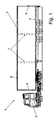
- the semitrailer 1 shown schematically in Fig. 1 consists of a Tractor 2 and a semi-trailer 3.
- the semi-trailer 3 is as Sliding roof formed in which a cargo area 4 in the corners arranged vertical post 5, the horizontal, in the direction of travel extending side member 6 and not visible in the side cross member support, wherein between the two posts 5 two stanchions 7 arranged are that connect the cargo area 4 with the side rails 6 and these vertically support.
- Sideboards hang from the side rails 6 side down, and a roof tarpaulin is displaceable between the two longitudinal members 6 arranged.
- To improve the load capacity of the loading platform is at Racks of sliding covers, as shown in Fig. 1, usually at least the stanchion 7 is designed so that it is out of its anchorage can be solved, sometimes the side members 6 and the post 5 solvable.
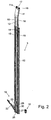
- FIG. 2 is the perspective view a preferred embodiment of a stanchion arrangement with a Runge 7 according to the invention and a fastening member 10, present as Runge shoe trained, the outside of the bed 4 of the Sliding roof 3 set, for example, is screwed, shown.
- the fastening member 10 consists of a U-shaped bent metal part 10a and a T-shaped metal part 10b, wherein in the vertically extending Section of the T-shaped metal part 10b and in the base of the U-shaped Metal part 10a aligned holes 10c are formed, can be passed through the fastening bolts to the Fix attachment member 10 in the cargo area 4.
- the one with the Holes 10c provided portion of the T-shaped metal part 10b has a distance to the base of the U-shaped metal part 10 a, but fills the Distance between the two legs of the U-shaped metal part 10 a and prevents them from bending under load.
- the head 10e of the T-shaped metal part 10b is as a square solid material configured and in recesses of the corners of the legs of the U-shaped Inserted metal part 10a and projects beyond the legs of the U-shaped on both sides Metal part 10a. Close up the two metal parts 10a, 10b flush and define a horizontal bearing surface, while the vertical Section of the T-shaped metal part 10b down over the U-shaped Metal part 10a protrudes and defines a nose 10d. Together they form the Metal parts 10a and 10b a stable and torsion-resistant fastening member 10, which can transfer forces well in all directions. Especially on the Head 10e acting vertical forces are on both metal parts 10a, 10b in the frame (not shown) of the loading area 4 of the sliding roof 3 derived.
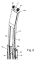
- the stanchion 7 consists of an upper stake part 11 and a lower one Rung part 12, which are formed such that they are relative to each other displaced and thus the stanchions 7 in the production variable in height are.
- the upper Rungenteil 11 has a hole 13, in the one Lock bolt 14 of the lower Rungenteils 12 engages and thus the height of the Runge 7 determines. Through the hole 13 and the locking bolt 14 it is possible, from standardized upper stake part 11 and lower stake part 12 stanchions to produce 7 different heights without this in each case other parts are needed.
- the lower Rungenteil 12 has in the region of its connection with the upper Rung part 11 a flat shape, the two rectangular projections 15th has, in the respective corresponding elevations 16 of the upper Rurgiteils 11 intervene. As a result, a good transmission of forces and moments of the lower Rurgiteils 12 ensures the upper stake part 11.
- the connection of the two rungs parts 11, 12 is the back of the Projections 15 with a cover plate 12 a, which at the lower stake part 12 is screwed tight, closed.
- the upper rungs portion 11 in its upper portion a T-shaped extension 17, in whose Ends two double rollers 18 are mounted, which in a career of the Longitudinal member 6 intervene.
- This can be unlocked Runge 7 through the Rolls of rollers 18 these are moved along the longitudinal member 6.
- One Supporting portion 11a of the upper Rurgiteils 11 is a flat horizontal support trained and destined, after raising the stanchion 7 in Appendix to get against a lower flat side of the associated side member 6, whereby the rollers 18 are relieved at locked Runge 7 and also one possibly existing deflection of the longitudinal member 6 counteracted becomes.
- the stanchion 7 with its lower portion on the Attachment member 10 is raised and locked so that the forces be introduced vertically into the Runge 7 and also lateral or vertical play is avoided.
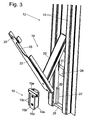
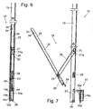
- the intermediate lever 20 is on the one hand at the bottom Rung part between the two rectangular projections 15 in the area a fixing unit 21a in a hinge 21 and at the other end the main lever 22 via a hinge 23, wherein the short lever arm 22a of the main lever 22 end a claw portion 24 has, and the long Lever 22b of the main lever 22 has a handle recess 25 at its the Joint 23 facing away from the end.
- the claw part 24 is at a solid support member 29 set.
- the stanchion 3 has at its lower Rungenteil 12th a crosspiece 26, which is the area between the two projections 15 connects with each other and at the same time opposite the front sides of the Projections 15 springs back.
- the crossbar 26 limits a Recess 30 in the foot region of the lower Rungenteils 12 down.
- the Recess is dimensioned so that the stanchion 7 there over the fastener 10 can be pushed.
- Vertical and in the region of the projections 15 are further arranged on both sides of the transverse web 26 upstanding struts 27, the opposite the bridge 26 jump back another piece.
- an abutment 28 in the form of a block made of metal, which is centered between the two projections 15 on the welded lower rung portion 12 or other suitable manner is attached.
- the anvil 28 is about as wide as the support member 29 or the attachment member 10. Between the anvil 28 and the Projections 15 each have a gap 31 is provided.
- the distance between Cross bar 26 and thrust bearing 28 corresponds approximately to the common height of Support member 29 and attachment member 10th
- the support member 29 is by welding or preferably by Screw firmly connected to the main lever 22. At the same time is in the Support member 28 and the bearing of the joint 23 is provided. Alternatively could the articulation with the joint 23 also on another part of Main lever 22 may be provided, the outside of the support member 29th is arranged, for example in one area (with locked Runge 7) above the anvil 28.
- the support member 29 has the top of the Attachment member 10 and the underside of the thrust bearing 28 facing Bounding surfaces which are adapted to this in shape, present So flat boundary surfaces. It is possible that the lower Rieuxteil 12th To round off facing corners of the support member 29. For attachment of the Klauenteils 24, the support member 29 is slightly less thick than that for Available depth of the recess 30 configured.
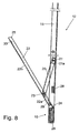
- the claw part 24 is intended behind the head 10e of the T-shaped Metal part 10b to grab and with its end-side turn first to hook the main lever 22 in the attachment member 10.
- the car 17th mounted in the side member 6 and the recess 30 of the stanchion 7 via the fastening member 10 passed over in such a way that the transverse web 26 itself behind and below the downwardly projecting nose 10d of the T-shaped Metal part 10 b is located and the struts 27, the U-shaped metal part 10 a laterally frame.
- the knee lever assembly 19 is raised or pivoted upwards. This can be done by hand, in In the present embodiment, this is a leaf spring 32nd provided on the intermediate lever 22 and on the lower Rurgiteil 12th is fixed and spreads them apart.
- the claw part 24 is in the upper slot of the attachment member 10, of the parts 10 a, 10 b is introduced, as shown in Fig. 4 and Fig. 8 is introduced. Due to the toggle lever assembly 19 is then by pressing the Main lever 22, for example in the area of the handle unit 25, toward the body of the lower Rungenteils 12 Runge 7 raised. The forces for the raising of the stanchion 7 are during the operation of the Lever assembly 19 via the two joints 21, 23 of the Attachment member 10 on the stanchion 7 and the stanchion 7 on the Transposed longitudinal member 6.
- the support element 29 is integrally formed and a slightly narrower lower section and a slightly wider upper section Section, wherein the upper portion at the same time a bearing for the Joint 23 has. It is possible, the joint 23 also elsewhere to provide and the support member 29 as a part of uniform thickness train. It is also possible to use the two sections as adjacent To design parts of a multi-part support element, whereby the production large quantities becomes more economical, even if this causes the Increase tolerances of the support element. Due to the greater width of the Upper section of the support element will be good for the reliable Supporting the stanchion 7 advantageous overlap with the anvil 28th achieved.
- the main lever 22 has in the end part of its long lever arm 22 b in approximately rectangular cutout 33, to which a lowered portion 34th adjoined.
- a (not shown) snap the lowered portion 34 and holds the Main lever 22 releasably attached to the lower Rungenteil 12.
- the snap device has a Release button, which is moved up to release the latch can be.
- the punching 33 is advantageous in the vicinity of the Grip recess 25 arranged that the thumb of an operator Solenoid button can operate while the hand, the handle recess 25th be upheld. Since the lever assembly 19 in the locked state of Runge. 7 force-free, the snap device can absorb small forces be designed so that the one-handed operation of the lever assembly 19th is possible.
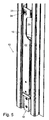
- Fig. 12 and 13 it can be seen that the foot portion of the lower Rungenteils 12 of the stanchion 7 at least in a region surrounding the recess 30, is additionally reinforced, although the profile in the form of a double C defining projections 15 already to the lower end of the lower Rung part 12 continued uninterrupted and thus a favorable Transmission of vertical forces allows.
- the crosspiece 26 and the struts 27 are formed as a common group, either by welding or as a common casting, and in the foot area the stanchion 7 are welded. In this case, the transverse web 26 reaches a thickness, which accounts for more than half the depth of the projections 15.
- angle profiles 35 are welded, which extends into the area of Counter bearing 28 rich and thus the projections 15 in addition stiffen.
- the end of the free leg of the angle section 35 is in a short decency to the inside of the outer walls 15a of the Projections 15 arranged. It is possible to pick up this distance and the back of the projections 15 to close completely.
- the angle profiles 35 may also be welded to the struts 27.
- a Assembly of cross bar 26, struts 27 and angle sections 35, possibly even with the counter bearing 28, be made of one piece and in the foot of the Runge 7 are welded.
- the invention is based on a stanchion with a support element 28 above been described, which has a flat bottom for resting on the plane Upper side of the fastening member 10, and in which a claw part 24th penetrates into a slot of the fastening member 10.
- a support element 28 above has a flat bottom for resting on the plane Upper side of the fastening member 10, and in which a claw part 24th penetrates into a slot of the fastening member 10.
- Support member one to the contour of the upper side of the fastening member 10th Complementary stage, for example, when the attachment member 10 has an upwardly projecting nose similar to the nose 10d, wherein the grading in the corresponding, e.g. as a stemming member trained support member also recognized the main lever low can be.
Landscapes
- Engineering & Computer Science (AREA)
- Chemical & Material Sciences (AREA)
- Combustion & Propulsion (AREA)
- Transportation (AREA)
- Mechanical Engineering (AREA)
- Handcart (AREA)
- Refuge Islands, Traffic Blockers, Or Guard Fence (AREA)
- Body Structure For Vehicles (AREA)
- Tents Or Canopies (AREA)
- Emergency Lowering Means (AREA)
- Seats For Vehicles (AREA)
- Fittings On The Vehicle Exterior For Carrying Loads, And Devices For Holding Or Mounting Articles (AREA)
- Saccharide Compounds (AREA)
- Steroid Compounds (AREA)
Claims (23)
- Montant pour une structure à bâche qui peut être verrouillé à un élément de fixation (10), ledit montant comportant un dispositif à levier (19) destiné à lever et verrouiller le montant, caractérisé en ce que le montant comporte une butée (28), et en ce qu'un élément de support (29) est prévu, lequel peut être inséré entre l'élément de fixation (10) et la butée (28),
de sorte que lorsque le montant est verrouillé, des articulations (21, 23) du dispositif à levier (19) ne transmettent aucune force verticale. - Montant selon la revendication 1, caractérisé en ce que l'élément de support (29) comporte une butée de limitation inférieure qui est adaptée par complémentarité de forme à l'élément de fixation (10) et une butée de limitation supérieure qui est adaptée par complémentarité de forme à la butée (28).
- Montant selon la revendication 1 ou 2, caractérisé en ce que l'élément de support (29) est fixé à une partie du montant.
- Montant selon la revendication 1 ou 2, caractérisé en ce que l'élément de support est fixé à l'élément de fixation (10).
- Montant selon la revendication 1 ou 2, caractérisé en ce que l'élément de support est une partie complémentaire du montant et de l'élément de fixation (10).
- Montant selon l'une des revendications 1 à 3, caractérisé en ce que l'élément de support (29) est placé sur le dispositif à levier (19).
- Montant selon la revendication 6, caractérisé en ce que le dispositif à levier (19) comporte un levier principal (22), auquel est fixé l'élément de support (29), et un levier auxiliaire (20) qui relie le levier principal (22) et le corps du montant.
- Montant selon la revendication 7, caractérisé en ce que le levier intermédiaire (20) et le levier principal (22) sont conformés sensiblement en pièces en forme de U s'engageant l'une dans l'autre lorsque le montant est à l'état verrouillé.
- Montant selon la revendication 8, caractérisé en ce que l'élément de support (29) et la butée (28) sont recouverts par une base d'au moins un des leviers en forme de U (20, 22) lorsque le montant est à l'état verrouillé.
- Montant selon l'une des revendications 7 à 9, caractérisé en ce que le levier principal (22) comporte un évidement de préhension (25) ménagé au-dessus de son articulation (23) pour le levier auxiliaire (20).
- Montant selon l'une des revendications 1 à 10, caractérisé en ce que le dispositif à levier (19) comporte une partie en forme de griffe (24) qui peut être amenée en engagement avec l'élément de fixation (10).
- Montant selon l'une des revendications 1 à 11, caractérisé en ce que le montant comporte un évidement (30) qui est ménagé au-dessous de la butée (28) dans lequel l'élément de support (29) peut être inséré.
- Montant selon l'une des revendications 1 à 12, caractérisé en ce que le montant comporte au niveau de son pied une entretoise (26) qui s'engage, à l'état verrouillé, derrière un taquet (10d) de l'élément de fixation (10).
- Montant selon l'une des revendications 1 à 13, caractérisé en ce que le montant comporte au niveau de son pied des contrefiches (27) s'étendant verticalement, qui sont espacées l'une de l'autre d'une distance correspondant à la largeur de l'élément de fixation (10).
- Montant selon la revendication 13 et 14, caractérisé en ce que l'entretoise (26) et les contrefiches (27) sont conformées en une partie commune.
- Montant selon l'une des revendications 1 à 15, caractérisé en ce que la butée (28) limite vers le haut un évidement (30) du montant.
- Montant selon l'une des revendications 1 à 16, caractérisé en ce que le montant est constitué d'une partie de montant supérieure (11) et d'une partie de montant inférieure (12) qui s'engagent l'une dans l'autre.
- Montant selon la revendication 17, caractérisé en ce que la partie de montant inférieure (12) présente un profil doté de saillies (15) qui s'étendent dans la direction longitudinale du montant et qui présentent un profil rectangulaire.
- Montant selon l'une des revendications 1 à 18, caractérisé en ce qu'une surface d'appui (11a) est prévue qui vient en contact avec un support longitudinal (6) lorsque le montant est soulevé et en ce qu'un prolongement (17), doté de galets (18), fait saillie au-dessus de la surface d'appui (11a).
- Montant selon l'une des revendications 1 à 19, caractérisé en ce que la butée (28) est conformée en corps métallique de liaison fixé au corps du montant.
- Dispositif à montant, comportant un élément de fixation (10) et un montant (7) selon l'une des revendications 1 à 20, amovible par rapport à l'élément de fixation.
- Bâti de capote pour surface de chargement (4) recouverte d'une structure à bâche, lequel bâti de capote comporte des longerons (6) s'étendant au-dessus des bords de la surface de chargement (4),
caractérisé par un dispositif à montant selon la revendication 21 dans lequel l'élément de fixation (10) est fixé au niveau de la surface chargement (4) et le montant (6) est verrouillé au niveau de son pied à l'élément de fixation (10) et appuie au niveau d'une surface d'appui supérieure (11a) contre les longerons correspondants (6). - Bâti de capote selon la revendication 22, caractérisé en ce que la structure à bâche est conformée en capote coulissante.
Applications Claiming Priority (3)
| Application Number | Priority Date | Filing Date | Title |
|---|---|---|---|
| DE10228982A DE10228982A1 (de) | 2002-06-28 | 2002-06-28 | Runge |
| DE10228982 | 2002-06-28 | ||
| PCT/DE2003/002054 WO2004002803A2 (fr) | 2002-06-28 | 2003-06-20 | Etançon |
Publications (2)
| Publication Number | Publication Date |
|---|---|
| EP1517824A2 EP1517824A2 (fr) | 2005-03-30 |
| EP1517824B1 true EP1517824B1 (fr) | 2005-08-03 |
Family
ID=29723529
Family Applications (1)
| Application Number | Title | Priority Date | Filing Date |
|---|---|---|---|
| EP03761420A Expired - Lifetime EP1517824B1 (fr) | 2002-06-28 | 2003-06-20 | Etancon |
Country Status (7)
| Country | Link |
|---|---|
| US (1) | US8360512B2 (fr) |
| EP (1) | EP1517824B1 (fr) |
| CN (1) | CN100376447C (fr) |
| AT (1) | ATE301068T1 (fr) |
| DE (2) | DE10228982A1 (fr) |
| PL (1) | PL207293B1 (fr) |
| WO (1) | WO2004002803A2 (fr) |
Cited By (2)
| Publication number | Priority date | Publication date | Assignee | Title |
|---|---|---|---|---|
| EP1935763A1 (fr) | 2006-12-22 | 2008-06-25 | F. HESTERBERG & SÖHNE GmbH & Co. KG | Rancher pour une ouverture de chargement refermable d'une superstructure de véhicule |
| EP1953068A1 (fr) | 2006-05-06 | 2008-08-06 | F. HESTERBERG & SÖHNE GmbH & Co. KG | Ranche pour constructions automobiles |
Families Citing this family (17)
| Publication number | Priority date | Publication date | Assignee | Title |
|---|---|---|---|---|
| ES2285896B1 (es) * | 2005-04-19 | 2008-08-16 | Mecadetol, S.A | Cierre plegable para cajas de carga. |
| DE202005017458U1 (de) * | 2005-11-09 | 2005-12-29 | F. Hesterberg & Söhne GmbH & Co KG | Runge für einen Nutzfahrzeug- oder Anhängerdachaufbau |
| CN1317183C (zh) * | 2005-12-23 | 2007-05-23 | 中国石化集团南京设计院 | 利用中低品位磷矿生产湿法磷酸的方法 |
| DE102006018608A1 (de) * | 2006-04-21 | 2007-10-25 | F. Hesterberg & Söhne Gmbh & Co. Kg | Runge für die Ladeöffnung eines Fahrzeugaufbaus |
| DE102007007064A1 (de) | 2007-02-08 | 2008-08-14 | F. Hesterberg & Söhne GmbH & Co KG | Schließanordnung für einen Fahrzeugbau |
| US7578539B1 (en) | 2008-05-05 | 2009-08-25 | Roland Curtains Usa, Inc. | Apparatus for decreasing opening velocities of support pillars |
| US7942472B2 (en) * | 2009-03-23 | 2011-05-17 | Western Trailer Co. | Clamping side post for curtain side trailer |
| ES1071092Y (es) * | 2009-09-21 | 2010-04-07 | Mecadetol Sa | Poste para cierres laterales de cajas de carga |
| DE102010037515A1 (de) * | 2010-09-14 | 2012-03-15 | F. Hesterberg & Söhne Gmbh & Co. Kg | Schließanordnung für einen Fahrzeugaufbau |
| DE102010061356A1 (de) * | 2010-12-20 | 2012-06-21 | F. Hesterberg & Söhne Gmbh & Co. Kg | Runge für einen Fahrzeugaufbau, insbesondere einen Nutzfahrzeugaufbau |
| DE102013108858A1 (de) * | 2013-08-15 | 2015-02-19 | F. Hesterberg & Söhne Gmbh & Co. Kg | Seitenabdeckung eines Nutzfahrzeugaufbaus |
| PL230082B1 (pl) | 2014-12-31 | 2018-09-28 | Wielton Spolka Akcyjna | Podpora słupka naczepy |
| AU2016216713B2 (en) * | 2015-08-19 | 2021-03-11 | Australian Trailer Solutions Group Property Pty Ltd | A roof support and/or freight restraint for a vehicle or container |
| DE202016000463U1 (de) * | 2016-01-26 | 2016-03-09 | Helmut Fliegl | Runge für einen Nutzfahrzeug- oder Anhängeraufbau |
| SE539883C2 (sv) * | 2016-05-18 | 2018-01-02 | Rosén Göran | Anordning vid sidostolpe för lastflak |
| TR201816226A2 (tr) * | 2018-10-31 | 2018-11-21 | Emre Oemer Okumus | Kayar mekani̇zmali dorse babasi |
| EP3964429A1 (fr) * | 2020-09-02 | 2022-03-09 | Schmitz Cargobull AG | Structure de bâche et véhicule utilitaire pourvu de bâche à panneaux |
Family Cites Families (21)
| Publication number | Priority date | Publication date | Assignee | Title |
|---|---|---|---|---|
| SE328792B (fr) * | 1968-11-15 | 1970-09-21 | G Rosen | |
| CA985474A (en) * | 1972-10-12 | 1976-03-16 | Steel Equipment Company Limited | Frame joint |
| US4452234A (en) * | 1982-02-19 | 1984-06-05 | Cities Service Company | Collapsible mobile solar energy power source |
| US4421943A (en) * | 1982-02-19 | 1983-12-20 | Cities Service Company | Collapsible mobile solar energy power source |
| US4952009A (en) * | 1987-06-29 | 1990-08-28 | Morgan Corporation | Curtained doors for vehicle bodies |
| CN2033364U (zh) * | 1988-05-01 | 1989-03-01 | 王友坚 | 折叠式货车篷 |
| CN2133484Y (zh) * | 1992-09-22 | 1993-05-19 | 陈兴全 | 推拉折叠式汽车车篷 |
| US5658037A (en) * | 1994-03-31 | 1997-08-19 | Evans; Jeffrey L. | Retractable closure system |
| DE29616344U1 (de) * | 1996-09-19 | 1996-11-14 | Hesterberg & Soehne Gmbh & Co | Hängerunge |
| DE19839769A1 (de) * | 1998-09-01 | 2000-03-02 | Edscha Lkw Schiebeverdeck Gmbh | Planenbefestigung an Verdecken für Nutzfahrzeuge |
| DE19839775A1 (de) * | 1998-09-01 | 2000-03-02 | Edscha Lkw Schiebeverdeck Gmbh | Faltbarer Planenaufbau für Fahrzeugaufbauten und Container |
| DE19913616A1 (de) * | 1999-03-25 | 2000-10-05 | Sommer Fahrzeugbau Gmbh & Co K | Schiebeplanen-Aufbau |
| FR2802867B1 (fr) * | 1999-12-24 | 2002-04-12 | Sofaco Soc Fab Comm | Dispositif de securite pour ranchers pour l'ouverture de baches de camions |
| DE20000002U1 (de) * | 2000-01-03 | 2000-04-06 | Hesterberg & Soehne Gmbh & Co | Hängerunge für Lastfahrzeuge |
| DE20000004U1 (de) * | 2000-01-03 | 2000-04-06 | Hesterberg & Soehne Gmbh & Co | Hängerunge für Lastfahrzeuge |
| CN2423154Y (zh) * | 2000-05-18 | 2001-03-14 | 姚天锡 | 一种有可展叠式篷布的货车 |
| WO2002004277A1 (fr) * | 2000-07-12 | 2002-01-17 | Plus Systems Martin Bruckner Gmbh | Structure pour compartiment de chargement a montants entre sol et toit |
| DE20205984U1 (de) * | 2002-04-16 | 2002-08-01 | Load Lok Deutschland Gmbh | Runge, insbesondere Klapprunge, mit Riegeleinrichtung |
| CN2551510Y (zh) * | 2002-06-15 | 2003-05-21 | 青岛特种汽车集团公司 | 车厢展篷 |
| DE20301201U1 (de) * | 2003-01-27 | 2003-04-30 | Lorenz Gillhuber Transporte Un | Runge mit integrierter Vorrichtung zur Ladungssicherung, insbesondere für Transportfahrzeuge mit Planenaufbauten |
| DE202005018342U1 (de) * | 2005-11-22 | 2006-12-28 | Edscha Lkw-Schiebeverdecke Gmbh | Runge für einen Planenaufbau |
-
2002
- 2002-06-28 DE DE10228982A patent/DE10228982A1/de not_active Withdrawn
-
2003
- 2003-06-20 US US10/518,187 patent/US8360512B2/en not_active Expired - Fee Related
- 2003-06-20 EP EP03761420A patent/EP1517824B1/fr not_active Expired - Lifetime
- 2003-06-20 CN CNB038153912A patent/CN100376447C/zh not_active Expired - Fee Related
- 2003-06-20 DE DE50300921T patent/DE50300921D1/de not_active Expired - Lifetime
- 2003-06-20 AT AT03761420T patent/ATE301068T1/de not_active IP Right Cessation
- 2003-06-20 WO PCT/DE2003/002054 patent/WO2004002803A2/fr active IP Right Grant
- 2003-06-20 PL PL373248A patent/PL207293B1/pl unknown
Cited By (2)
| Publication number | Priority date | Publication date | Assignee | Title |
|---|---|---|---|---|
| EP1953068A1 (fr) | 2006-05-06 | 2008-08-06 | F. HESTERBERG & SÖHNE GmbH & Co. KG | Ranche pour constructions automobiles |
| EP1935763A1 (fr) | 2006-12-22 | 2008-06-25 | F. HESTERBERG & SÖHNE GmbH & Co. KG | Rancher pour une ouverture de chargement refermable d'une superstructure de véhicule |
Also Published As
| Publication number | Publication date |
|---|---|
| EP1517824A2 (fr) | 2005-03-30 |
| CN100376447C (zh) | 2008-03-26 |
| PL207293B1 (pl) | 2010-11-30 |
| US8360512B2 (en) | 2013-01-29 |
| ATE301068T1 (de) | 2005-08-15 |
| WO2004002803A2 (fr) | 2004-01-08 |
| PL373248A1 (en) | 2005-08-22 |
| DE50300921D1 (en) | 2005-09-08 |
| WO2004002803A3 (fr) | 2004-04-08 |
| DE10228982A1 (de) | 2004-01-15 |
| CN1665712A (zh) | 2005-09-07 |
| US20050231004A1 (en) | 2005-10-20 |
Similar Documents
| Publication | Publication Date | Title |
|---|---|---|
| EP1517824B1 (fr) | Etancon | |
| EP2080654B2 (fr) | Berceau de couverture pour un montage de superstructure | |
| EP3572258B1 (fr) | Superctructure de bâche | |
| EP2313303B1 (fr) | Rancher avec dispositif de verrouillage | |
| EP1787842A2 (fr) | Rancher pour structure de couverture | |
| DE202013001846U1 (de) | Verdeckgestell für einen Planenaufbau sowie Schaftteil und Schlitten | |
| DE102020102186B4 (de) | Verschlusssystem zur lösbaren Befestigung einer Runge an ein Nutzfahrzeug | |
| DE10312638B4 (de) | Verfahren und Vorrichtung zur Ladungssicherung | |
| DE19714678C2 (de) | Schieberunge | |
| DE3900455C2 (de) | Dachkoffer für Kraftfahrzeuge | |
| DE102013003222A1 (de) | Verdeckgestell für einen Planenaufbau sowie Schaftteil und Schlitten | |
| DE4011624A1 (de) | Geruestboden | |
| EP3106329A1 (fr) | Carrosserie de vehicule, en particulier pour vehicules utilitaires, vehicule utilitaire comprenant une telle carrosserie et procede de fabrication | |
| DE19706493A1 (de) | LKW-Aufbau | |
| DE2900055C2 (de) | Runge für ein Lastfahrzeug | |
| DE102014008949B4 (de) | Planenaufbau | |
| DE202008012966U1 (de) | Aufbau für ein Transportfahrzeug und mit einem solchen Aufbau versehener Sattelzug | |
| DE19545616C1 (de) | Klapprunge für Lastfahrzeuge | |
| EP0596305B1 (fr) | Système de fermeture | |
| DE10238785A1 (de) | Aufbau für Lastfahrzeuge | |
| DE202008000812U1 (de) | Runge mit Riegeleinrichtung | |
| DE102005033319A1 (de) | Einrichtung zum Festlegen einer Runge im Bereich eines Nutzfahrzeugaufbaus | |
| DE3919349C2 (fr) | ||
| DE3220859A1 (de) | Zusammenklappbarer langgut-container | |
| EP2465756A2 (fr) | Ranche pour un montage de véhicule, notamment un montage de véhicule utilitaire |
Legal Events
| Date | Code | Title | Description |
|---|---|---|---|
| PUAI | Public reference made under article 153(3) epc to a published international application that has entered the european phase |
Free format text: ORIGINAL CODE: 0009012 |
|
| 17P | Request for examination filed |
Effective date: 20041211 |
|
| AK | Designated contracting states |
Kind code of ref document: A2 Designated state(s): AT BE BG CH CY CZ DE DK EE ES FI FR GB GR HU IE IT LI LU MC NL PT RO SE SI SK TR |
|
| GRAP | Despatch of communication of intention to grant a patent |
Free format text: ORIGINAL CODE: EPIDOSNIGR1 |
|
| GRAS | Grant fee paid |
Free format text: ORIGINAL CODE: EPIDOSNIGR3 |
|
| GRAA | (expected) grant |
Free format text: ORIGINAL CODE: 0009210 |
|
| AK | Designated contracting states |
Kind code of ref document: B1 Designated state(s): AT BE BG CH CY CZ DE DK EE ES FI FR GB GR HU IE IT LI LU MC NL PT RO SE SI SK TR |
|
| PG25 | Lapsed in a contracting state [announced via postgrant information from national office to epo] |
Ref country code: SI Free format text: LAPSE BECAUSE OF FAILURE TO SUBMIT A TRANSLATION OF THE DESCRIPTION OR TO PAY THE FEE WITHIN THE PRESCRIBED TIME-LIMIT Effective date: 20050803 Ref country code: EE Free format text: LAPSE BECAUSE OF FAILURE TO SUBMIT A TRANSLATION OF THE DESCRIPTION OR TO PAY THE FEE WITHIN THE PRESCRIBED TIME-LIMIT Effective date: 20050803 Ref country code: GB Free format text: LAPSE BECAUSE OF FAILURE TO SUBMIT A TRANSLATION OF THE DESCRIPTION OR TO PAY THE FEE WITHIN THE PRESCRIBED TIME-LIMIT Effective date: 20050803 Ref country code: IE Free format text: LAPSE BECAUSE OF FAILURE TO SUBMIT A TRANSLATION OF THE DESCRIPTION OR TO PAY THE FEE WITHIN THE PRESCRIBED TIME-LIMIT Effective date: 20050803 Ref country code: NL Free format text: LAPSE BECAUSE OF FAILURE TO SUBMIT A TRANSLATION OF THE DESCRIPTION OR TO PAY THE FEE WITHIN THE PRESCRIBED TIME-LIMIT Effective date: 20050803 Ref country code: RO Free format text: LAPSE BECAUSE OF FAILURE TO SUBMIT A TRANSLATION OF THE DESCRIPTION OR TO PAY THE FEE WITHIN THE PRESCRIBED TIME-LIMIT Effective date: 20050803 Ref country code: SK Free format text: LAPSE BECAUSE OF FAILURE TO SUBMIT A TRANSLATION OF THE DESCRIPTION OR TO PAY THE FEE WITHIN THE PRESCRIBED TIME-LIMIT Effective date: 20050803 Ref country code: FI Free format text: LAPSE BECAUSE OF FAILURE TO SUBMIT A TRANSLATION OF THE DESCRIPTION OR TO PAY THE FEE WITHIN THE PRESCRIBED TIME-LIMIT Effective date: 20050803 |
|
| REG | Reference to a national code |
Ref country code: GB Ref legal event code: FG4D Free format text: NOT ENGLISH |
|
| REG | Reference to a national code |
Ref country code: CH Ref legal event code: EP |
|
| REG | Reference to a national code |
Ref country code: IE Ref legal event code: FG4D Free format text: LANGUAGE OF EP DOCUMENT: GERMAN |
|
| REF | Corresponds to: |
Ref document number: 50300921 Country of ref document: DE Date of ref document: 20050908 Kind code of ref document: P |
|
| PG25 | Lapsed in a contracting state [announced via postgrant information from national office to epo] |
Ref country code: DK Free format text: LAPSE BECAUSE OF FAILURE TO SUBMIT A TRANSLATION OF THE DESCRIPTION OR TO PAY THE FEE WITHIN THE PRESCRIBED TIME-LIMIT Effective date: 20051103 Ref country code: BG Free format text: LAPSE BECAUSE OF FAILURE TO SUBMIT A TRANSLATION OF THE DESCRIPTION OR TO PAY THE FEE WITHIN THE PRESCRIBED TIME-LIMIT Effective date: 20051103 Ref country code: SE Free format text: LAPSE BECAUSE OF FAILURE TO SUBMIT A TRANSLATION OF THE DESCRIPTION OR TO PAY THE FEE WITHIN THE PRESCRIBED TIME-LIMIT Effective date: 20051103 Ref country code: GR Free format text: LAPSE BECAUSE OF FAILURE TO SUBMIT A TRANSLATION OF THE DESCRIPTION OR TO PAY THE FEE WITHIN THE PRESCRIBED TIME-LIMIT Effective date: 20051103 |
|
| PG25 | Lapsed in a contracting state [announced via postgrant information from national office to epo] |
Ref country code: PT Free format text: LAPSE BECAUSE OF FAILURE TO SUBMIT A TRANSLATION OF THE DESCRIPTION OR TO PAY THE FEE WITHIN THE PRESCRIBED TIME-LIMIT Effective date: 20060103 |
|
| NLV1 | Nl: lapsed or annulled due to failure to fulfill the requirements of art. 29p and 29m of the patents act | ||
| PG25 | Lapsed in a contracting state [announced via postgrant information from national office to epo] |
Ref country code: HU Free format text: LAPSE BECAUSE OF FAILURE TO SUBMIT A TRANSLATION OF THE DESCRIPTION OR TO PAY THE FEE WITHIN THE PRESCRIBED TIME-LIMIT Effective date: 20060204 |
|
| GBV | Gb: ep patent (uk) treated as always having been void in accordance with gb section 77(7)/1977 [no translation filed] |
Effective date: 20050803 |
|
| REG | Reference to a national code |
Ref country code: IE Ref legal event code: FD4D |
|
| PLBE | No opposition filed within time limit |
Free format text: ORIGINAL CODE: 0009261 |
|
| STAA | Information on the status of an ep patent application or granted ep patent |
Free format text: STATUS: NO OPPOSITION FILED WITHIN TIME LIMIT |
|
| PG25 | Lapsed in a contracting state [announced via postgrant information from national office to epo] |
Ref country code: BE Free format text: LAPSE BECAUSE OF NON-PAYMENT OF DUE FEES Effective date: 20060630 Ref country code: MC Free format text: LAPSE BECAUSE OF NON-PAYMENT OF DUE FEES Effective date: 20060630 |
|
| 26N | No opposition filed |
Effective date: 20060504 |
|
| EN | Fr: translation not filed | ||
| PG25 | Lapsed in a contracting state [announced via postgrant information from national office to epo] |
Ref country code: FR Free format text: LAPSE BECAUSE OF FAILURE TO SUBMIT A TRANSLATION OF THE DESCRIPTION OR TO PAY THE FEE WITHIN THE PRESCRIBED TIME-LIMIT Effective date: 20060929 |
|
| PG25 | Lapsed in a contracting state [announced via postgrant information from national office to epo] |
Ref country code: AT Free format text: LAPSE BECAUSE OF NON-PAYMENT OF DUE FEES Effective date: 20060620 |
|
| BERE | Be: lapsed |
Owner name: EDSCHA LKW-SCHIEBEVERDECKE G.M.B.H. Effective date: 20060630 |
|
| REG | Reference to a national code |
Ref country code: CH Ref legal event code: PL |
|
| PG25 | Lapsed in a contracting state [announced via postgrant information from national office to epo] |
Ref country code: LI Free format text: LAPSE BECAUSE OF NON-PAYMENT OF DUE FEES Effective date: 20070630 Ref country code: CH Free format text: LAPSE BECAUSE OF NON-PAYMENT OF DUE FEES Effective date: 20070630 |
|
| PG25 | Lapsed in a contracting state [announced via postgrant information from national office to epo] |
Ref country code: LU Free format text: LAPSE BECAUSE OF NON-PAYMENT OF DUE FEES Effective date: 20060620 |
|
| PG25 | Lapsed in a contracting state [announced via postgrant information from national office to epo] |
Ref country code: CY Free format text: LAPSE BECAUSE OF FAILURE TO SUBMIT A TRANSLATION OF THE DESCRIPTION OR TO PAY THE FEE WITHIN THE PRESCRIBED TIME-LIMIT Effective date: 20050803 Ref country code: FR Free format text: LAPSE BECAUSE OF FAILURE TO SUBMIT A TRANSLATION OF THE DESCRIPTION OR TO PAY THE FEE WITHIN THE PRESCRIBED TIME-LIMIT Effective date: 20050803 |
|
| PG25 | Lapsed in a contracting state [announced via postgrant information from national office to epo] |
Ref country code: ES Free format text: LAPSE BECAUSE OF NON-PAYMENT OF DUE FEES Effective date: 20060630 |
|
| PGFP | Annual fee paid to national office [announced via postgrant information from national office to epo] |
Ref country code: CZ Payment date: 20160620 Year of fee payment: 14 |
|
| PG25 | Lapsed in a contracting state [announced via postgrant information from national office to epo] |
Ref country code: CZ Free format text: LAPSE BECAUSE OF NON-PAYMENT OF DUE FEES Effective date: 20170620 |
|
| PGFP | Annual fee paid to national office [announced via postgrant information from national office to epo] |
Ref country code: TR Payment date: 20200619 Year of fee payment: 18 |
|
| PGFP | Annual fee paid to national office [announced via postgrant information from national office to epo] |
Ref country code: IT Payment date: 20200625 Year of fee payment: 18 |
|
| PGFP | Annual fee paid to national office [announced via postgrant information from national office to epo] |
Ref country code: DE Payment date: 20210618 Year of fee payment: 19 |
|
| PG25 | Lapsed in a contracting state [announced via postgrant information from national office to epo] |
Ref country code: IT Free format text: LAPSE BECAUSE OF NON-PAYMENT OF DUE FEES Effective date: 20210620 |
|
| REG | Reference to a national code |
Ref country code: DE Ref legal event code: R119 Ref document number: 50300921 Country of ref document: DE |
|
| PG25 | Lapsed in a contracting state [announced via postgrant information from national office to epo] |
Ref country code: DE Free format text: LAPSE BECAUSE OF NON-PAYMENT OF DUE FEES Effective date: 20230103 |