EP1517824B1 - Stanchion - Google Patents
Stanchion Download PDFInfo
- Publication number
- EP1517824B1 EP1517824B1 EP03761420A EP03761420A EP1517824B1 EP 1517824 B1 EP1517824 B1 EP 1517824B1 EP 03761420 A EP03761420 A EP 03761420A EP 03761420 A EP03761420 A EP 03761420A EP 1517824 B1 EP1517824 B1 EP 1517824B1
- Authority
- EP
- European Patent Office
- Prior art keywords
- stanchion
- lever
- fixing member
- runge
- supporting element
- Prior art date
- Legal status (The legal status is an assumption and is not a legal conclusion. Google has not performed a legal analysis and makes no representation as to the accuracy of the status listed.)
- Expired - Lifetime
Links
- 239000002184 metal Substances 0.000 claims description 23
- 210000000078 claw Anatomy 0.000 claims description 7
- 210000002414 leg Anatomy 0.000 description 5
- 238000003825 pressing Methods 0.000 description 4
- 238000012546 transfer Methods 0.000 description 4
- 230000005540 biological transmission Effects 0.000 description 3
- 238000013461 design Methods 0.000 description 3
- 238000003780 insertion Methods 0.000 description 3
- 230000037431 insertion Effects 0.000 description 3
- 238000004519 manufacturing process Methods 0.000 description 3
- 238000003466 welding Methods 0.000 description 3
- 238000010276 construction Methods 0.000 description 2
- 210000003127 knee Anatomy 0.000 description 2
- 238000012549 training Methods 0.000 description 2
- 238000010009 beating Methods 0.000 description 1
- 238000005452 bending Methods 0.000 description 1
- 239000000969 carrier Substances 0.000 description 1
- 238000005266 casting Methods 0.000 description 1
- 230000000295 complement effect Effects 0.000 description 1
- 230000001419 dependent effect Effects 0.000 description 1
- 238000011161 development Methods 0.000 description 1
- 238000006073 displacement reaction Methods 0.000 description 1
- 238000004090 dissolution Methods 0.000 description 1
- 230000002349 favourable effect Effects 0.000 description 1
- 238000009432 framing Methods 0.000 description 1
- 230000000977 initiatory effect Effects 0.000 description 1
- 238000012986 modification Methods 0.000 description 1
- 230000004048 modification Effects 0.000 description 1
- 230000035515 penetration Effects 0.000 description 1
- 239000002985 plastic film Substances 0.000 description 1
- 229920006255 plastic film Polymers 0.000 description 1
- 230000002028 premature Effects 0.000 description 1
- 238000004080 punching Methods 0.000 description 1
- 230000002787 reinforcement Effects 0.000 description 1
- 230000000284 resting effect Effects 0.000 description 1
- 238000009420 retrofitting Methods 0.000 description 1
- 238000000926 separation method Methods 0.000 description 1
- 239000007787 solid Substances 0.000 description 1
- 239000011343 solid material Substances 0.000 description 1
- 210000003813 thumb Anatomy 0.000 description 1
- 230000003313 weakening effect Effects 0.000 description 1
Images


Classifications
-
- B—PERFORMING OPERATIONS; TRANSPORTING
- B62—LAND VEHICLES FOR TRAVELLING OTHERWISE THAN ON RAILS
- B62D—MOTOR VEHICLES; TRAILERS
- B62D33/00—Superstructures for load-carrying vehicles
- B62D33/02—Platforms; Open load compartments
- B62D33/0222—Connecting elements between stanchions, e.g. roof supporting elements, stiffeners
-
- B—PERFORMING OPERATIONS; TRANSPORTING
- B62—LAND VEHICLES FOR TRAVELLING OTHERWISE THAN ON RAILS
- B62D—MOTOR VEHICLES; TRAILERS
- B62D33/00—Superstructures for load-carrying vehicles
- B62D33/02—Platforms; Open load compartments
- B62D33/0207—Connections of movable or detachable racks or stanchions to platforms
Definitions
- the invention relates to a stanchion according to the preamble of claim 1.
- Tarpaulins such as sliding covers provided.
- Such a Tarpaulin construction can be used for constructions of truck beds or of Semitrailers be designed, but also in containers or Railcars.
- sliding covers are to load these quickly or to be able to unload, the side tarpaulins hanging from the carriers fauxschiebbar, and also running between the side rails Roof tarpaulin can by means of movable bow, to which the roof tarpaulin is fixed, pushed together.
- the top frames of the sliding covers are lightweight dismountable designed.
- the Mittelrungen should be fast can be removed, but often also the corner stanchions, which also as a post be referred to, in this second case, the carrier degraded while they are solving only the middle stalls at unmoved sliding roof by the posts sufficiently supported.
- Other tarpaulins supported a chassis roof, for example with low weight from a riveted on the side rails plastic film is formed so that the displacement of only the side tarpaulin is provided.
- stanchion arrangements where respectively a stanchion on a corresponding attachment member, which also as Runge shoe is called, lockable by means of quick release closure are, with the Runge shoe usually on a supporting outer part of the Loading surface of the sliding roof, such as a metal frame, the Wooden slats supported, is fixed, for example by screwing or by welding.
- a first known from practice embodiment of a lockable Mittelrunge has a lever assembly with an intermediate lever and a Main lever, wherein the intermediate lever with a first joint on the Runge and a second joint is hinged to the main lever and the Main lever on the long lever arm an operating handle and on the short lever arm has a training as a caulking.
- To lock the Runge becomes the stemming member behind an upwardly projecting nose of the Runge shoe set and by pressing the main lever, the Runge pushed upwards from the stanchion shoe over the two levers until the Lever assembly is locked.
- a second known from practice embodiment of a lockable Mittelrunge has a stirrup-like first lever, which in a U-profile a stanchion bearing is used, and a second lever which on the Body of the stanchion is hinged and the over an intermediate lever with a in the body of the Runge axially displaceable locking wedge is coupled, wherein the Rungenlager has a pocket for receiving the locking wedge.
- the locking wedge is then by pressing the second lever in the bag lowered the stanchion bearing and thereby the unstable around the joint with the first lever tilting Runge locked.
- the locking wedge can only in case of failure the first lever and its dynamically stressed joint on the Runge initiate vertical loads of the stanchion into the catch pocket, but this only on the second lever and its linkage, which is not designed for this purpose is. Furthermore, the displaceable locking wedge itself is another wear-prone part dar.
- the known Rurgian Alba is however difficult to handle, as they are manually in the raised position must be relocated.
- a third known from practice embodiment of a lockable Middle stanchion has a lever articulated on the body of the stanchion, whose one lever arm has a handle and whose other lever arm in a U-shaped stanchions bearing is insertable, wherein the Runge by pressing the Levers with the handle on the body of the stanchion is raised.
- the vertical forces are transferred from the stanchion via the lever into the stanchion Runge initiated.
- the stanchion is in its lower Range over a joint with a designed as a double-armed lever Pivoting member connected, at one end of a round rod trained end portion in a U-shaped bearing half-shell of a Attachment member is used.
- the pivot member directs the Weight forces over the joint into the stanchion.
- For mounting and unmounting the stanchion is at the other end of the round bar turned away Swivel member by means of an axis one end of an upper toggle link a knee lever connected, the other end of the upper Toggle link on another axis with a central region of a lower toggle link is connected.
- the lower toggle link is as formed double-armed lever whose lower lever arm over a Anlenkachse is connected in a slot with a locking wedge.
- Locking wedge is intended to be in a wedge pocket of the attachment member penetrate while the upper lever arm formed as an actuating lever is.
- the operating lever is by a snap device in kept closed state.
- the locking wedge is by a spring pressed into the key pocket.
- the Runge invention thus creates a reliable power flow of the attachment member to the body of Runge. Especially if that Counter bearing is fixed to the body of the stanchion are the transmit vertical forces reliably. The lifetime of such a stanchion is, because prone hinged parts are not after locking and in particular claimed while driving, significantly improved.
- the transfer of vertical forces from the attachment member to the Runge is particularly advantageous when the touch plane attachment member and support member and also the contact plane support member and Counter bearing horizontal and thus perpendicular to the main direction of the transmitted forces is formed or at least horizontal sections having.
- this preferred type of positive Arrangement a simple manufacture and an easy to calculate Design of the parts strengths.
- the boundaries of the support element, each adapted to the contour the two adjacent parts in several levels, e.g. in style with several gradations to facilitate insertion, or with one plane inclined to the horizontal, e.g. when the support element is a wedge shape having.
- the lower boundary of the support element in its Design adapted to known Runge shoes, so that at any time become obsolete stanchions from the prior art without modification of the Fastener be replaced by a Runge invention can or existing stanchions by retrofitting a support element and / or an abutment are carried out according to the invention.
- the support element of a Runge or attachment member detachable part which is stored separately when unlocking the stanchion and when locking the stanchion between the attachment member and the with the Runge firmly connected counter bearing is used.
- Support element preferably with its own handle for pulling out configured and may further comprise a collar portion with which it is in Insertion defined an end stop and if necessary a limit for a pivotally arranged on the stanchion lever.
- the detachable support element still have a hole for receiving a locking pin is provided, for example, the stanchion horizontal interspersed, in which case with unlocked Runge the removable support element with this locking pin could be held again.
- such a detachable would be such that it is also transversal fixing the stanchion to the attachment member; a possible embodiment can in a framing the attachment member and the foot area the stave framed form should be chosen.
- the support member on the attachment member or at one with the fastening member firmly connected part, such as the loading area, where the attachment member is fixed e.g. be arranged pivotally, so that when unlocking the stake the support element is not lost.
- the support element on a part the Runge, wherein the part or the support element conveniently is pivotally mounted on the stanchion, so that the support element also at unlocked stanchion is not lost.
- the stanchion according to the invention comprises a lever arrangement, such as a toggle lever assembly, preferably at least one lever on the stanchion stores, with which the stanchion can be raised, so that a raising of Hand is not required.
- a lever arrangement can both a directly to the body of the stanchion coupled lever as well as several levers include.
- an end of one of the levers for the Lift the stanchion be supportable against the fastening member and a corresponding, e.g. Having trained as a caulking end. Because the Joints and bearings of the lever in the invention Runge in her locked state no longer or significantly less stressed, The joints of the stanchion are no longer the critical component of the stanchion. It is preferably provided that the lever arrangement only for lifting or slowly lowering the engaged with the fastening member and hereafter can be posted.
- the is provided with a lever arrangement consists in arranging the Support member on one of the lever of the lever assembly. So will the advantageous Actuation of the lever assembly for locking with the insertion or to Unlocking combined with the removal of the support element without this additional handling will be required. As soon as that Support element is pulled out - which regularly only when standing Vehicle occurs, the lever assembly takes over the load of Runge until this is lowered. Conversely, the lever assembly with the lock relieved at the same time.
- the support element can in this case both from the outer Side as well as from the inner side of the stanchion.
- the stanchion has in its foot area below one for the Passing through the fastening member provided recess in her Body on a crossbar on, with locked Runge behind a down projecting nose of the attachment member is raised and thus a Fuse defined in the direction away from the cargo bed while the frame the loading area defined a stop for the foot of the stanchion.
- the in the locked state of the stanchion are raised so far that they are behind a extend laterally projecting part of the fastening member and thus the Complete securing with the crosspiece.
- the distance of the struts is Advantageously dimensioned so that they are the attachment member without or with frame little game and thus also a beating of the stakes in their Prevent transverse direction parallel to the crosspiece.
- the aspirations are there Advantageously dimensioned so that they slightly upwards with locked Runge protrude the laterally projecting part of the fastening member.
- the struts then also the support element laterally support, if this is so thick that it is between the in the Runge reaches in a rear area arranged struts.
- the recess in the foot region of the Runge of the Limiting abutment so that the support element small and thus with low Weight can be formed.
- the Runge invention can be advantageous by their training with a double-C profile that is uninterrupted over the length of the stanchion and preferably in the foot area in the region of the central recess Reinforcements has transferred very well vertical forces. Of the closed, not interrupted frame in the lower Runge part allows therefore a high burden of Runge. Furthermore, the stanchion defines at least in the central portion between the two C-shaped projections a charge-facing rear wall, in the simple way with Holes or the like. With little effort recordings for example a second horizontal floor for multi-storey loading with bad stackable goods or fasteners for cargo separations or Load securing or straps. The good transmission of the forces of Runge invention allows this without premature failure of the stanchion and without the need for separate support means are provided.
- An inventive stanchion arrangement or an inventive Tarpaulin structure are characterized by a Runge invention.
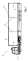
- the semitrailer 1 shown schematically in Fig. 1 consists of a Tractor 2 and a semi-trailer 3.
- the semi-trailer 3 is as Sliding roof formed in which a cargo area 4 in the corners arranged vertical post 5, the horizontal, in the direction of travel extending side member 6 and not visible in the side cross member support, wherein between the two posts 5 two stanchions 7 arranged are that connect the cargo area 4 with the side rails 6 and these vertically support.
- Sideboards hang from the side rails 6 side down, and a roof tarpaulin is displaceable between the two longitudinal members 6 arranged.
- To improve the load capacity of the loading platform is at Racks of sliding covers, as shown in Fig. 1, usually at least the stanchion 7 is designed so that it is out of its anchorage can be solved, sometimes the side members 6 and the post 5 solvable.
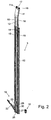
- FIG. 2 is the perspective view a preferred embodiment of a stanchion arrangement with a Runge 7 according to the invention and a fastening member 10, present as Runge shoe trained, the outside of the bed 4 of the Sliding roof 3 set, for example, is screwed, shown.
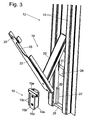
- the fastening member 10 consists of a U-shaped bent metal part 10a and a T-shaped metal part 10b, wherein in the vertically extending Section of the T-shaped metal part 10b and in the base of the U-shaped Metal part 10a aligned holes 10c are formed, can be passed through the fastening bolts to the Fix attachment member 10 in the cargo area 4.
- the one with the Holes 10c provided portion of the T-shaped metal part 10b has a distance to the base of the U-shaped metal part 10 a, but fills the Distance between the two legs of the U-shaped metal part 10 a and prevents them from bending under load.
- the head 10e of the T-shaped metal part 10b is as a square solid material configured and in recesses of the corners of the legs of the U-shaped Inserted metal part 10a and projects beyond the legs of the U-shaped on both sides Metal part 10a. Close up the two metal parts 10a, 10b flush and define a horizontal bearing surface, while the vertical Section of the T-shaped metal part 10b down over the U-shaped Metal part 10a protrudes and defines a nose 10d. Together they form the Metal parts 10a and 10b a stable and torsion-resistant fastening member 10, which can transfer forces well in all directions. Especially on the Head 10e acting vertical forces are on both metal parts 10a, 10b in the frame (not shown) of the loading area 4 of the sliding roof 3 derived.
- the stanchion 7 consists of an upper stake part 11 and a lower one Rung part 12, which are formed such that they are relative to each other displaced and thus the stanchions 7 in the production variable in height are.
- the upper Rungenteil 11 has a hole 13, in the one Lock bolt 14 of the lower Rungenteils 12 engages and thus the height of the Runge 7 determines. Through the hole 13 and the locking bolt 14 it is possible, from standardized upper stake part 11 and lower stake part 12 stanchions to produce 7 different heights without this in each case other parts are needed.
- the lower Rungenteil 12 has in the region of its connection with the upper Rung part 11 a flat shape, the two rectangular projections 15th has, in the respective corresponding elevations 16 of the upper Rurgiteils 11 intervene. As a result, a good transmission of forces and moments of the lower Rurgiteils 12 ensures the upper stake part 11.
- the connection of the two rungs parts 11, 12 is the back of the Projections 15 with a cover plate 12 a, which at the lower stake part 12 is screwed tight, closed.
- the upper rungs portion 11 in its upper portion a T-shaped extension 17, in whose Ends two double rollers 18 are mounted, which in a career of the Longitudinal member 6 intervene.
- This can be unlocked Runge 7 through the Rolls of rollers 18 these are moved along the longitudinal member 6.
- One Supporting portion 11a of the upper Rurgiteils 11 is a flat horizontal support trained and destined, after raising the stanchion 7 in Appendix to get against a lower flat side of the associated side member 6, whereby the rollers 18 are relieved at locked Runge 7 and also one possibly existing deflection of the longitudinal member 6 counteracted becomes.
- the stanchion 7 with its lower portion on the Attachment member 10 is raised and locked so that the forces be introduced vertically into the Runge 7 and also lateral or vertical play is avoided.
- the intermediate lever 20 is on the one hand at the bottom Rung part between the two rectangular projections 15 in the area a fixing unit 21a in a hinge 21 and at the other end the main lever 22 via a hinge 23, wherein the short lever arm 22a of the main lever 22 end a claw portion 24 has, and the long Lever 22b of the main lever 22 has a handle recess 25 at its the Joint 23 facing away from the end.
- the claw part 24 is at a solid support member 29 set.
- the stanchion 3 has at its lower Rungenteil 12th a crosspiece 26, which is the area between the two projections 15 connects with each other and at the same time opposite the front sides of the Projections 15 springs back.
- the crossbar 26 limits a Recess 30 in the foot region of the lower Rungenteils 12 down.
- the Recess is dimensioned so that the stanchion 7 there over the fastener 10 can be pushed.
- Vertical and in the region of the projections 15 are further arranged on both sides of the transverse web 26 upstanding struts 27, the opposite the bridge 26 jump back another piece.
- an abutment 28 in the form of a block made of metal, which is centered between the two projections 15 on the welded lower rung portion 12 or other suitable manner is attached.
- the anvil 28 is about as wide as the support member 29 or the attachment member 10. Between the anvil 28 and the Projections 15 each have a gap 31 is provided.
- the distance between Cross bar 26 and thrust bearing 28 corresponds approximately to the common height of Support member 29 and attachment member 10th
- the support member 29 is by welding or preferably by Screw firmly connected to the main lever 22. At the same time is in the Support member 28 and the bearing of the joint 23 is provided. Alternatively could the articulation with the joint 23 also on another part of Main lever 22 may be provided, the outside of the support member 29th is arranged, for example in one area (with locked Runge 7) above the anvil 28.
- the support member 29 has the top of the Attachment member 10 and the underside of the thrust bearing 28 facing Bounding surfaces which are adapted to this in shape, present So flat boundary surfaces. It is possible that the lower Rieuxteil 12th To round off facing corners of the support member 29. For attachment of the Klauenteils 24, the support member 29 is slightly less thick than that for Available depth of the recess 30 configured.
- the claw part 24 is intended behind the head 10e of the T-shaped Metal part 10b to grab and with its end-side turn first to hook the main lever 22 in the attachment member 10.
- the car 17th mounted in the side member 6 and the recess 30 of the stanchion 7 via the fastening member 10 passed over in such a way that the transverse web 26 itself behind and below the downwardly projecting nose 10d of the T-shaped Metal part 10 b is located and the struts 27, the U-shaped metal part 10 a laterally frame.
- the knee lever assembly 19 is raised or pivoted upwards. This can be done by hand, in In the present embodiment, this is a leaf spring 32nd provided on the intermediate lever 22 and on the lower Rurgiteil 12th is fixed and spreads them apart.
- the claw part 24 is in the upper slot of the attachment member 10, of the parts 10 a, 10 b is introduced, as shown in Fig. 4 and Fig. 8 is introduced. Due to the toggle lever assembly 19 is then by pressing the Main lever 22, for example in the area of the handle unit 25, toward the body of the lower Rungenteils 12 Runge 7 raised. The forces for the raising of the stanchion 7 are during the operation of the Lever assembly 19 via the two joints 21, 23 of the Attachment member 10 on the stanchion 7 and the stanchion 7 on the Transposed longitudinal member 6.
- the support element 29 is integrally formed and a slightly narrower lower section and a slightly wider upper section Section, wherein the upper portion at the same time a bearing for the Joint 23 has. It is possible, the joint 23 also elsewhere to provide and the support member 29 as a part of uniform thickness train. It is also possible to use the two sections as adjacent To design parts of a multi-part support element, whereby the production large quantities becomes more economical, even if this causes the Increase tolerances of the support element. Due to the greater width of the Upper section of the support element will be good for the reliable Supporting the stanchion 7 advantageous overlap with the anvil 28th achieved.
- the main lever 22 has in the end part of its long lever arm 22 b in approximately rectangular cutout 33, to which a lowered portion 34th adjoined.
- a (not shown) snap the lowered portion 34 and holds the Main lever 22 releasably attached to the lower Rungenteil 12.
- the snap device has a Release button, which is moved up to release the latch can be.
- the punching 33 is advantageous in the vicinity of the Grip recess 25 arranged that the thumb of an operator Solenoid button can operate while the hand, the handle recess 25th be upheld. Since the lever assembly 19 in the locked state of Runge. 7 force-free, the snap device can absorb small forces be designed so that the one-handed operation of the lever assembly 19th is possible.
- Fig. 12 and 13 it can be seen that the foot portion of the lower Rungenteils 12 of the stanchion 7 at least in a region surrounding the recess 30, is additionally reinforced, although the profile in the form of a double C defining projections 15 already to the lower end of the lower Rung part 12 continued uninterrupted and thus a favorable Transmission of vertical forces allows.
- the crosspiece 26 and the struts 27 are formed as a common group, either by welding or as a common casting, and in the foot area the stanchion 7 are welded. In this case, the transverse web 26 reaches a thickness, which accounts for more than half the depth of the projections 15.
- angle profiles 35 are welded, which extends into the area of Counter bearing 28 rich and thus the projections 15 in addition stiffen.
- the end of the free leg of the angle section 35 is in a short decency to the inside of the outer walls 15a of the Projections 15 arranged. It is possible to pick up this distance and the back of the projections 15 to close completely.
- the angle profiles 35 may also be welded to the struts 27.
- a Assembly of cross bar 26, struts 27 and angle sections 35, possibly even with the counter bearing 28, be made of one piece and in the foot of the Runge 7 are welded.
- the invention is based on a stanchion with a support element 28 above been described, which has a flat bottom for resting on the plane Upper side of the fastening member 10, and in which a claw part 24th penetrates into a slot of the fastening member 10.
- a support element 28 above has a flat bottom for resting on the plane Upper side of the fastening member 10, and in which a claw part 24th penetrates into a slot of the fastening member 10.
- Support member one to the contour of the upper side of the fastening member 10th Complementary stage, for example, when the attachment member 10 has an upwardly projecting nose similar to the nose 10d, wherein the grading in the corresponding, e.g. as a stemming member trained support member also recognized the main lever low can be.
Landscapes
- Engineering & Computer Science (AREA)
- Combustion & Propulsion (AREA)
- Transportation (AREA)
- Mechanical Engineering (AREA)
- Chemical & Material Sciences (AREA)
- Handcart (AREA)
- Refuge Islands, Traffic Blockers, Or Guard Fence (AREA)
- Body Structure For Vehicles (AREA)
- Fittings On The Vehicle Exterior For Carrying Loads, And Devices For Holding Or Mounting Articles (AREA)
- Saccharide Compounds (AREA)
- Steroid Compounds (AREA)
- Emergency Lowering Means (AREA)
- Seats For Vehicles (AREA)
- Tents Or Canopies (AREA)
Abstract
Description
Die Erfindung betrifft eine Runge nach dem Oberbegriff des Anspruchs 1.The invention relates to a stanchion according to the preamble of claim 1.
Rungen werden in der Praxis zum Abstützen von horizontalen Trägem von Planenaufbauten wie zum Beispiel Schiebeverdecken vorgesehen. Ein solcher Planenaufbau kann für Aufbauten von Lastkraftfahrzeugpritschen oder von Sattelaufliegern ausgestaltet sein, aber auch bei Containern oder Eisenbahnwaggons. Bei Schiebeverdecken sind, um diese schnell beladen oder entladen zu können, die von den Trägem herabhängenden Seitenplanen zusammenschiebbar, und auch die zwischen den Längsträgern verlaufende Dachplane kann mittels verfahrbarer Spriegel, an denen die Dachplane festgelegt ist, zusammengeschoben werden. Um den Zugang zum Laderaum weiter zu verbessern, sind die Verdeckgestelle der Schiebeverdecke leicht demontierbar ausgestaltet. Insbesondere die Mittelrungen sollen schnell entfernt werden können, häufig aber auch die Eckrungen, die auch als Pfosten bezeichnet werden, wobei in diesem zweiten Fall auch die Träger abgebaut werden müssen, während diese bei Lösen nur der Mittelrungen bei unbewegtem Schiebeverdeck von den Pfosten ausreichend abgestützt werden. Andere Planenaufbauten stützten ein Chassisdach ab, das zum Beispiel mit geringem Gewicht aus einer auf den Längsträgern vernieteten Kunststofffolie ausgebildet ist, so daß die Verschiebung nur der Seitenplane vorgesehen ist.Stanchions are used in practice for supporting horizontal girders Tarpaulins such as sliding covers provided. Such a Tarpaulin construction can be used for constructions of truck beds or of Semitrailers be designed, but also in containers or Railcars. With sliding covers are to load these quickly or to be able to unload, the side tarpaulins hanging from the carriers zusammenschiebbar, and also running between the side rails Roof tarpaulin can by means of movable bow, to which the roof tarpaulin is fixed, pushed together. To access the cargo space To further improve, the top frames of the sliding covers are lightweight dismountable designed. In particular, the Mittelrungen should be fast can be removed, but often also the corner stanchions, which also as a post be referred to, in this second case, the carrier degraded while they are solving only the middle stalls at unmoved sliding roof by the posts sufficiently supported. Other tarpaulins supported a chassis roof, for example with low weight from a riveted on the side rails plastic film is formed so that the displacement of only the side tarpaulin is provided.
Aus der Praxis sind eine Reihe von Rungenanordnungen bekannt, wo jeweils eine Runge an einem entsprechenden Befestigungsglied, das auch als Rungenschuh bezeichnet wird, mittels schnell lösbarem Verschluss verriegelbar sind, wobei der Rungenschuh in der Regel an einem tragenden Aussenteil der Ladefläche des Schiebeverdecks, beispielsweise einem Metallrahmen, der Holzlatten abstützt, festgelegt ist, beispielsweise durch Verschrauben oder durch Verschweissen. From practice a number of stanchion arrangements are known, where respectively a stanchion on a corresponding attachment member, which also as Runge shoe is called, lockable by means of quick release closure are, with the Runge shoe usually on a supporting outer part of the Loading surface of the sliding roof, such as a metal frame, the Wooden slats supported, is fixed, for example by screwing or by welding.
Eine erste aus der Praxis bekannte Ausführungsform einer verriegelbaren Mittelrunge weist eine Hebelanordnung mit einem Zwischenhebel und einem Haupthebel auf, wobei der Zwischenhebel mit einem ersten Gelenk an der Runge und über ein zweites Gelenk an dem Haupthebel angelenkt ist und der Haupthebel an dem langen Hebelarm einen Betätigungsgriff und an dem kurzen Hebelarm eine Ausbildung als Stemmglied aufweist. Zum Verriegeln der Runge wird das Stemmglied hinter eine nach oben vorspringende Nase des Rungenschuhs angesetzt und durch Betätigen des Haupthebels die Runge nach oben von dem Rungenschuh über die beiden Hebel weggedrückt, bis die Hebelanordnung verriegelt wird. Bei dieser Ausführungsform wird die gesamte Last der Runge und des Längsträgers und alle auch während der Fahrt auf die Runge einwirkenden Kräfte über die beiden Gelenke auf den Rungenschuh übertragen, wodurch die Gelenke extrem beansprucht werden und die Runge nur eine begrenzte Standzeit aufweist. Darüber hinaus weist diese Ausführungsform keine Fixierung der Runge in Richtung der Längsträger auf.A first known from practice embodiment of a lockable Mittelrunge has a lever assembly with an intermediate lever and a Main lever, wherein the intermediate lever with a first joint on the Runge and a second joint is hinged to the main lever and the Main lever on the long lever arm an operating handle and on the short lever arm has a training as a caulking. To lock the Runge becomes the stemming member behind an upwardly projecting nose of the Runge shoe set and by pressing the main lever, the Runge pushed upwards from the stanchion shoe over the two levers until the Lever assembly is locked. In this embodiment, the entire Load of the stanchion and the longitudinal member and all while driving on the Runge acting forces on the two joints on the Runge shoe transmitted, whereby the joints are extremely stressed and the stanchion has only a limited life. In addition, this one has Embodiment no fixation of the stanchion in the direction of the side members.
Eine zweite aus der Praxis bekannte Ausführungsform einer verriegelbaren Mittelrunge weist einen Steigbügelartigen ersten Hebel auf, der in ein U-Profil eines Rungenlagers eingesetzt wird, und einen zweiten Hebel, der an dem Korpus der Runge angelenkt ist und der über einen Zwischenhebel mit einem in dem Korpus der Runge axial verlagerbaren Riegelkeil gekoppelt ist, wobei das Rungenlager eine Tasche für die Aufnahme des Riegelkeils aufweist. Zunächst wird die unter einem Winkel zum ersten Hebel stehende Runge in Richtung auf das Rungenlager verschwenkt und hierbei angehoben, wobei die Vertrikalkräfte über den ersten Hebel und dessen Anlenkung in die Runge eingeleitet werden. Der Riegelkeil wird dann durch Betätigung des zweiten Hebels in die Tasche des Rungenlagers abgesenkt und hierdurch die labil um das Gelenk mit dem ersten Hebel kippende Runge verriegelt. Der Riegelkeil kann nur bei Versagen des ersten Hebels und seiner dynamisch stark beanspruchten Gelenk an der Runge vertikale Belastungen der Runge in die Fangtasche einleiten, dies aber nur über den zweiten Hebel und seine Anlenkung, der hierzu nicht ausgelegt ist. Ferner stellt der verlagerbare Riegelkeil selbst einen weiteres verschleissanfälliges Teil dar. Die bekannte Rungenanordnung ist jedoch schwierig in der Handhabung, da sie manuell in die angehobene Position verlagert werden muss.A second known from practice embodiment of a lockable Mittelrunge has a stirrup-like first lever, which in a U-profile a stanchion bearing is used, and a second lever which on the Body of the stanchion is hinged and the over an intermediate lever with a in the body of the Runge axially displaceable locking wedge is coupled, wherein the Rungenlager has a pocket for receiving the locking wedge. First becomes the Runge at an angle to the first lever in the direction of the stanchions pivoted and thereby raised, the forces of the contract be introduced via the first lever and its articulation in the stanchion. The locking wedge is then by pressing the second lever in the bag lowered the stanchion bearing and thereby the unstable around the joint with the first lever tilting Runge locked. The locking wedge can only in case of failure the first lever and its dynamically stressed joint on the Runge initiate vertical loads of the stanchion into the catch pocket, but this only on the second lever and its linkage, which is not designed for this purpose is. Furthermore, the displaceable locking wedge itself is another wear-prone part dar. The known Rungenanordnung is however difficult to handle, as they are manually in the raised position must be relocated.
Eine dritte aus der Praxis bekannte Ausführungsform einer verriegelbaren Mittelrunge weist einen an dem Korpus der Runge angelenkten Hebel auf, dessen einer Hebelarm einen Griff aufweist und dessen anderer Hebelarm in ein U-förmiges Rungenlager einführbar ist, wobei die Runge durch Drücken des Hebels mit dem Griff auf den Korpus der Runge angehoben wird. Auch hier werden die vertikalen Kräfte von dem Rungenlager über den Hebel in die Runge eingeleitet. A third known from practice embodiment of a lockable Middle stanchion has a lever articulated on the body of the stanchion, whose one lever arm has a handle and whose other lever arm in a U-shaped stanchions bearing is insertable, wherein the Runge by pressing the Levers with the handle on the body of the stanchion is raised. Here too The vertical forces are transferred from the stanchion via the lever into the stanchion Runge initiated.
DE-A-200 00 002 zeigt eine der vorstehend beschriebenen dritten aus der Praxis bekannten entsprechende Runge. Die Runge ist in ihrem unteren Bereich über ein Gelenk mit einem als doppelarmiger Hebel ausgebildeten Schwenkglied verbunden, an dessen einem Ende ein als Rundstab ausgebildeter Endbereich in eine U-förmige Lagerhalbschale eines Befestigungsgliedes eingesetzt wird. Das Schwenkglied leitet die Gewichtskräfte über das Gelenk in die Runge ein. Zum Ein- und Aushängen der Runge ist an dem den Rundstab abgekehrten anderen Ende des Schwenkgliedes mittels einer Achse ein Ende eines oberen Kniehebelgliedes eines Kniehebels verbunden, wobei das andere Ende des oberen Kniehebelglieds über eine weitere Achse mit einem mittleren Bereich eines unteren Kniehebelglieds verbunden ist. Das untere Kniehebelglied ist als doppelarmiger Hebel ausgebildet, dessen unterer Hebelarm über eine Anlenkachse in einem Langloch mit einem Verriegelungskeil verbunden ist. Der Verriegelungskeil ist dazu bestimmt, in eine Keiltasche des Befestigungsgliedes einzudringen, während der obere Hebelarm als Betätigungshebel ausgebildet ist. Der Betätigungshebel wird durch eine Schnappeinrichtung im geschlossenen Zustand gehalten. Der Verriegelungskeil wird durch eine Feder in die Keiltasche gedrückt.DE-A-200 00 002 shows one of the above-described third of Practice known corresponding Runge. The stanchion is in its lower Range over a joint with a designed as a double-armed lever Pivoting member connected, at one end of a round rod trained end portion in a U-shaped bearing half-shell of a Attachment member is used. The pivot member directs the Weight forces over the joint into the stanchion. For mounting and unmounting the stanchion is at the other end of the round bar turned away Swivel member by means of an axis one end of an upper toggle link a knee lever connected, the other end of the upper Toggle link on another axis with a central region of a lower toggle link is connected. The lower toggle link is as formed double-armed lever whose lower lever arm over a Anlenkachse is connected in a slot with a locking wedge. Of the Locking wedge is intended to be in a wedge pocket of the attachment member penetrate while the upper lever arm formed as an actuating lever is. The operating lever is by a snap device in kept closed state. The locking wedge is by a spring pressed into the key pocket.
Es ist die Aufgabe der Erfindung, eine Runge nach dem Oberbegriff des Anspruchs 1 zu schaffen, die zuverlässig verriegelbar ist und eine verbesserte Standzeit aufweist.It is the object of the invention to provide a stanchion according to the preamble of To provide claim 1, which is reliably lockable and improved Life has.
Diese Aufgabe wird bei der eingangs erwähnten Runge erfindungsgemäß mit den kennzeichnenden Merkmalen des Anspruchs 1 gelöst. This object is according to the invention in the aforementioned Runge the characterizing features of claim 1 solved.
Die erfindungsgemäße Runge schafft damit eine zuverlässigen Kraftfluss von dem Befestigungsglied zu dem Korpus der Runge. Insbesondere wenn das Gegenlager fest an dem Korpus der Runge angeordnet ist werden die vertikalen Kräfte zuverlässig übertragen. Die Standzeit einer solchen Runge ist, weil anfällige gelenkige Teile nicht nach der Verriegelung und insbesondere während der Fahrt beansprucht werden, deutlich verbessert.The Runge invention thus creates a reliable power flow of the attachment member to the body of Runge. Especially if that Counter bearing is fixed to the body of the stanchion are the transmit vertical forces reliably. The lifetime of such a stanchion is, because prone hinged parts are not after locking and in particular claimed while driving, significantly improved.
Die Übertragung der vertikalen Kräfte von dem Befestigungsglied auf die Runge ist besonders vorteilhaft, wenn die Berührungsebene Befestigungsglied und Stützelement und auch die Berührungsebene Stützelement und Gegenlager horizontal und damit senkrecht zu der Hauptwirkrichtung der übertragenen Kräfte ausgebildet ist oder zumindest horizontale Abschnitte aufweist. Zugleich ermöglicht diese bevorzugte Art der formschlüssigen Anordnung eine einfache Fertigung und eine einfach zu berechnende Auslegung der Teilestärken. Alternativ kann aber auch vorgesehen werden, dass die Begrenzungen des Stützelements, jeweils angepasst an die Kontur der beiden benachbarten Teile, in mehreren Ebenen liegt, z.B. in der Art mit mehreren Abstufungen, um das Einführen zu erleichtern, oder aber mit einer zur Horizontalen geneigten Ebene, z.B. wenn das Stützelement eine Keilform aufweist. Insbesondere kann die untere Begrenzung des Stützelements in ihrer Ausgestaltung an bekannte Rungenschuhe angepasst sein, so dass jederzeit unbrauchbar gewordene Rungen aus dem Stand der Technik ohne Umbau des Befestigungsgliedes durch eine erfindungsgemäße Runge ersetzt werden können oder bestehende Rungen durch Nachrüsten eines Stützelements und/oder eines Gegenlagers erfindungsgemäß ausgeführt werden.The transfer of vertical forces from the attachment member to the Runge is particularly advantageous when the touch plane attachment member and support member and also the contact plane support member and Counter bearing horizontal and thus perpendicular to the main direction of the transmitted forces is formed or at least horizontal sections having. At the same time allows this preferred type of positive Arrangement a simple manufacture and an easy to calculate Design of the parts strengths. Alternatively, however, it can also be provided that the boundaries of the support element, each adapted to the contour the two adjacent parts, in several levels, e.g. in style with several gradations to facilitate insertion, or with one plane inclined to the horizontal, e.g. when the support element is a wedge shape having. In particular, the lower boundary of the support element in its Design adapted to known Runge shoes, so that at any time become obsolete stanchions from the prior art without modification of the Fastener be replaced by a Runge invention can or existing stanchions by retrofitting a support element and / or an abutment are carried out according to the invention.
Grundsätzlich kann das Stützelement ein von Runge oder Befestigungsglied ablösbares Teil sein, das beim Entriegeln der Runge separat aufbewahrt wird und beim Verriegeln der Runge zwischen Befestigungsglied und dem mit der Runge fest verbundenen Gegenlager eingesetzt wird. In diesem Fall ist das Stützelement vorzugsweise mit einem eigenen Griff zum Herausziehen ausgestaltet und kann ferner einen Kragenabschnitt aufweisen, mit dem es in Einsetzrichtung einen Endanschlag definiert und bei Bedarf eine Begrenzung für einen schwenkbar an der Runge angeordneten Hebel aufweist. Ferner kann das ablösbare Stützelement noch eine Bohrung aufweisen, die zur Aufnahme eines Sicherungsstiftes vorgesehen ist, der zum Beispiel die Runge horizontal durchsetzt, wobei dann bei entriegelter Runge das ablösbare Stützelement mit diesem Sicherungsstift wieder gehaltert werden könnte. Zweckmässigerweise würde ein solches ablösbares so bemessen sein, dass es auch in Querrichtung die Runge an dem Befestigungsglied festlegt; eine mögliche Ausgestaltung kann in einer das Befestigungsglied umrahmenden und von dem Fussbereich der Runge umrahmten Form gewählt sein.Basically, the support element of a Runge or attachment member detachable part, which is stored separately when unlocking the stanchion and when locking the stanchion between the attachment member and the with the Runge firmly connected counter bearing is used. In this case that is Support element preferably with its own handle for pulling out configured and may further comprise a collar portion with which it is in Insertion defined an end stop and if necessary a limit for a pivotally arranged on the stanchion lever. Furthermore, can the detachable support element still have a hole for receiving a locking pin is provided, for example, the stanchion horizontal interspersed, in which case with unlocked Runge the removable support element with this locking pin could be held again. Conveniently, such a detachable would be such that it is also transversal fixing the stanchion to the attachment member; a possible embodiment can in a framing the attachment member and the foot area the stave framed form should be chosen.
Ebenso kann das Stützelement an dem Befestigungsglied oder an einem mit dem Befestigungsglied fest verbundenen Teil, beispielsweise der Ladefläche, an der das Befestigungsglied festgelegt ist, z.B. schwenkbar angeordnet sein, so dass beim Entriegeln der Runge das Stützelement nicht verloren geht.Likewise, the support member on the attachment member or at one with the fastening member firmly connected part, such as the loading area, where the attachment member is fixed, e.g. be arranged pivotally, so that when unlocking the stake the support element is not lost.
Besonders bevorzugt ist jedoch das Vorsehen des Stützelements an einem Teil der Runge, wobei das Teil oder das Stützelement zweckmässigerweise schwenkbar an der Runge gelagert ist, so dass das Stützelement auch bei entriegelter Runge nicht verlorengeht.However, particularly preferred is the provision of the support element on a part the Runge, wherein the part or the support element conveniently is pivotally mounted on the stanchion, so that the support element also at unlocked stanchion is not lost.
Es ist insbesondere möglich, das Stützelement mehrteilig auszuführen und hierbei verschiedene Anordnungen zu kombinieren, z.B. ein ablösbares erstes Stützelement und ein an der Runge vorgesehenes zweites Stützelement, die gemeinsam die vertikalen Kräfte von der Runge in das Befestigungsglied übertragen.It is particularly possible to carry out the support element in several parts and to combine different arrangements, e.g. a removable first Support member and provided on the stanchion second support member, the Together, the vertical forces from the stanchion into the attachment member transfer.
Die erfindungsgemässe Runge umfasst eine Hebelanordnung, etwa eine Kniehebelanordnung, die vorzugsweise wenigstens einen Hebel an der Runge lagert, mit dem die Runge angehoben werden kann, so dass ein Anheben von Hand nicht erforderlich ist. Eine solche Hebelanordnung kann sowohl einen direkt an den Korpus der Runge gekoppelten Hebel als auch mehrere Hebel umfassen. Zweckmässigerweise wird ein Ende eines der Hebel für das Anheben der Runge gegen das Befestigungsglied abstützbar sein und ein entsprechendes, z.B. als Stemmglied ausgebildetes Ende aufweisen. Da die Gelenke und Lager der Hebel bei der erfindungsgemässen Runge in ihrem verriegelten Zustand nicht mehr oder deutlich weniger beansprucht werden, stellen die Gelenke der Runge nicht mehr das kritische Bauteil der Runge dar. Es ist vorzugsweise vorgesehen, dass die Hebelanordnung nur zum Anheben bzw. langsamen Absenken der mit dem Befestigungsglied in Eingriff steht und hiernach jeweils ausgehängt werden kann.The stanchion according to the invention comprises a lever arrangement, such as a toggle lever assembly, preferably at least one lever on the stanchion stores, with which the stanchion can be raised, so that a raising of Hand is not required. Such a lever arrangement can both a directly to the body of the stanchion coupled lever as well as several levers include. Conveniently, an end of one of the levers for the Lift the stanchion be supportable against the fastening member and a corresponding, e.g. Having trained as a caulking end. Because the Joints and bearings of the lever in the invention Runge in her locked state no longer or significantly less stressed, The joints of the stanchion are no longer the critical component of the stanchion. It is preferably provided that the lever arrangement only for lifting or slowly lowering the engaged with the fastening member and hereafter can be posted.
Eine besonders vorteilhafte Weiterbildung der erfindungsgemässen Runge, die mit einer Hebelanordnung versehen ist, besteht im Anordnen des Stützelements an einem der Hebel der Hebelanordnung. So wird vorteilhaft die Betätigung der Hebelanordnung zur Verriegeln mit dem Einsetzen bzw. zum Entriegeln mit dem Herausnehmen des Stützelements kombiniert, ohne dass hierzu zusätzliche Handhabungen erforderlich werden. Sobald das Stützelement herausgezogen ist - was regelmässig nur bei stehendem Fahrzeug vorkommt -, übernimmt die Hebelanordnung die Last der Runge, bis diese abgesenkt ist. Umgekehrt wird die Hebelanordnung mit dem Verriegeln zugleich entlastet. Das Stützelement kann hierbei sowohl von der äusseren Seite als auch von der inneren Seite der Runge eingesetzt werden.A particularly advantageous development of the invention Runge, the is provided with a lever arrangement, consists in arranging the Support member on one of the lever of the lever assembly. So will the advantageous Actuation of the lever assembly for locking with the insertion or to Unlocking combined with the removal of the support element without this additional handling will be required. As soon as that Support element is pulled out - which regularly only when standing Vehicle occurs, the lever assembly takes over the load of Runge until this is lowered. Conversely, the lever assembly with the lock relieved at the same time. The support element can in this case both from the outer Side as well as from the inner side of the stanchion.
Vorzugsweise weist die Runge in ihrem Fußbereich unterhalb einer für das Hindurchtreten des Befestigungsglieds vorgesehenen Aussparung in ihrem Korpus einen Quersteg auf, der bei verriegelter Runge hinter eine nach unten vorspringende Nase des Befestigungsglieds angehoben wird und damit eine Sicherung in Richtung weg von der Ladefläche definiert, während der Rahmen der Ladefläche einen Anschlag für den Fußbereich der Runge definiert. Ferner sind vorzugsweise von dem Quersteg emporstehende Streben vorgesehen, die im verriegelten Zustand der Runge so weit angehoben sind, dass sie hinter ein seitlich überstehendes Teil des Befestigungsglieds reichen und damit die Sicherung durch den Quersteg ergänzen. Der Abstand der Streben ist vorteilhaft so bemessen, dass sie das Befestigungsglied ohne oder mit geringem Spiel umrahmen und damit auch ein Schlagen der Runge in ihrer Querrichtung parallel zu dem Quersteg verhindern. Die Streben sind dabei vorteilhaft so bemessen, dass sie bei verriegelter Runge etwas nach oben über das seitlich überstehende Teil des Befestigungsglieds vorstehen. Vorzugsweise ist vorgesehen, dass die Streben dann ferner das Stützelement seitlich abstützen, wenn dieses so dick ausgebildet ist, dass es zwischen die in der Runge in einem hinteren Bereich angeordneten Streben reicht. Alternativ kann vorgesehen werden, dass das Stützelement nicht bis in den Bereich der Streben reicht, sondern nur auf einem vorderen Abschnitt des Befestigungsglieds aufliegt.Preferably, the stanchion has in its foot area below one for the Passing through the fastening member provided recess in her Body on a crossbar on, with locked Runge behind a down projecting nose of the attachment member is raised and thus a Fuse defined in the direction away from the cargo bed while the frame the loading area defined a stop for the foot of the stanchion. Further are preferably provided by the crosspiece upstanding struts, the in the locked state of the stanchion are raised so far that they are behind a extend laterally projecting part of the fastening member and thus the Complete securing with the crosspiece. The distance of the struts is Advantageously dimensioned so that they are the attachment member without or with frame little game and thus also a beating of the stakes in their Prevent transverse direction parallel to the crosspiece. The aspirations are there Advantageously dimensioned so that they slightly upwards with locked Runge protrude the laterally projecting part of the fastening member. Preferably is provided that the struts then also the support element laterally support, if this is so thick that it is between the in the Runge reaches in a rear area arranged struts. Alternatively, you can be provided that the support element is not up to the area of Striving is enough, but only on a front section of the Mounting member rests.
Vorzugsweise wird die Aussparung im Fussbereich der Runge von dem Gegenlager begrenzt, so dass das Stützelement klein und damit mit geringem Gewicht ausgebildet werden kann. Preferably, the recess in the foot region of the Runge of the Limiting abutment, so that the support element small and thus with low Weight can be formed.
Die erfindungsgemäße Runge kann vorteilhaft durch ihre Ausbildung mit einem doppel-C Profil, das über die Länge der Runge nicht unterbrochen ist und vorzugsweise im Fußbereich im Bereich der zentralen Aussparung Verstärkungen aufweist besonders gut vertikale Kräfte übertragen. Der geschlossene, nicht unterbrochene Rahmen im unteren Rungenteil ermöglicht daher eine hohe Belastung der Runge. Ferner definiert die Runge wenigstens in dem zentralen Abschnitt zwischen den beiden C-förmigen Auskragungen eine der Ladung zugekehrte Rückwand, in der auf einfache Weise mit Lochungen oder dgl. mit geringem Aufwand Aufnahmen für zum Beispiel einen zweiten horizontalen Boden zur mehrgeschossigen Beladung mit schlecht stapelbaren Gütern oder Befestigungsmittel für Ladeguttrennungen oder Ladegutsicherungen oder Gurte. Die gute Übertragung der Kräfte der erfindungsgemäßen Runge ermöglicht dies ohne vorzeitigen Ausfall der Runge und ohne dass hierfür gesonderte Tragmittel vorzusehen sind.The Runge invention can be advantageous by their training with a double-C profile that is uninterrupted over the length of the stanchion and preferably in the foot area in the region of the central recess Reinforcements has transferred very well vertical forces. Of the closed, not interrupted frame in the lower Runge part allows therefore a high burden of Runge. Furthermore, the stanchion defines at least in the central portion between the two C-shaped projections a charge-facing rear wall, in the simple way with Holes or the like. With little effort recordings for example a second horizontal floor for multi-storey loading with bad stackable goods or fasteners for cargo separations or Load securing or straps. The good transmission of the forces of Runge invention allows this without premature failure of the stanchion and without the need for separate support means are provided.
Eine erfindungsgemäße Rungenanordnung bzw. ein erfindungsgemäßer Planenaufbau zeichnen sich durch eine erfindungsgemäße Runge aus.An inventive stanchion arrangement or an inventive Tarpaulin structure are characterized by a Runge invention.
Weitere Vorteile und Merkmale der Erfindung ergeben sich aus der nachfolgenden Beschreibung sowie aus den abhängigen Ansprüchen.Further advantages and features of the invention will become apparent from the subsequent description and from the dependent claims.
Die Erfindung wird nachstehend anhand eines bevorzugten Ausführungsbeispiels einer erfindungsgemäßen Runge unter Bezugnahme auf die anliegenden Zeichnungen näher erläutert.
- Fig. 1
- zeigt eine schematische Seitenansicht eines als Sattelauflieger ausgebildeten Schiebeverdecks mit gestrichelt eingezeichneten erfindungsgemäßen Rungen.
- Fig. 2
- zeigt eine perspektivische Ansicht einer erfindungsgemäßen Runge vor dem Festlegen an der Ladepritsche.
- Fig. 3
- zeigt den unteren Bereich der Runge aus Fig. 2 vor dem Festlegen an der Ladepritsche und das an der Ladepritsche angeordnete Befestigungsglied.
- Fig.4
- zeigt den unteren Bereich der Runge aus Fig. 2 beim Verriegeln an der Ladepritsche.
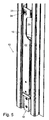
- Fig. 5
- zeigt den unteren Bereich der Runge aus Fig. 2 im verriegelten Zustand.
- Fig. 6
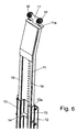
- zeigt den oberen Bereich der Runge aus Fig. 2.
- Fig. 7
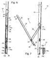
- zeigt eine teilweise geschnittene Seitenansicht des unteren Bereichs der Runge gemäß Fig. 3.
- Fig. 8
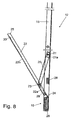
- zeigt eine teilweise geschnittene Seitenansicht des unteren Bereichs der Runge gemäß Fig. 4.
- Fig. 9
- zeigt eine teilweise geschnittenen Seitenansicht des unteren Bereichs der Runge gemäß Fig. 5.
- Fig. 10
- zeigt eine Draufsicht auf den unteren Bereich der Runge aus Fig. 2 im verriegelten Zustand.
- Fig. 11
- zeigt einen Längsschnitt durch den unteren Bereich der Runge aus Fig. 2 im verriegelten Zustand.
- Fig. 12
- zeigt eine Ansicht von unten auf den unteren Bereich der Runge aus Fig. 2 im unverriegelten Zustand.
- Fig. 13
- zeigt eine perspektivische Ansicht der Rückseite des unteren Bereichs der Runge aus Fig. 2.
- Fig. 1
- shows a schematic side view of a designed as a semi-trailer sliding roof with dashed lines invention stanchions.
- Fig. 2
- shows a perspective view of a Runge according to the invention before being fixed to the loading platform.
- Fig. 3
- shows the lower portion of the stanchion of Fig. 2 before being fixed to the loading platform and the fixing member arranged on the loading platform.
- Figure 4
- shows the lower portion of the stanchion of Fig. 2 when locking on the loading platform.
- Fig. 5
- shows the lower portion of the stanchion of Fig. 2 in the locked state.
- Fig. 6
- shows the upper portion of the stanchion of FIG. 2.
- Fig. 7
- shows a partially sectioned side view of the lower portion of the stanchion of FIG. 3rd
- Fig. 8
- shows a partially sectioned side view of the lower portion of the stanchion of FIG. 4th
- Fig. 9
- shows a partially sectioned side view of the lower portion of the stanchion of FIG. 5th
- Fig. 10
- shows a plan view of the lower portion of the stanchion of Fig. 2 in the locked state.
- Fig. 11
- shows a longitudinal section through the lower portion of the stanchion of Fig. 2 in the locked state.
- Fig. 12
- shows a bottom view of the lower portion of the stanchion of Fig. 2 in the unlocked state.
- Fig. 13
- shows a perspective view of the back of the lower portion of the stanchion of Fig. 2.
Der in Fig. 1 schematisch dargestellte Sattelzug 1 besteht aus einer
Zugmaschine 2 und einem Sattelauflieger 3. Der Sattelauflieger 3 ist als
Schiebeverdeck ausgebildet, bei dem eine Ladefläche 4 in den Ecken
angeordnete vertikale Posten 5 aufweist, die horizontale, in Fahrtrichtung
verlaufende Längsträger 6 und in der Seitenansicht nicht sichtbare Querträger
abstützen, wobei zwischen den beiden Pfosten 5 zwei Rungen 7 angeordnet
sind, die die Ladefläche 4 mit den Längsträgern 6 verbinden und diese vertikal
abstützen. Seitenplanen hängen von den Längsträgern 6 seitlich herab, und
eine Dachplane ist zwischen den beiden Längsträgern 6 verschiebbar
angeordnet. Um die Belastbarkeit der Ladepritsche zu verbessern ist bei
Gestellen von Schiebeverdecken, wie es in Fig. 1 dargestellt ist, in der Regel
wenigstens die Runge 7 derart ausgebildet, dass sie aus ihrer Verankerung
gelöst werden kann, manchmal sind auch die Längsträger 6 und die Pfosten 5
lösbar.The semitrailer 1 shown schematically in Fig. 1 consists of a
Insbesondere bei den Rungen 7 ist ein schnelles Spannen und Verriegeln
beziehungsweise Lösen erwünscht. In Fig. 2 ist die perspektivische Ansicht
eines bevorzugten Ausführungsbeispiels einer Rungenanordnung mit einer
erfindungsgemäßen Runge 7 und eines Befestigungsglieds 10, vorliegend als
Rungenschuh ausgebildet, das aussen an der Ladefläche 4 des
Schiebeverdecks 3 festgelegt, beispielsweise festgeschraubt ist, dargestellt.Especially with the stanchions 7 is a quick tightening and locking
or dissolution desired. In Fig. 2 is the perspective view
a preferred embodiment of a stanchion arrangement with a
Runge 7 according to the invention and a
Das Befestigungsglied 10 besteht aus einem U-förmig gebogenen Metallteil
10a und einem T-förmigen Metallteil 10b, wobei in dem vertikal verlaufenden
Abschnitt des T-förmigen Metallteils 10b und in der Basis des U-förmigen
Metallteils 10a miteinander ausgefluchtete Bohrungen 10c ausgebildet sind,
durch die Befestigungsbolzen hindurch geführt werden können, um das
Befestigungsglied 10 im Bereich der Ladefläche 4 festzulegen. Der mit den
Bohrungen 10c versehenen Abschnitt des T-förmigen Metallteils 10b weist
einen Abstand zu der Basis des U-förmigen Metallteils 10a auf, füllt aber den
Abstand zwischen den beiden Schenkeln des U-förmigen Metallteils 10a und
verhindert, dass diese sich bei Belastung verbiegen. Der sich horizontal
erstreckende Kopf 10e des T-förmigen Metallteils 10b ist als Vierkant-Vollmaterial
ausgestaltet und in Ausnehmungen der Ecken der Schenkel des U-förmigen
Metallteils 10a eingesetzt und überragt beidseitig die Schenkel des U-förmigen
Metallteils 10a. Nach oben schließen die beiden Metallteile 10a, 10b
bündig ab und definieren eine horizontale Auflagefläche, während der vertikale
Abschnitt de T-förmigen Metallteils 10b nach unten über das U-förmige
Metallteil 10a übersteht und eine Nase 10d definiert. Gemeinsam bilden die
Metallteile 10a und 10b ein stabiles und torsionsfestes Befestigungsglied 10,
das Kräfte in alle Richtungen gut übertragen kann. Insbesondere die auf den
Kopf 10e wirkenden vertikalen Kräfte werden über beide Metallteile 10a, 10b in
den (nicht dargestellten) Rahmen der Ladefläche 4 des Schiebeverdecks 3
abgeleitet.The
Die Runge 7 besteht aus einem oberen Rungenteil 11 und einem unteren
Rungenteil 12, die derart ausgeformt sind, dass sie relativ zueinander
verschiebbar und damit die Rungen 7 bei der Fertigung in der Höhe variabel
sind. Das obere Rungenteil 11 weist eine Lochung 13 auf, in die ein
Riegelbolzen 14 des unteren Rungenteils 12 eingreift und damit die Höhe der
Runge 7 festlegt. Durch die Lochung 13 und den Riegelbolzen 14 ist es
möglich, aus standardisiertem, oberem Rungenteil 11 und unterem Rungenteil
12 Rungen 7 unterschiedlicher Höhen herzustellen, ohne dass hierfür jeweils
andere Teile benötigt werden.The stanchion 7 consists of an
Das untere Rungenteil 12 weist im Bereich seiner Verbindung mit dem oberen
Rungenteil 11 eine flache Gestalt auf, die zwei rechteckige Auskragungen 15
aufweist, in die jeweils entsprechende Erhebungen 16 des oberen Rungenteils
11 eingreifen. Hierdurch ist eine gute Kräfte- und Momentenübertragung des
unteren Rungenteils 12 auf das obere Rungenteil 11 gewährleistet. Im Bereich
der Verbindung der beiden Rungenteile 11, 12 ist die Rückseite der
Auskragungen 15 mit einer Abdeckplatte 12a, die an dem unteren Rungenteil
12 festgeschraubt ist, verschlossen.The
Wie in Fig. 6 in größeren Einzelheiten zu erkennen, weist das obere Rungenteil
11 in seinem oberen Abschnitt einen T-förmigen Fortsatz 17 auf, in dessen
Enden zwei Doppelrollen 18 gelagert sind, die in eine Laufbahn des
Längsträgers 6 eingreifen. Damit kann bei entriegelter Runge 7 durch das
Rollen der Rollen 18 diese entlang des Längsträgers 6 verschoben werden. Ein
Stützbereich 11a des oberen Rungenteils 11 ist als flache horizontale Auflage
ausgebildet und dazu bestimmt, nach dem Anheben der Runge 7 in Anlage
gegen eine untere Flachseite des zugehörigen Längsträgers 6 zu gelangen,
wodurch bei verriegelter Runge 7 die Rollen 18 entlastet sind und ferner einer
möglicherweise vorhandene Durchbiegung des Längsträgers 6 entgegengewirkt
wird. As can be seen in greater detail in Fig. 6, the
Um eine wirksame vertikale Abstützung der Längsträger 6 zu erreichen ist es
erforderlich, dass die Runge 7 mit ihrem unteren Bereich an dem
Befestigungsglied 10 derart angehoben und verriegelt wird, dass die Kräfte
günstig vertikal in die Runge 7 eingeleitet werden und auch seitliches oder
vertikales Spiel vermieden wird. Hierzu weist die Runge 3, wie in Fig. 3 genauer
zu erkennen, eine Kniehebelanordnung 19 auf, mit einem Zwischenhebel 20
und einem Haupthebel 22. Der Zwischenhebel 20 ist einerseits an dem unteren
Rungenteil zwischen den beiden rechteckigen Auskragungen 15 im Bereich
einer Befestigungseinheit 21a in einem Gelenk 21 und mit anderen Ende an
dem Haupthebel 22 über ein Gelenk 23 gelagert, wobei der kurze Hebelarm
22a des Haupthebels 22 endseitig ein Klauenteil 24 aufweist, und der lange
Hebel 22b des Haupthebels 22 eine Handgriffausnehmung 25 an seinem dem
Gelenk 23 abgewandten Ende aufweist. Das Klauenteil 24 ist an einem
massiven Stützelement 29 festgelegt.In order to achieve effective vertical support of the
In ihrem unteren Bereich weist die Runge 3 an ihrem unteren Rungenteil 12
einen Quersteg 26 auf, der den Bereich zwischen den beiden Auskragungen 15
miteinander verbindet und zugleich gegenüber den Stirnseiten der
Auskragungen 15 zurückspringt. Zugleich begrenzt der Quersteg 26 eine
Aussparung 30 in dem Fußbereich des unteren Rungenteils 12 nach unten. Die
Aussparung ist so bemessen, dass die Runge 7 dort über das Befestiungsglied
10 geschoben werden kann. Vertikal und im Bereich der Auskragungen 15 sind
weiterhin beiderseits des Querstegs 26 aufragende Streben 27 angeordnet, die
gegenüber dem Steg 26 ein weiteres Stück zurückspringen.In its lower part, the
Oberhalb der Aussparung 30 ist ein Gegenlager 28 in der Gestalt eines Blocks
aus Metall, der zentrisch zwischen den beiden Auskragungen 15 an dem
unteren Rungenteil 12 angeschweißt oder in anderer geeigneter Weise
befestigt ist. Das Gegenlager 28 ist etwa so breit wie das Stützelement 29 oder
das Befestigungsglied 10. Zwischen dem Gegenlager 28 und den
Auskragungen 15 ist jeweils ein Spalt 31 vorgesehen. Der Abstand zwischen
Quersteg 26 und Gegenlager 28 entspricht in etwa der gemeinsamen Höhe von
Stützelements 29 und Befestigungsglied 10.Above the
Das Stützelement 29 ist durch Verschweißen oder vorzugsweise durch
Verschrauben fest mit dem Haupthebel 22 verbunden. Zugleich ist in dem
Stützelement 28 auch das Lager des Gelenks 23 vorgesehen. Alternativ könnte
die Anlenkung mit dem Gelenk 23 auch an einem weiteren Teil des
Haupthebels 22 vorgesehen sein, das außerhalb des Stützelements 29
angeordnet ist, beispielsweise in einem Bereich (bei verriegelter Runge 7)
oberhalb des Gegenlagers 28. Das Stützelement 29 weist der Oberseite des
Befestigungsglied 10 bzw. der Unterseite des Gegenlagers 28 zugekehrte
Begrenzungsflächen auf, die diesen in ihrer Form angepaßt sind, vorliegend
also flache Begrenzungsflächen. Es ist möglich, die dem unteren Rungenteil 12
zugekehrten Ecken des Stützelements 29 abzurunden. Zur Befestigung des
Klauenteils 24 ist das Stützelement 29 etwas weniger dick als die zur
Verfügung stehende Tiefe der Aussparung 30 ausgestaltet.The
Ausgehend von einer geöffneten Stellung der Runge 7, wie in Fig. 3 und Fig. 7
dargestellt, ist das Klauenteil 24 dazu bestimmt, hinter den Kopf 10e des T-förmigen
Metallteils 10b zu greifen und mit seiner endseitigen Abbiegung
zunächst den Haupthebel 22 in dem Befestigungsglied 10 zu verhaken.Starting from an open position of the stanchion 7, as in FIG. 3 and FIG. 7
shown, the
Zum Einhängen der Runge 7 wird, soweit noch nicht geschehen, der Wagen 17
in dem Längsträger 6 eingehangen und die Aussparung 30 der Runge 7 über
das Befestigungsglied 10 hinübergeführt derart, dass der Quersteg 26 sich
hinter und unter der nach unten vorstehenden Nase 10d des T-förmigen
Metallteils 10b befindet und die Streben 27 das U-förmige Metallteil 10a seitlich
umrahmen. Hierzu wird ggf. die Kniehebelanordnung 19 angehoben
beziehungsweise nach oben verschwenkt. Dies kann von Hand geschehen, in
dem vorliegenden Ausführungsbeispiel ist hierzu eine Blattfeder 32
vorgesehen, die an dem Zwischenhebel 22 und an dem unteren Rungenteil 12
festgelegt ist und diese auseinander spreizt. Das Klauenteil 24 wird in den
oberen Schlitz des Befestigungsglieds 10, der von den Teilen 10a, 10b
umschlossen wird, eingeführt, wie dies in Fig. 4 und Fig. 8 dargestellt ist.
Aufgrund der Kniehebelanordnung 19 wird dann durch Drücken des
Haupthebels 22, beispielsweise im Bereich der Griffeinheit 25, in Richtung auf
den Korpus des unteren Rungenteils 12 die Runge 7 angehoben. Die Kräfte für
das Anheben der Runge 7 werden während der Betätigung der
Hebelanordnung 19 über die beiden Gelenke 21, 23 von dem
Befestigungsglied 10 auf die Runge 7 und über die Runge 7 auf den
Längsträger 6 übertragen.To mount the stanchion 7 is, as far as not done, the car 17th
mounted in the
Durch das Vordrücken des Haupthebels 22 wird der Haupthebel 22 und der
Zwischenhebel 20 zwischen den beiden Auskragungen 15 des unteren
Rungenteils 12 zur Anlage gebracht. Die in ihrem Querschnitt U-förmigen Hebel
20, 22 sind in dieser, in Fig. 5 und 9 anschaulich dargestellten verriegelten
Position einander übergreifend und mit ihrer Basis im wesenlichen parallel zu
der Erstreckung der Runge 7 eingeklappt, während die schmalen randseitigen
Schenkel der Hebel 20, 22 zueinander benachbart zwischen den beiden
Auskragungen 15 liegen und im Bereich des Gegenlagers 28 in den Spalt 31
eindringen. Hierbei sind die Aussenseite des Haupthebels 22 und die
Auskragungen 15 im wesentlichen ausgefluchtet, wodurch eine ästhetische
glatte Oberfläche definiert wird, vgl. Fig. 5 und 9.By the advance of the
Mit dem Einschwenken der Hebelanordnung 19 und dem Anheben der Runge
7 (und ggf. des Längsträgers 6 über den Stützbereich 11a) wird auch das
Stützelement 29 zwischen das Befestigungsglied 10 und das Gegenlager 28
gedrückt. Sobald das Stützelement 29 mit dem Befestigungsglied 10 und dem
Gegenlager 28 in Berührung steht, werden die Kräfte von dem
Befestigungsglied 10 nicht mehr im Wesentlichen über die Hebel 20, 22 und die
zugehörigen Gelenke 23, 21, sondern über das Stützelement 29 übertragen.
Die Gelenke 21, 23 sind somit im verriegelten Zustand der Runge 7 quasi frei
von Belastungen, so dass bei geschlossener Kniehebelanordnung 19 eine
Einleitung der vertikalen Kräfte über den Kopf 10e des T-förmigen Teils 10b,
das Stützelement 29 in das Gegenlager 28 und damit in die Runge 7 erfolgt.
Die Hebelanordnung 19 dient somit vornehmlich zum Anheben und Absenken
der Runge 7, während das vertikale Fixieren der Runge 7 durch das
Stützelement 29 erfolgt.With the pivoting of the
Man erkennt, dass das Stützelement 29 einstückig ausgebildet ist und einen
etwas schmaleren unteren Abschnitt und einen etwas breiteren oberen
Abschnitt aufweist, wobei der obere Abschnitt zugleich ein Lager für das
Gelenk 23 aufweist. Es ist möglich, das Gelenk 23 auch an anderer Stelle
vorzusehen und das Stützelement 29 als ein Teil gleichförmiger Stärke
auszubilden. Ebenso ist es möglich, die beiden Abschnitte als benachbarte
Teile eines mehrteiligen Stützelements auszugestalten, wodurch die Fertigung
grosser Stückzahlen wirtschaftlicher wird, selbst wenn sich hierdurch die
Toleranzen des Stützelements vergrössern. Durch die grössere Breite des
oberen Abschnitts des Stützelements wird eine gute für die zuverlässige
Abstützung der Runge 7 vorteilhafte Überdeckung mit dem Gegenlager 28
erzielt.It can be seen that the
Zugleich ist aufgrund der angehobenen Runge 7 der Quersteg 26 hinter die
Nase 10d des Befestigungsglieds 10 angeordnet, so dass auch bei einer
Belastung der Runge 7 aufgrund einer von der Ladefläche 4 nach außen
wirkenden Kraft eine formschlüssige Verriegelung gegeben ist. Ferner sind
auch die Streben 27 angehoben, so dass diese mit ihrem oberen Bereich hinter
den Kopf 10e des T-förmigen Metallteils 10b gelangen und ebenfalls eine
formschlüssige Verriegelung gegen das selbsttätige Öffnen der Runge 7
bewirken. Zugleich verhindern die Streben 27 ein seitliches Spiel der Runge 7
gegenüber dem Befestigungsglied 10.At the same time due to the raised Runge 7 of the
Der Haupthebel 22 weist in der Endpartie seines langen Hebelarms 22b eine in
etwa rechteckige Ausstanzung 33 auf, an die sich ein abgesenkter Bereich 34
anschliesst. Bei eingeschwenktem Haupthebel 22 übergreift eine (nicht
dargestellte) Schnappeinrichtung den abgesenkten Bereich 34 und hält den
Haupthebel 22 lösbar an dem unteren Rungenteil 12. Durch die
Schnappeinrichtung ist sichergestellt, dass es nicht zu einem unbeabsichtigten
Betätigen der Hebelanordnung 19 kommt. Die Schnappeinrichtung weist einen
Löseknopf auf, der zum Freigeben der Verriegelung nach oben verschoben
werden kann. Die Ausstanzung 33 ist hierbei vorteilhaft so in der Nähe der
Griffausnehmung 25 angeordnet, dass der Daumen einer Bedienperson den
Lösenknopf betätigen kann, während die Hand die Griffausnehmung 25
durchgreift. Da die Hebelanordnung 19 im verriegelten Zustand der Runge 7
kraftfrei ist, kann die Schnappeinrichtung zur Aufnahme geringer Kräfte
ausgelegt werden, so dass die einhändige Bedienung der Hebelanordnung 19
möglich ist.The
In Fig. 12 und 13 erkennt man, dass der Fußbereich des unteren Rungenteils
12 der Runge 7 zumindest in einem Bereich, der die Aussparung 30 umgibt,
zusätzlich verstärkt ist, obwohl die ein Profil in Gestalt eines Doppel-C
definierenden Auskragungen 15 bereits bis an das untere Ende des unteren
Rungenteils 12 ununterbrochen fortgesetzt sind und damit eine günstige
Übertragung von vertikalen Kräften ermöglicht. Man erkennt, dass der Quersteg
26 und die Streben 27 als gemeinsame Gruppe ausgebildet sind, entweder
durch Verschweissung oder als gemeinsames Gußteil, und in den Fußbereich
der Runge 7 eingeschweisst sind. Hierbei erreicht der Quersteg 26 eine Dicke,
die mehr als die Hälfte der Tiefe der Auskragungen 15 ausmacht. Ferner sind
die Streben 27 die Auskragungen 15 durchsetzend ausgebildet, so daß die an
der Innenseite der jeweils äußeren Wandung 15a jeder Auskragung 15 und
festgeschweißt sind. Auch der Quersteg 26 ist an den Wandungen 15a
festgeschweißt. Hierdurch wird dem Fußbereich der Runge 7 eine erhöhte
Stabilität verliehen, die die Schwächung aufgrund der zentralen Aussparung 30
wenigstens ausgleicht und überdies insbesondere die Übertragung von in
Fahrtrichtung wirkenden Kräften von der Runge 7 auf das Befestigungsglied 10
ermöglicht.In Fig. 12 and 13 it can be seen that the foot portion of the lower Rungenteils
12 of the stanchion 7 at least in a region surrounding the
Ferner sind in den Auskragungen 15 an der Innenseite von deren inneren
Wandungen 15b Winkelprofile 35 eingeschweißt, die bis in den Bereich des
Gegenlagers 28 reichen und dadurch die Auskragungen 15 zusätzlich
versteifen. Der Ende des freien Schenkels des Winkelprofils 35 ist dabei in
einem kurzen Anstand zu der Innenseite der äußeren Wandungen 15a der
Auskragungen 15 angeordnet. Es ist möglich, diesen Abstand aufzuheben und
die Rückseite der Auskragungen 15 ganz zu verschließen. Die Winkelprofile 35
können überdies mit den Streben 27 verschweißt sein. Insbesondere kann eine
Baugruppe aus Quersteg 26, Streben 27 und Winkelprofilen 35, ggf. sogar mit
dem Gegenlager 28, aus einem Stück gefertigt sein und in den Fußbereich der
Runge 7 eingeschweißt werden.Further, in the
Die Erfindung funktioniert nun wie folgt:The invention now works as follows:
Zum Verriegeln einer Runge 7 an einem Befestigungsglied 10 wird diese
zunächst über die Rollen 18 in die richtige Position verfahren und dann die
Ausnehmung 30 der Runge 7 über das Befestigungsglied 10 geschwenkt. Dann
wird der Haupthebel 22 mit dem Klauenteil 24 in den Schlitz zwischen den
beiden Metallteilen 10a, 10b eingeführt, und der Haupthebel 22 in Richtung auf
die Runge 7 verschwenkt, wodurch der Zwischenhebel 20 und insbesondere
das Gelenk 21 mit der Runge 7 nach oben verlagert wird. Entsprechend
vergrössert sich auch der für die Aufnahme des Stützelements 29 vorgesehene
Raum zwischen ortsfestem Befestigungsglied 10 und mit der Runge 7 nach
oben verlagertem Gegenlager 28, so dass das Stützelement 29 in diesen
Zwischenraum eindringen kann. Die Schnappeinrichtung greift über den
abgesenkten Bereich 34.To lock a Runge 7 to a fixing
Zum Entriegeln der Runge 7 wird der Haupthebel 22 - nach Lösen der
Schnappeinrichtung - und somit das daran befestigte Stützelement 29 von dem
unteren Rungenteil 12 weggezogen und damit der Kraftfluss zwischen
Befestigungsglied 10, Stützelement 29 und Gegenlager 28 unterbrochen,
wodurch das Gewicht der Runge 7 erst auf den Hebeln 20, 22 und den
Gelenken 21, 23 und nach einem weiteren Wegstück an den Rollen 18 lastet,
so dass die Runge entlang des Längsträgers 6 verschoben werden kann.To unlock the Runge 7 of the main lever 22 - after loosening the
Snap device - and thus the attached
Die Erfindung ist vorstehend anhand einer Runge mit einem Stützelement 28
beschrieben worden, das eine flache Unterseite für die Auflage auf die ebene
obere Seite des Befestigungsglieds 10 aufweist, und bei der ein Klauenteil 24
in einen Schlitz des Befestigungsglieds 10 eindringt. Ebenso kann das
Stützelement eine zur Kontur der oberen Seite des Befestigungsglieds 10
komplementäre Stufe aufweisen, beispielsweise wenn das Befestigungsglied
10 eine zu der Nase 10d vergleichbare nach oben vorspringe Nase aufweist,
wobei durch die Stufung in dem entsprechenden, z.B. als Stemmglied
ausgebildeten Stützelement ebenfalls der Haupthebel günstig angesetzt
werden kann.The invention is based on a stanchion with a
Ebenso ist es möglich, die Sicherung der Runge gegen diese von der
Ladefläche nach aussen drückende Kräfte dadurch zu unterstützen oder die
vorstehend beschriebene Sicherung mit dem Quersteg 26 und/oder den
Streben 27 zu ersetzen durch eine Anordnung, bei der ein separat
einsteckbarer Sicherungskeil in einer V-förmigen Fangtasche gehalten wird und
so eine Bewegung der Runge nach aussen blockiert.Likewise, it is possible to secure the stanchion against this from the
Loading area to support outwardly oppressive forces or the
above-described fuse with the
Claims (23)
- A stanchion for a tarpaulin structure which can be locked on a fixing member (10), comprising a lever arrangement (19) provided for raising and locking the stanchion,
characterized in that the stanchion comprises a counterbearing (28), and
that a supporting element (29) which can be inserted between the fixing member (10) and counterbearing (28) is provided,
such that when the stanchion is locked, the joints (21, 23) of the lever arrangement (19) do not transmit any vertical forces. - The stanchion as claimed in claim 1, characterized in that the supporting element (29) comprises a lower boundary, which is matched in a form-fitting manner to the fixing member (10), and an upper boundary, which is matched in a form-fitting manner to the counterbearing (28).
- The stanchion as claimed in claim 1 or 2, characterized in that the supporting element (29) is fixed on a part of the stanchion.
- The stanchion as claimed in claim 1 or 2, characterized in that the supporting element is fixed on the fixing member (10).
- The stanchion as claimed in claim 1 or 2, characterized in that the supporting element is an additional part to the stanchion and fixing member (10).
- The stanchion as claimed in one of claims 1 to 3, characterized in that the supporting element (29) is arranged on the lever arrangement (19).
- The stanchion as claimed in claim 6, characterized in that the lever arrangement (19) comprises a main lever (22), on which the supporting element (29) is fixed, and an auxiliary lever (20) which connects the main lever (22) and the body of the stanchion.
- The stanchion as claimed in claim 7, characterized in that the intermediate lever (20) and the main lever (22) are designed essentially as U-shaped parts which engage one over the other in the locked state of the stanchion.
- The stanchion as claimed in claim 8, characterized in that the supporting element (29) and the counterbearing (28) are covered by a base of at least one of the U-shaped levers (20, 22) in the locked state of the stanchion.
- The stanchion as claimed in one of claims 7 to 9, characterized in that the main lever (22) has a handle recess (25) arranged above its joint (23) for the auxiliary lever (20).
- The stanchion as claimed in one of claims 1 to 10, characterized in that the lever arrangement (19) comprises a claw part (24) which can be brought into engagement with the fixing member (10).
- The stanchion as claimed in one of claims 1 to 10, characterized in that the stanchion comprises a cutout (30) provided below the counterbearing (28), in which the supporting element (29) can be inserted.
- The stanchion as claimed in one of claims 1 to 12, characterized in that the stanchion has in its foot region a transverse web (26) which, in the locked state, reaches behind a lug (10d) of the fixing member (10).
- The stanchion as claimed in one of claims 1 to 13, characterized in that the stanchion has in its foot region struts (27) which run vertically and are provided at a distance from each other that corresponds to the width of the fixing member (10).
- The stanchion as claimed in claim 13 and 14, characterized in that the transverse web (26) and the struts (27) are designed as a common part.
- The stanchion as claimed in one of claims 1 to 15, characterized in that the counterbearing (28) upwardly bounds a cutout (30) of the stanchion.
- The stanchion as claimed in one of claims 1 to 16, characterized in that the stanchion is composed of an upper stanchion part (11) and a lower stanchion part (12) which grip in each other.
- The stanchion as claimed in claim 17, characterized in that the lower stanchion part (12) has a profile with projections (15) which run in the longitudinal direction of the stanchion and have a rectangular profile.
- The stanchion as claimed in one of claims 1 to 18, characterized in that a supporting surface (11a) is provided, which surface, when the stanchion is raised, comes into contact with a longitudinal support (6), and in that an extension (17) provided with rollers (18) protrudes above the supporting surface (11a).
- The stanchion as claimed in one of claims 1 to 19, characterized in that the counterbearing (28) is designed as a metal body which is connected fixedly to the body of the stanchion.
- A stanchion arrangement, comprising a fixing member (10) and a stanchion (7), which can be released therefrom, as claimed in one of claims 1 to 20.
- A tarpaulin frame for a loading area (4) built over by a tarpaulin structure, having longitudinal supports (6) which run above edges of the loading area (4),
characterized by a stanchion arrangement as claimed in claim 21, in which the fixing member (10) is secured in the region of the loading area (4) and the stanchion (6) is locked in its foot region on the fixing member (10) and is supported against the corresponding longitudinal support (6) by means of an upper supporting surface (11a). - The tarpaulin frame as claimed in claim 22, characterized in that the tarpaulin structure is designed as a sliding tarpaulin (3).
Applications Claiming Priority (3)
| Application Number | Priority Date | Filing Date | Title |
|---|---|---|---|
| DE10228982 | 2002-06-28 | ||
| DE10228982A DE10228982A1 (en) | 2002-06-28 | 2002-06-28 | stake |
| PCT/DE2003/002054 WO2004002803A2 (en) | 2002-06-28 | 2003-06-20 | Stanchion |
Publications (2)
| Publication Number | Publication Date |
|---|---|
| EP1517824A2 EP1517824A2 (en) | 2005-03-30 |
| EP1517824B1 true EP1517824B1 (en) | 2005-08-03 |
Family
ID=29723529
Family Applications (1)
| Application Number | Title | Priority Date | Filing Date |
|---|---|---|---|
| EP03761420A Expired - Lifetime EP1517824B1 (en) | 2002-06-28 | 2003-06-20 | Stanchion |
Country Status (7)
| Country | Link |
|---|---|
| US (1) | US8360512B2 (en) |
| EP (1) | EP1517824B1 (en) |
| CN (1) | CN100376447C (en) |
| AT (1) | ATE301068T1 (en) |
| DE (2) | DE10228982A1 (en) |
| PL (1) | PL207293B1 (en) |
| WO (1) | WO2004002803A2 (en) |
Cited By (2)
| Publication number | Priority date | Publication date | Assignee | Title |
|---|---|---|---|---|
| EP1935763A1 (en) | 2006-12-22 | 2008-06-25 | F. HESTERBERG & SÖHNE GmbH & Co. KG | Stanchion for a closeable loading aperture of a vehicle superstructure |
| EP1953068A1 (en) | 2006-05-06 | 2008-08-06 | F. HESTERBERG & SÖHNE GmbH & Co. KG | Post for vehicle superstructures |
Families Citing this family (17)
| Publication number | Priority date | Publication date | Assignee | Title |
|---|---|---|---|---|
| ES2285896B1 (en) * | 2005-04-19 | 2008-08-16 | Mecadetol, S.A | FOLDABLE CLOSURE FOR LOADING BOXES. |
| DE202005017458U1 (en) * | 2005-11-09 | 2005-12-29 | F. Hesterberg & Söhne GmbH & Co KG | Bar for commercial motor vehicle or trailer roof system has sheet metal base body of definable cross-section and bend region with narrowed cross-section whose free end accepts sheet metal carriage base body able to be fitted with castors |
| CN1317183C (en) * | 2005-12-23 | 2007-05-23 | 中国石化集团南京设计院 | Process for producing wet method phosphoric acid by medium low grade phosphorus mine |
| DE102006018608A1 (en) * | 2006-04-21 | 2007-10-25 | F. Hesterberg & Söhne Gmbh & Co. Kg | Runge for the loading opening of a vehicle body |
| DE102007007064A1 (en) | 2007-02-08 | 2008-08-14 | F. Hesterberg & Söhne GmbH & Co KG | Locking arrangement for a vehicle construction |
| US7578539B1 (en) | 2008-05-05 | 2009-08-25 | Roland Curtains Usa, Inc. | Apparatus for decreasing opening velocities of support pillars |
| US7942472B2 (en) * | 2009-03-23 | 2011-05-17 | Western Trailer Co. | Clamping side post for curtain side trailer |
| ES1071092Y (en) * | 2009-09-21 | 2010-04-07 | Mecadetol Sa | POST FOR SIDE CLOSURES OF LOADING BOXES |
| DE102010037515A1 (en) * | 2010-09-14 | 2012-03-15 | F. Hesterberg & Söhne Gmbh & Co. Kg | Locking arrangement for a vehicle body |
| DE102010061356A1 (en) * | 2010-12-20 | 2012-06-21 | F. Hesterberg & Söhne Gmbh & Co. Kg | Runge for a vehicle body, in particular a commercial vehicle body |
| DE102013108858A1 (en) * | 2013-08-15 | 2015-02-19 | F. Hesterberg & Söhne Gmbh & Co. Kg | Side cover of a commercial vehicle body |
| PL230082B1 (en) | 2014-12-31 | 2018-09-28 | Wielton Spolka Akcyjna | Semitrailer post support |
| AU2016216713B2 (en) * | 2015-08-19 | 2021-03-11 | Freighter Group Property Pty Ltd | A roof support and/or freight restraint for a vehicle or container |
| DE202016000463U1 (en) * | 2016-01-26 | 2016-03-09 | Helmut Fliegl | Runge for a commercial vehicle or trailer body |
| SE539883C2 (en) * | 2016-05-18 | 2018-01-02 | Rosén Göran | Device at side post for load flange |
| TR201816226A2 (en) * | 2018-10-31 | 2018-11-21 | Emre Oemer Okumus | Sliding Mechanism Father |
| EP3964429B1 (en) * | 2020-09-02 | 2024-08-28 | Schmitz Cargobull AG | Tarpaulin structure and commercial vehicle with plank tarpaulin |
Family Cites Families (21)
| Publication number | Priority date | Publication date | Assignee | Title |
|---|---|---|---|---|
| SE328792B (en) * | 1968-11-15 | 1970-09-21 | G Rosen | |
| CA985474A (en) * | 1972-10-12 | 1976-03-16 | Steel Equipment Company Limited | Frame joint |
| US4452234A (en) * | 1982-02-19 | 1984-06-05 | Cities Service Company | Collapsible mobile solar energy power source |
| US4421943A (en) * | 1982-02-19 | 1983-12-20 | Cities Service Company | Collapsible mobile solar energy power source |
| US4952009A (en) * | 1987-06-29 | 1990-08-28 | Morgan Corporation | Curtained doors for vehicle bodies |
| CN2033364U (en) * | 1988-05-01 | 1989-03-01 | 王友坚 | Fold-type awning of lorry |
| CN2133484Y (en) * | 1992-09-22 | 1993-05-19 | 陈兴全 | Pull-and-push folding automobile tarpaulin |
| US5658037A (en) * | 1994-03-31 | 1997-08-19 | Evans; Jeffrey L. | Retractable closure system |
| DE29616344U1 (en) * | 1996-09-19 | 1996-11-14 | F. Hesterberg & Söhne GmbH & Co KG, 58256 Ennepetal | Hanging stake |
| DE19839769A1 (en) * | 1998-09-01 | 2000-03-02 | Edscha Lkw Schiebeverdeck Gmbh | Tarpaulin attachment to covers for commercial vehicles |
| DE19839775A1 (en) * | 1998-09-01 | 2000-03-02 | Edscha Lkw Schiebeverdeck Gmbh | Foldable tarpaulin structure for vehicle bodies and containers |
| DE19913616A1 (en) * | 1999-03-25 | 2000-10-05 | Sommer Fahrzeugbau Gmbh & Co K | Sliding tarpaulin structure for heavy goods vehicles etc. has sliding stanchions at very small distances to each other to stiffen longitudinal roof edge and enable tarpaulin to hold back any falling load |
| FR2802867B1 (en) * | 1999-12-24 | 2002-04-12 | Sofaco Soc Fab Comm | SAFETY DEVICE FOR RANCHES FOR THE OPENING OF TRUCK SHEETS |
| DE20000002U1 (en) * | 2000-01-03 | 2000-04-06 | F. Hesterberg & Söhne GmbH & Co KG, 58256 Ennepetal | Hanger for trucks |
| DE20000004U1 (en) * | 2000-01-03 | 2000-04-06 | F. Hesterberg & Söhne GmbH & Co KG, 58256 Ennepetal | Hanger for trucks |
| CN2423154Y (en) * | 2000-05-18 | 2001-03-14 | 姚天锡 | Van having folding tarpaulin |
| DE10192603D2 (en) * | 2000-07-12 | 2002-10-24 | Plus Systems Martin Bruckner G | Load compartment structure with stanchions between floor and roof |
| DE20205984U1 (en) * | 2002-04-16 | 2002-08-01 | Load-Lok Deutschland GmbH, 48683 Ahaus | Stanchion, in particular folding stanchion, with locking device |
| CN2551510Y (en) * | 2002-06-15 | 2003-05-21 | 青岛特种汽车集团公司 | Carriage tarpaulin |
| DE20301201U1 (en) * | 2003-01-27 | 2003-04-30 | Lorenz Gillhuber - Transporte und Lagerung Inh. Georg Gillhuber, 85748 Garching | Stanchion for transporting vehicle has rectilinear center section upon which are formed protrusions at least on one side so that longitudinal side securing of load units can be achieved |
| DE202005018342U1 (en) * | 2005-11-22 | 2006-12-28 | Edscha Lkw-Schiebeverdecke Gmbh | Stanchion holding tarpaulin bow frame, comprising toothed quick lifting and lowering mechanism |
-
2002
- 2002-06-28 DE DE10228982A patent/DE10228982A1/en not_active Withdrawn
-
2003
- 2003-06-20 WO PCT/DE2003/002054 patent/WO2004002803A2/en not_active Ceased
- 2003-06-20 DE DE50300921T patent/DE50300921D1/en not_active Expired - Lifetime
- 2003-06-20 AT AT03761420T patent/ATE301068T1/en not_active IP Right Cessation
- 2003-06-20 PL PL373248A patent/PL207293B1/en unknown
- 2003-06-20 CN CNB038153912A patent/CN100376447C/en not_active Expired - Fee Related
- 2003-06-20 US US10/518,187 patent/US8360512B2/en not_active Expired - Fee Related
- 2003-06-20 EP EP03761420A patent/EP1517824B1/en not_active Expired - Lifetime
Cited By (2)
| Publication number | Priority date | Publication date | Assignee | Title |
|---|---|---|---|---|
| EP1953068A1 (en) | 2006-05-06 | 2008-08-06 | F. HESTERBERG & SÖHNE GmbH & Co. KG | Post for vehicle superstructures |
| EP1935763A1 (en) | 2006-12-22 | 2008-06-25 | F. HESTERBERG & SÖHNE GmbH & Co. KG | Stanchion for a closeable loading aperture of a vehicle superstructure |
Also Published As
| Publication number | Publication date |
|---|---|
| EP1517824A2 (en) | 2005-03-30 |
| DE10228982A1 (en) | 2004-01-15 |
| PL207293B1 (en) | 2010-11-30 |
| CN1665712A (en) | 2005-09-07 |
| PL373248A1 (en) | 2005-08-22 |
| DE50300921D1 (en) | 2005-09-08 |
| CN100376447C (en) | 2008-03-26 |
| WO2004002803A2 (en) | 2004-01-08 |
| US20050231004A1 (en) | 2005-10-20 |
| ATE301068T1 (en) | 2005-08-15 |
| US8360512B2 (en) | 2013-01-29 |
| WO2004002803A3 (en) | 2004-04-08 |
Similar Documents
| Publication | Publication Date | Title |
|---|---|---|
| EP1517824B1 (en) | Stanchion | |
| EP3572258B1 (en) | Tarpaulin superstructure | |
| EP2080654B2 (en) | Roof frame for a canvas cover | |
| DE3900455C2 (en) | Roof boxes for motor vehicles | |
| DE10312638B4 (en) | Method and device for load securing | |
| DE202008009871U1 (en) | Runge with a locking device on a stanchion | |
| DE19714678A1 (en) | Sliding post for lorry | |
| DE102013003222B4 (en) | Canopy frame for a tarpaulin superstructure, as well as shaft section and sled. | |
| EP1787842A2 (en) | Stanchion for tarpaulin cover | |
| DE19706493A1 (en) | Goods vehicle with additional upper load platforms | |
| DE2900055C2 (en) | Stake for a truck | |
| EP3106329A1 (en) | Vehicle body, in particular for commercial vehicles, commercial vehicle with such a vehicle body and method of manufacturing | |
| DE19545616C1 (en) | Folding stanchion for lorry | |
| DE102014008949B4 (en) | Tarpaulin construction | |
| DE202008012966U1 (en) | Structure for a transport vehicle and provided with such a structure semitrailer | |
| EP0596305B1 (en) | Closing device | |
| DE10238785A1 (en) | Load support frame for truck has horizontal bars fitted between fixed upright supports via profiled ends slotted into a selection of apertures to form restraining grips around the load items | |
| DE20101312U1 (en) | Device for securing cargo on the loading surface of a vehicle | |
| DE3919349C2 (en) | ||
| DE20303885U1 (en) | Vertical support element for movable tarpaulin arrangement of van or lorry, comprising particularly safely joined upper and lower segment | |
| DE202008000812U1 (en) | Stanchion with locking device | |
| AT13309U1 (en) | Bordwandzurrösensystem | |
| DE9218398U1 (en) | Locking device | |
| EP2465756A2 (en) | Stake for vehicle structure, in particular a utility vehicle structure | |
| DE20212235U1 (en) | Loading platform for vehicles with an opening side panel |
Legal Events
| Date | Code | Title | Description |
|---|---|---|---|
| PUAI | Public reference made under article 153(3) epc to a published international application that has entered the european phase |
Free format text: ORIGINAL CODE: 0009012 |
|
| 17P | Request for examination filed |
Effective date: 20041211 |
|
| AK | Designated contracting states |
Kind code of ref document: A2 Designated state(s): AT BE BG CH CY CZ DE DK EE ES FI FR GB GR HU IE IT LI LU MC NL PT RO SE SI SK TR |
|
| GRAP | Despatch of communication of intention to grant a patent |
Free format text: ORIGINAL CODE: EPIDOSNIGR1 |
|
| GRAS | Grant fee paid |
Free format text: ORIGINAL CODE: EPIDOSNIGR3 |
|
| GRAA | (expected) grant |
Free format text: ORIGINAL CODE: 0009210 |
|
| AK | Designated contracting states |
Kind code of ref document: B1 Designated state(s): AT BE BG CH CY CZ DE DK EE ES FI FR GB GR HU IE IT LI LU MC NL PT RO SE SI SK TR |
|
| PG25 | Lapsed in a contracting state [announced via postgrant information from national office to epo] |
Ref country code: EE Free format text: LAPSE BECAUSE OF FAILURE TO SUBMIT A TRANSLATION OF THE DESCRIPTION OR TO PAY THE FEE WITHIN THE PRESCRIBED TIME-LIMIT Effective date: 20050803 Ref country code: SI Free format text: LAPSE BECAUSE OF FAILURE TO SUBMIT A TRANSLATION OF THE DESCRIPTION OR TO PAY THE FEE WITHIN THE PRESCRIBED TIME-LIMIT Effective date: 20050803 Ref country code: GB Free format text: LAPSE BECAUSE OF FAILURE TO SUBMIT A TRANSLATION OF THE DESCRIPTION OR TO PAY THE FEE WITHIN THE PRESCRIBED TIME-LIMIT Effective date: 20050803 Ref country code: IE Free format text: LAPSE BECAUSE OF FAILURE TO SUBMIT A TRANSLATION OF THE DESCRIPTION OR TO PAY THE FEE WITHIN THE PRESCRIBED TIME-LIMIT Effective date: 20050803 Ref country code: NL Free format text: LAPSE BECAUSE OF FAILURE TO SUBMIT A TRANSLATION OF THE DESCRIPTION OR TO PAY THE FEE WITHIN THE PRESCRIBED TIME-LIMIT Effective date: 20050803 Ref country code: RO Free format text: LAPSE BECAUSE OF FAILURE TO SUBMIT A TRANSLATION OF THE DESCRIPTION OR TO PAY THE FEE WITHIN THE PRESCRIBED TIME-LIMIT Effective date: 20050803 Ref country code: SK Free format text: LAPSE BECAUSE OF FAILURE TO SUBMIT A TRANSLATION OF THE DESCRIPTION OR TO PAY THE FEE WITHIN THE PRESCRIBED TIME-LIMIT Effective date: 20050803 Ref country code: FI Free format text: LAPSE BECAUSE OF FAILURE TO SUBMIT A TRANSLATION OF THE DESCRIPTION OR TO PAY THE FEE WITHIN THE PRESCRIBED TIME-LIMIT Effective date: 20050803 |
|
| REG | Reference to a national code |
Ref country code: GB Ref legal event code: FG4D Free format text: NOT ENGLISH |
|
| REG | Reference to a national code |
Ref country code: CH Ref legal event code: EP |
|
| REG | Reference to a national code |
Ref country code: IE Ref legal event code: FG4D Free format text: LANGUAGE OF EP DOCUMENT: GERMAN |
|
| REF | Corresponds to: |
Ref document number: 50300921 Country of ref document: DE Date of ref document: 20050908 Kind code of ref document: P |
|
| PG25 | Lapsed in a contracting state [announced via postgrant information from national office to epo] |
Ref country code: DK Free format text: LAPSE BECAUSE OF FAILURE TO SUBMIT A TRANSLATION OF THE DESCRIPTION OR TO PAY THE FEE WITHIN THE PRESCRIBED TIME-LIMIT Effective date: 20051103 Ref country code: BG Free format text: LAPSE BECAUSE OF FAILURE TO SUBMIT A TRANSLATION OF THE DESCRIPTION OR TO PAY THE FEE WITHIN THE PRESCRIBED TIME-LIMIT Effective date: 20051103 Ref country code: SE Free format text: LAPSE BECAUSE OF FAILURE TO SUBMIT A TRANSLATION OF THE DESCRIPTION OR TO PAY THE FEE WITHIN THE PRESCRIBED TIME-LIMIT Effective date: 20051103 Ref country code: GR Free format text: LAPSE BECAUSE OF FAILURE TO SUBMIT A TRANSLATION OF THE DESCRIPTION OR TO PAY THE FEE WITHIN THE PRESCRIBED TIME-LIMIT Effective date: 20051103 |
|
| PG25 | Lapsed in a contracting state [announced via postgrant information from national office to epo] |
Ref country code: PT Free format text: LAPSE BECAUSE OF FAILURE TO SUBMIT A TRANSLATION OF THE DESCRIPTION OR TO PAY THE FEE WITHIN THE PRESCRIBED TIME-LIMIT Effective date: 20060103 |
|
| NLV1 | Nl: lapsed or annulled due to failure to fulfill the requirements of art. 29p and 29m of the patents act | ||
| PG25 | Lapsed in a contracting state [announced via postgrant information from national office to epo] |
Ref country code: HU Free format text: LAPSE BECAUSE OF FAILURE TO SUBMIT A TRANSLATION OF THE DESCRIPTION OR TO PAY THE FEE WITHIN THE PRESCRIBED TIME-LIMIT Effective date: 20060204 |
|
| GBV | Gb: ep patent (uk) treated as always having been void in accordance with gb section 77(7)/1977 [no translation filed] |
Effective date: 20050803 |
|
| REG | Reference to a national code |
Ref country code: IE Ref legal event code: FD4D |
|
| PLBE | No opposition filed within time limit |
Free format text: ORIGINAL CODE: 0009261 |
|
| STAA | Information on the status of an ep patent application or granted ep patent |
Free format text: STATUS: NO OPPOSITION FILED WITHIN TIME LIMIT |
|
| PG25 | Lapsed in a contracting state [announced via postgrant information from national office to epo] |
Ref country code: MC Free format text: LAPSE BECAUSE OF NON-PAYMENT OF DUE FEES Effective date: 20060630 Ref country code: BE Free format text: LAPSE BECAUSE OF NON-PAYMENT OF DUE FEES Effective date: 20060630 |
|
| 26N | No opposition filed |
Effective date: 20060504 |
|
| EN | Fr: translation not filed | ||
| PG25 | Lapsed in a contracting state [announced via postgrant information from national office to epo] |
Ref country code: FR Free format text: LAPSE BECAUSE OF FAILURE TO SUBMIT A TRANSLATION OF THE DESCRIPTION OR TO PAY THE FEE WITHIN THE PRESCRIBED TIME-LIMIT Effective date: 20060929 |
|
| PG25 | Lapsed in a contracting state [announced via postgrant information from national office to epo] |
Ref country code: AT Free format text: LAPSE BECAUSE OF NON-PAYMENT OF DUE FEES Effective date: 20060620 |
|
| BERE | Be: lapsed |
Owner name: EDSCHA LKW-SCHIEBEVERDECKE G.M.B.H. Effective date: 20060630 |
|
| REG | Reference to a national code |
Ref country code: CH Ref legal event code: PL |
|
| PG25 | Lapsed in a contracting state [announced via postgrant information from national office to epo] |
Ref country code: LI Free format text: LAPSE BECAUSE OF NON-PAYMENT OF DUE FEES Effective date: 20070630 Ref country code: CH Free format text: LAPSE BECAUSE OF NON-PAYMENT OF DUE FEES Effective date: 20070630 |
|
| PG25 | Lapsed in a contracting state [announced via postgrant information from national office to epo] |
Ref country code: LU Free format text: LAPSE BECAUSE OF NON-PAYMENT OF DUE FEES Effective date: 20060620 |
|
| PG25 | Lapsed in a contracting state [announced via postgrant information from national office to epo] |
Ref country code: CY Free format text: LAPSE BECAUSE OF FAILURE TO SUBMIT A TRANSLATION OF THE DESCRIPTION OR TO PAY THE FEE WITHIN THE PRESCRIBED TIME-LIMIT Effective date: 20050803 Ref country code: FR Free format text: LAPSE BECAUSE OF FAILURE TO SUBMIT A TRANSLATION OF THE DESCRIPTION OR TO PAY THE FEE WITHIN THE PRESCRIBED TIME-LIMIT Effective date: 20050803 |
|
| PG25 | Lapsed in a contracting state [announced via postgrant information from national office to epo] |
Ref country code: ES Free format text: LAPSE BECAUSE OF NON-PAYMENT OF DUE FEES Effective date: 20060630 |
|
| PGFP | Annual fee paid to national office [announced via postgrant information from national office to epo] |
Ref country code: CZ Payment date: 20160620 Year of fee payment: 14 |
|
| PG25 | Lapsed in a contracting state [announced via postgrant information from national office to epo] |
Ref country code: CZ Free format text: LAPSE BECAUSE OF NON-PAYMENT OF DUE FEES Effective date: 20170620 |
|
| PGFP | Annual fee paid to national office [announced via postgrant information from national office to epo] |
Ref country code: TR Payment date: 20200619 Year of fee payment: 18 |
|
| PGFP | Annual fee paid to national office [announced via postgrant information from national office to epo] |
Ref country code: IT Payment date: 20200625 Year of fee payment: 18 |
|
| PGFP | Annual fee paid to national office [announced via postgrant information from national office to epo] |
Ref country code: DE Payment date: 20210618 Year of fee payment: 19 |
|
| PG25 | Lapsed in a contracting state [announced via postgrant information from national office to epo] |
Ref country code: IT Free format text: LAPSE BECAUSE OF NON-PAYMENT OF DUE FEES Effective date: 20210620 |
|
| REG | Reference to a national code |
Ref country code: DE Ref legal event code: R119 Ref document number: 50300921 Country of ref document: DE |
|
| PG25 | Lapsed in a contracting state [announced via postgrant information from national office to epo] |
Ref country code: DE Free format text: LAPSE BECAUSE OF NON-PAYMENT OF DUE FEES Effective date: 20230103 |
|
| PG25 | Lapsed in a contracting state [announced via postgrant information from national office to epo] |
Ref country code: TR Free format text: LAPSE BECAUSE OF NON-PAYMENT OF DUE FEES Effective date: 20210620 |