EP1515625B1 - Sicherheitsgurtverschluss mit ausgeleuchteter bedientaste - Google Patents
Sicherheitsgurtverschluss mit ausgeleuchteter bedientaste Download PDFInfo
- Publication number
- EP1515625B1 EP1515625B1 EP03740240A EP03740240A EP1515625B1 EP 1515625 B1 EP1515625 B1 EP 1515625B1 EP 03740240 A EP03740240 A EP 03740240A EP 03740240 A EP03740240 A EP 03740240A EP 1515625 B1 EP1515625 B1 EP 1515625B1
- Authority
- EP
- European Patent Office
- Prior art keywords
- buckle
- seat
- key
- housing
- belt buckle
- Prior art date
- Legal status (The legal status is an assumption and is not a legal conclusion. Google has not performed a legal analysis and makes no representation as to the accuracy of the status listed.)
- Expired - Lifetime
Links
- 238000005286 illumination Methods 0.000 claims description 5
- 230000005611 electricity Effects 0.000 abstract 1
- 230000001960 triggered effect Effects 0.000 abstract 1
- 230000004907 flux Effects 0.000 description 2
- 239000000463 material Substances 0.000 description 2
- 238000011109 contamination Methods 0.000 description 1
- 238000011161 development Methods 0.000 description 1
- 230000018109 developmental process Effects 0.000 description 1
- 239000000428 dust Substances 0.000 description 1
- 239000011888 foil Substances 0.000 description 1
- 238000003780 insertion Methods 0.000 description 1
- 230000037431 insertion Effects 0.000 description 1
- 239000007788 liquid Substances 0.000 description 1
- 239000012780 transparent material Substances 0.000 description 1
Images
Classifications
-
- A—HUMAN NECESSITIES
- A44—HABERDASHERY; JEWELLERY
- A44B—BUTTONS, PINS, BUCKLES, SLIDE FASTENERS, OR THE LIKE
- A44B11/00—Buckles; Similar fasteners for interconnecting straps or the like, e.g. for safety belts
- A44B11/25—Buckles; Similar fasteners for interconnecting straps or the like, e.g. for safety belts with two or more separable parts
- A44B11/2503—Safety buckles
- A44B11/2546—Details
- A44B11/2565—Illuminated buckles
Definitions
- the invention relates to a seat belt buckle, especially for motor vehicles, with a closure housing and with a button for actuating a locking mechanism arranged in the lock housing for a plug-in closure housing in the locking tongue, wherein a lighting of the button is set.
- a seat belt buckle with the aforementioned features is described in DE-A-39 04 125;
- a light source for example in the form of a light emitting diode in a remote from the control button portion of the closure and coupled to the key via a Lichtleitweg of a photoconductive material, the Lichtleitweg preferably from prefabricated, to be used in the closure housing material portions of a clear transparent Material exists.
- a non-contact transfer of the luminous flux from the shutter housing into the key is already formed.
- the known safety belt closure still has the disadvantage that both the arrangement of the light source and the Lichtleitweges require a lot of space, in particular to guide a sufficient light flux up to the button of the shutter. This builds the known seat belt buckle correspondingly large.
- Another disadvantage is the great vulnerability of the known seat belt closure against pollution to call, since in the Lichtleitweg a total of four Lichtaustritts- or light entry surfaces are arranged, which are within the lock caps and therefore can not be cleaned.
- the invention is therefore based on the object in a seat belt buckle with the generic features to realize an illumination of the button, which can be realized without an increase in size compared to a seat belt without lighting.
- the invention provides in its basic idea that the button is provided on its visible front side with an electrically controllable luminescent film and the necessary for the supply of the luminescent foil electrical energy from a parent on a fixed part of the shutter energy source transferable by bridging an air gap on the luminescent film is.
- the invention has the advantage that the luminescent film as a light source requires virtually no additional space; according to embodiments of the invention, the luminous sheet is either cast in the key, with this encapsulated or clipped as a separate component with the button.
- a Luminescent film with appropriate electrical control is well known as such for other applications.
- the supply of the luminescent film with electrical energy requires no additional space, since the energy source can be arranged outside the closure.
- the electrical energy is transmitted without contact from the fixed part of the closure housing on the moving key, a good endurance behavior of the closure as well as a sufficient dust and liquid compatibility of the closure is still given, so that in contrast to the seat belt buckle
- the safety belt closure according to the invention is insensitive to contamination.
- the invention may also have antennas designed as a patch antenna.
- antennas such as dipole antennas, helical antennas, rod or horn antennas can be used.
- a coil is provided for contactless energy transfer to the fixed part of the closure and to the key. It can be provided that between energy source and on the fixed shutter disposed coil arranged a driver, wherein the driver can still be arranged downstream of an amplifier.
- the fixed part of the closure is either the closure tongue receiving closure housing or the closure housing enclosing closure cap, in the form as a common closure housing forming the upper cap or lower cap.
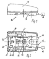
- the seat belt buckle 10 shown in Figure 1 consists of a closure housing 16, which is covered or enclosed by an upper housing cap 11 and a lower housing cap, not shown.
- a connector 12 is provided, via which an electrical connection to a power source or a control unit is provided.
- the seat belt buckle 10 has a push-fit into the closure housing 16 button 13, wherein between the closure housing 16 and this enclosing housing cap 11, a insertion path 14 is recessed for the key 13.
- the button 13 opposite to a tether 15 is attached to the closure housing 16, by means of which the closure 10 can be fastened to a part of the motor vehicle.
- a rigid closure holder may be provided.
- 17 denotes a locking mechanism in the closure housing 16, which cooperates in a conventional manner with a plug in the seat belt buckle 10, not shown locking tongue and locks it; when inserted into the closure 10, the key 13 also cooperates with the locking mechanism 17 in a conventional manner, so that the locking tongue is released again by inserting the key 13.
- an electrically controllable luminescent film attached to the key 13, for example, in the key 13 potted, with this encapsulated, or clipped as a separate component with this.
- a cable connection 21 leads to a receiver 20 arranged laterally in parallel alignment with the outer edge of the housing cap 11.
- the receiver 20 opposite a transmitter 18 is mounted on the inside of the housing cap 11, which has a Cable connection 19 is connected to the connector 12, so that via the connector 12, a corresponding power supply can be made.
- the electrical energy supplied via the plug connector 12 and the cable connection 19 is transmitted by the transmitter 18 without contact to the receiver 20, so that the luminous film 22 is driven.
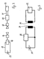
- Figure 3 shows the corresponding circuit with the power source 25 and attached to the housing cap transmitter 18, which is associated with an antenna 26.
- a further antenna 27 is provided, which is connected to the receiver 20, which in turn is connected via the cable connection 21 to the luminous film 22.
- the energy supply 25 formed on the housing side has the energy source 25 with a downstream driver 28, to which a coil 29 on the housing side is connected.
- the coil 29 is associated with a located on the key 13 coil 30 which is connected via the cable connection 21 with the luminous film 22.
Landscapes
- Automotive Seat Belt Assembly (AREA)
- Buckles (AREA)
- Emergency Lowering Means (AREA)
- Lock And Its Accessories (AREA)
Description
- Die Erfindung betrifft einen Sicherheitsgurtverschluß, insbesondere für Kraftfahrzeuge, mit einem Verschlußgehäuse und mit einer Taste zur Betätigung eines im Verschlußgehäuse angeordneten Riegelmechanismus für eine in das Verschlußgehäuse einsteckbare Verschlußzunge, wobei eine Beleuchtung der Taste eingerichtet ist.
- Ein Sicherheitsgurtverschluß mit den vorgenannten Merkmalen ist in der DE-A-39 04 125 beschrieben; hierbei ist eine Lichtquelle beispielsweise in Form einer Leuchtdiode in einem von der Bedientaste entfernt liegenden Bereich des Verschlusses angeordnet und mit der Taste über einen Lichtleitweg aus einem lichtleitenden Material gekoppelt, wobei der Lichtleitweg vorzugsweise aus vorgefertigten, in das Verschlußgehäuse einzusetzenden Materialabschnitten aus einem glasklar-transparenten Material besteht. Bei der bekannten Ausleuchtung der Taste ist bereits eine berührungsfreie Überleitung des Lichtstroms vom Verschlußgehäuse in die Taste ausgebildet.
- Mit dem bekannten Sicherheitsgurtverschluß ist jedoch noch der Nachteil verbunden, daß sowohl die Anordnung der Lichtquelle als auch des Lichtleitweges entsprechend viel Raum erfordern, insbesondere um einen ausreichenden Lichtstrom bis zu der Taste des Verschlusses zu leiten. Damit baut der bekannte Sicherheitsgurtverschluß entsprechend groß. Als weiterer Nachteil ist die große Anfälligkeit des bekannten Sicherheitsgurtverschlusses gegen Verschmutzung zu nennen, da im Lichtleitweg insgesamt vier Lichtaustritts- bzw. Lichteintrittsflächen angeordnet sind, die innerhalb der Schloßkappen liegen und daher nicht gereinigt werden können.
- Der Erfindung liegt daher die Aufgabe zugrunde, bei einem Sicherheitsgurtverschluß mit den gattungsgemäßen Merkmalen eine Ausleuchtung der Taste zu verwirklichen, die ohne eine Vergrößerung der Baugröße gegenüber einem Sicherheitsgurtverschluß ohne Beleuchtung zu realisieren ist.
- Die Lösung dieser Aufgabe ergibt sich einschließlich vorteilhafter Ausgestaltungen und Weiterbildungen der Erfindung aus dem Inhalt der Patentansprüche, welche dieser Beschreibung nachgestellt sind.
- Die Erfindung sieht in ihrem Grundgedanken vor, daß die Taste an ihrer sichtbaren Frontseite mit einer elektrisch ansteuerbaren Leuchtfolie versehen ist und die für die Versorgung der Leuchtfolie erforderliche elektrische Energie von einer an einem feststehenden Teil des Verschlusses angordneten Energiequelle unter Überbrückung eines Luftspaltes auf die Leuchtfolie übertragbar ist. Mit der Erfindung ist der Vorteil verbunden, daß die Leuchtfolie als Lichtquelle praktisch keinen zusätzlichen Platzbedarf erfordert; nach Ausführungsbeispielen der Erfindung ist die Leuchtfolie entweder in der Taste vergossen, mit dieser umspritzt oder als gesondertes Bauteil mit der Taste verklipst. Eine Leuchtfolie mit entsprechender elektrischer Ansteuerung ist als solche für andere Anwendungsbereiche durchaus bekannt. Auch die Versorgung der Leuchtfolie mit elektrischer Energie erfordert keinen zusätzlichen Bauraum, da die Energiequelle außerhalb des Verschlusses angeordnet sein kann. Soweit nach einem Ausführungsbeispiel der Erfindung die elektrische Energie kontaktlos von dem feststehenden Teil des Verschlußgehäuses auf die sich bewegende Taste übertragen wird, ist weiterhin ein gutes Dauerlaufverhalten des Verschlusses wie auch eine hinreichende Staub- und Flüssigkeitsverträglichkeit des Verschlusses gegeben, so daß im Gegensatz zu dem Sicherheitsgurtverschluß nach dem Stand der Technik der erfindungsgemäße Sicherheitsgurtverschluß unempfindlich gegen Verschmutzung ist.
- Nach einem Ausführungsbeispiel der Erfindung ist vorgesehen, daß an dem feststehenden Teil des Verschlusses ein an die Energiequelle angeschlossener Sender vorgesehen ist, dem ein an der Taste angebrachter und elektrisch mit der Leuchtfolie verbundener Empfänger zugeordnet ist, wobei Sender und Empfänger jeweils eine, nach einem Ausführungsbeispiel der Erfindung gegebenenfalls auch als Patch-Antenne ausgebildete Antennen aufweisen können. Alternativ können auch weitere Antennenformen wie Dipolantennen, Wendelantennen, Stab- oder Hornantennen eingesetzt werden.
- In einer alternativen Ausführungsform ist vorgesehen, daß zur kontaktlosen Energieübertragung an dem feststehenden Teil des Verschlusses und an der Taste jeweils eine Spule vorgesehen ist. Hierbei kann vorgesehen sein, daß zwischen Energiequelle und der an dem feststehenden Verschlußteil angeordneten Spule ein Treiber angeordnet ist, wobei dem Treiber noch ein Verstärker nachgeordnet sein kann.
- Nach Ausführungsbeispielen der Erfindung ist das feststehende Teil des Verschlusses entweder das die Verschlußzunge aufnehmende Verschlußgehäuse oder aber die das Verschlußgehäuse umschließende Verschlußkappe, und zwar in der Form als gemeinsam das Verschlußgehäuse bildende obere Verschlußkappe oder untere Verschlußkappe.
- In der Zeichnung ist ein Ausführungsbeispiel der Erfindung wiedergegeben, welches nachstehend beschrieben ist. Es zeigen:
- Fig. 1
- Einen Sicherheitsgurtverschluß in einer Seitenansicht,
- Fig. 2
- den Verschluß gemäß Figur 1 in einer Unteransicht seiner Funktionsteile,
- Fig. 3
- ein erstes Ausführungsbeispiel der Schaltung für die Ausleuchtung der Taste,
- Fig. 4
- ein weiteres Ausführungsbeispiel der Schaltung für die Ausleuchtung der Taste.
- Der in Figur 1 dargestellte Sicherheitsgurtverschluß 10 besteht aus einem Verschlußgehäuse 16, welches von einer oberen Gehäusekappe 11 und einer nicht dargestellten, unteren Gehäusekappe abgedeckt bzw. umschlossen ist. Am hinteren Ende des Sicherheitsgurtverschlusses ist ein Steckverbinder 12 vorgesehen, über den ein elektrischer Anschluß an eine Energiequelle bzw. eine Steuereinheit gegeben ist.
- Wie sich im einzelnen aus Figur 2 entnehmen läßt, weist der Sicherheitsgurtverschluß 10 eine in das Verschlußgehäuse 16 einschiebbare Taste 13 auf, wobei zwischen Verschlußgehäuse 16 und der dieses umschließenden Gehäusekappe 11 ein Einschubweg 14 für die Taste 13 ausgespart ist. Der Taste 13 gegenüberliegend ist an dem Verschlußgehäuse 16 ein Halteseil 15 befestigt, mittels dessen der Verschluß 10 an einem Teil des Kraftfahrzeuges befestigbar ist. Alternativ zum Halteseil kann auch ein starrer Verschlußhalter vorgesehen sein. Weiterhin ist mit 17 in dem Verschlußgehäuse 16 ein Riegelmechanismus bezeichnet, der in an sich bekannter Weise mit einer in den Sicherheitsgurtverschluß 10 einsteckbaren, nicht dargestellten Verschlußzunge zusammenwirkt und diese verriegelt; beim Einschieben in den Verschluß 10 wirkt die Taste 13 ebenfalls mit dem Riegelmechanismus 17 in an sich bekannter Weise zusammen, so daß durch das Einschieben der Taste 13 die Verschlußzunge wieder freigegeben wird.
- Zur Ausleuchtung der Taste 13 ist an der Taste 13 eine elektrisch ansteuerbare Leuchtfolie angebracht, und zwar beispielsweise in der Taste 13 vergossen, mit dieser umspritzt, oder als gesondertes Bauteil mit dieser verklipst. Von der Leuchtfolie 22 führt eine Kabelverbindung 21 zu einem seitwärts, in paralleler Ausrichtung zur Außenkante der Gehäusekappe 11 angeordneten Empfänger 20.
- Dem Empfänger 20 gegenüberliegend ist an der Innenseite der Gehäusekappe 11 ein Sender 18 angebracht, der über eine Kabelverbindung 19 mit dem Steckverbinder 12 verbunden ist, so daß über den Steckverbinder 12 eine entsprechende Energieversorgung erfolgen kann. Die über den Steckverbinder 12 und die Kabelverbindung 19 herangeführte elektrische Energie wird von dem Sender 18 berührungslos auf den Empfänger 20 übertragen, so daß die Leuchtfolie 22 angesteuert wird.
- Entsprechend dem in Figur 2 dargestellten Ausführungsbeispiel zeigt Figur 3 die entsprechende Schaltung mit der Energiequelle 25 und dem an der Gehäusekappe angebrachten Sender 18, dem eine Antenne 26 zugeordnet ist. Tastenseitig ist eine weitere Antenne 27 vorgesehen, die mit dem Empfänger 20 verbunden ist, der seinerseits über die Kabelverbindung 21 an die Leuchtfolie 22 angeschlossen ist.
- In einer alternativen Schaltung weist die gehäuseseitig ausgebildete Energieversorgung die Energiequelle 25 mit einem nachgeschalteten Treiber 28 auf, dem eine gehäuseseitige Spule 29 zugeschaltet ist. Der Spule 29 ist eine an der Taste 13 befindliche Spule 30 zugeordnet, die über die Kabelverbindung 21 mit der Leuchtfolie 22 verbunden ist.
- Die in der vorstehenden Beschreibung, den Patentansprüchen, der Zusammenfassung und der Zeichnung offenbarten Merkmale des Gegenstandes dieser Unterlagen können sowohl einzeln als auch in beliebigen Kombinationen untereinander für die Verwirklichung der Erfindung in ihren verschiedenen Ausführungsformen wesentlich sein.
Claims (12)
- Sicherheitsgurtverschluß, insbesondere für Kraftfahrzeuge, mit einem Verschlußgehäuse (16) und mit einer Taste (13) zur Betätigung eines im Verschlußgehäuse (16) angeordneten Riegelmechanismus (17) für eine in das Verschlußgehäuse (16) einsteckbare Verschlußzunge, wobei eine Beleuchtung der Taste (13) eingerichtet ist, dadurch gekennzeichnet, daß die Taste (13) an ihrer sichtbaren Frontseite mit einer elektrisch ansteuerbaren Leuchtfolie (22) versehen ist und die für die Versorgung der Leuchtfolie (22) erforderliche elektrische Energie von einer an einem feststehenden Teil des Verschlusses (10) angordneten Energiequelle (25) unter Überbrückung eines Luftspaltes auf die Leuchtfolie (22) übertragbar ist.
- Sicherheitsgurtverschluß nach Anspruch 1, dadurch gekennzeichnet, dass die erforderliche elektrische Energie kontaktlos auf die Leuchtfolie übertragbar ist.
- Sicherheitsgurtverschluß nach Anspruch 2, dadurch gekennzeichnet, daß an dem feststehenden Teil des Verschlusses (10) ein an die Energiequelle (25) angeschlossener Sender (18) vorgesehen ist, dem ein an der Taste (13) angebrachter und elektrisch mit der Leuchtfolie (22) verbundener Empfänger (20) zugeordnet ist.
- Sicherheitsgurtverschluß nach Anspruch 3, dadurch gekennzeichnet, daß Sender (18) und Empfänger (20) jeweils eine Antenne (26, 27) aufweisen.
- Sicherheitsgurtverschluß nach Anspruch 4, dadurch gekennzeichnet, daß die Antennen (26, 27) als Patch-Antennen ausgebildet sind.
- Sicherheitsgurtverschluß nach Anspruch 2, dadurch gekennzeichnet, daß zur kontaktlosen Energieübertragung an dem feststehenden Teil des Verschlusses (10) und an der Taste (13) jeweils eine Spule (29, 30) vorgesehen ist.
- Sicherheitsgurtverschluß nach Anspruch 6, dadurch gekennzeichnet, daß zwischen Energiequelle (25) und der an dem feststehenden Verschlußteil angeordneten Spule (29) ein Treiber (28) angeordnet ist.
- Sicherheitsgurtverschluß nach Anspruch 7, dadurch gekennzeichnet, daß dem Treiber (28) ein Verstärker nachgeordnet ist.
- Sicherheitsgurtverschluß nach einem der Ansprüche 1 bis 8, dadurch gekennzeichnet, daß die Leuchtfolie (22) in der Taste (13) vergossen ist.
- Sicherheitsgurtverschluß nach einem der Ansprüche 1 bis 8, dadurch gekennzeichnet, daß die Leuchtfolie (22) mit der Taste (13) verklipst ist.
- Sicherheitsgurtverschluß nach einem der Ansprüche 1 bis 10, dadurch gekennzeichnet, daß das feststehende Teil des Verschlusses (10) das die Verschlußzunge aufnehmende Verschlußgehäuse (16) ist.
- Sicherheitsgurtverschluß nach einem der Ansprüche 1 bis 10, dadurch gekennzeichnet, daß das feststehende Teil des Verschlusses (10) eine das Verschlußgehäuse (16) umschließende Verschlußkappe (11) ist.
Applications Claiming Priority (3)
| Application Number | Priority Date | Filing Date | Title |
|---|---|---|---|
| DE10228669 | 2002-06-27 | ||
| DE10228669A DE10228669C1 (de) | 2002-06-27 | 2002-06-27 | Sicherheitsgurtverschluß mit ausgeleuchteter Bedientaste |
| PCT/EP2003/006228 WO2004002256A1 (de) | 2002-06-27 | 2003-06-13 | Sicherheitsgurtverschluss mit ausgeleuchteter bedientaste |
Publications (2)
| Publication Number | Publication Date |
|---|---|
| EP1515625A1 EP1515625A1 (de) | 2005-03-23 |
| EP1515625B1 true EP1515625B1 (de) | 2006-11-08 |
Family
ID=7714712
Family Applications (1)
| Application Number | Title | Priority Date | Filing Date |
|---|---|---|---|
| EP03740240A Expired - Lifetime EP1515625B1 (de) | 2002-06-27 | 2003-06-13 | Sicherheitsgurtverschluss mit ausgeleuchteter bedientaste |
Country Status (7)
| Country | Link |
|---|---|
| EP (1) | EP1515625B1 (de) |
| JP (1) | JP2005530570A (de) |
| AT (1) | ATE344626T1 (de) |
| AU (1) | AU2003280439A1 (de) |
| DE (2) | DE10228669C1 (de) |
| ES (1) | ES2276088T3 (de) |
| WO (1) | WO2004002256A1 (de) |
Families Citing this family (6)
| Publication number | Priority date | Publication date | Assignee | Title |
|---|---|---|---|---|
| DE10338897A1 (de) * | 2003-08-23 | 2005-03-17 | Volkswagen Ag | Beleuchtbares Funktionselement für ein Kraftfahrzeug |
| JP2007014359A (ja) | 2005-06-15 | 2007-01-25 | Takata Corp | バックル装置及びシートベルト装置 |
| KR101565744B1 (ko) | 2013-10-14 | 2015-11-04 | 곽기춘 | 기능성 디지털 버클 |
| DE102015215254B4 (de) * | 2015-08-11 | 2022-03-10 | Autoliv Development Ab | Beleuchtetes Gurtschloss für eine Sicherheitsgurteinrichtung eines Kraftfahrzeuges |
| EP3349609A1 (de) | 2015-09-17 | 2018-07-25 | Key Safety Systems, Inc. | Beleuchtete sitzgurtschnalle |
| DE102021106000B3 (de) * | 2021-03-11 | 2022-02-10 | Autoliv Development Ab | Schlosszunge, Sicherheitsgurt und Sicherheitsgurtsystem |
Family Cites Families (4)
| Publication number | Priority date | Publication date | Assignee | Title |
|---|---|---|---|---|
| SE450331B (sv) * | 1983-03-03 | 1987-06-22 | Stil Ind Ab | Bilbelteslas med elektrisk kontakt |
| DE3904125A1 (de) * | 1988-02-13 | 1989-08-24 | Autoflug Gmbh | Ausgeleuchteter sicherheitsgurtverschluss |
| DE19702751A1 (de) * | 1997-01-27 | 1998-07-30 | Lumino Gmbh Licht Elektronik | Vorrichtung zur Anzeige von alpha-numerischen Zeichen und/oder Bildzeichen |
| DE19959007C1 (de) * | 1999-12-08 | 2000-08-31 | Daimler Chrysler Ag | Vorrichtung zur Unterstützung der Gurtzuführung für Sicherheitsgurte |
-
2002
- 2002-06-27 DE DE10228669A patent/DE10228669C1/de not_active Expired - Fee Related
-
2003
- 2003-06-13 EP EP03740240A patent/EP1515625B1/de not_active Expired - Lifetime
- 2003-06-13 ES ES03740240T patent/ES2276088T3/es not_active Expired - Lifetime
- 2003-06-13 AU AU2003280439A patent/AU2003280439A1/en not_active Abandoned
- 2003-06-13 DE DE50305642T patent/DE50305642D1/de not_active Expired - Lifetime
- 2003-06-13 JP JP2004516588A patent/JP2005530570A/ja active Pending
- 2003-06-13 AT AT03740240T patent/ATE344626T1/de not_active IP Right Cessation
- 2003-06-13 WO PCT/EP2003/006228 patent/WO2004002256A1/de not_active Ceased
Also Published As
| Publication number | Publication date |
|---|---|
| DE10228669C1 (de) | 2003-04-24 |
| EP1515625A1 (de) | 2005-03-23 |
| WO2004002256A1 (de) | 2004-01-08 |
| AU2003280439A1 (en) | 2004-01-19 |
| ATE344626T1 (de) | 2006-11-15 |
| DE50305642D1 (de) | 2006-12-21 |
| ES2276088T3 (es) | 2007-06-16 |
| JP2005530570A (ja) | 2005-10-13 |
Similar Documents
| Publication | Publication Date | Title |
|---|---|---|
| DE60313044T2 (de) | Mehrachsige Schleifenantenne in Chip-Form | |
| EP3331103B1 (de) | Elektrisches steckverbindungssystem zum elektrischen anschluss eines anhängers an ein zugfahrzeug | |
| DE102015215254B4 (de) | Beleuchtetes Gurtschloss für eine Sicherheitsgurteinrichtung eines Kraftfahrzeuges | |
| DE2914643A1 (de) | Automatik-sicherheitsgurt | |
| DE102020133574B4 (de) | Sicherheitsgurtvorrichtung | |
| DE602004007072T2 (de) | Ionengeneratoreinheit | |
| DE4432000A1 (de) | Drahtlos gesteuerte Wegfahrsperre für ein Kraftfahrzeug | |
| DE69420946T2 (de) | Antidiebstahlvorrichtung | |
| DE10228669C1 (de) | Sicherheitsgurtverschluß mit ausgeleuchteter Bedientaste | |
| DE2460449A1 (de) | Gurtschloss fuer fahrzeugsicherheitsgurte | |
| DE102010055206A1 (de) | Bordinformationssystem mit Mobilfunkantenne | |
| DE3725467A1 (de) | Schutzvorrichtung fuer ein flexibles elektrisches kabel | |
| EP3440291B1 (de) | Kraftfahrzeugschloss | |
| DE102016117099A1 (de) | Gurtschloss mit Beleuchtung | |
| DE102021106000B3 (de) | Schlosszunge, Sicherheitsgurt und Sicherheitsgurtsystem | |
| DE2845587C2 (de) | Auf einer Tragschiene montierbare elektrische Reihenklemme | |
| DE102010033385A1 (de) | Haltewunschtaster zur Anordnung an Haltestangen in Fahrzeugen | |
| DE10142713A1 (de) | Zugangskontrollkarte, insbesondere für den Zugang zu einem Kraftfahrzeug | |
| DE4213508C1 (en) | Anti-theft device for a vehicle - has split cables between internal handles and locks with remote-controlled coupling device for cable ends | |
| DE9107244U1 (de) | Elektronisches, berührungslos wirkendes Schaltgerät | |
| EP1002367B1 (de) | Schaltsystem mit lichtleiter | |
| DE3410344A1 (de) | Beleuchtetes elektrisches installationsgeraet | |
| DE636564C (de) | Richtungsanzeiger mit elektrischer Beleuchtung, der am Handgelenk oder am Arm anschnallbar ist | |
| DE69304188T2 (de) | Verfahren und Vorrichtung zum Vermeiden von Betrügereien an Taxametern oder Fahrtenschreibern | |
| DE8508487U1 (de) | Fahrzeugleuchte |
Legal Events
| Date | Code | Title | Description |
|---|---|---|---|
| PUAI | Public reference made under article 153(3) epc to a published international application that has entered the european phase |
Free format text: ORIGINAL CODE: 0009012 |
|
| 17P | Request for examination filed |
Effective date: 20041216 |
|
| AK | Designated contracting states |
Kind code of ref document: A1 Designated state(s): AT BE BG CH CY CZ DE DK EE ES FI FR GB GR HU IE IT LI LU MC NL PT RO SE SI SK TR |
|
| AX | Request for extension of the european patent |
Extension state: AL LT LV MK |
|
| DAX | Request for extension of the european patent (deleted) | ||
| GRAP | Despatch of communication of intention to grant a patent |
Free format text: ORIGINAL CODE: EPIDOSNIGR1 |
|
| RIN1 | Information on inventor provided before grant (corrected) |
Inventor name: LANGHOFF, HANS-JOERG Inventor name: WORMS, MARTIN |
|
| GRAS | Grant fee paid |
Free format text: ORIGINAL CODE: EPIDOSNIGR3 |
|
| GRAA | (expected) grant |
Free format text: ORIGINAL CODE: 0009210 |
|
| AK | Designated contracting states |
Kind code of ref document: B1 Designated state(s): AT BE BG CH CY CZ DE DK EE ES FI FR GB GR HU IE IT LI LU MC NL PT RO SE SI SK TR |
|
| PG25 | Lapsed in a contracting state [announced via postgrant information from national office to epo] |
Ref country code: NL Free format text: LAPSE BECAUSE OF FAILURE TO SUBMIT A TRANSLATION OF THE DESCRIPTION OR TO PAY THE FEE WITHIN THE PRESCRIBED TIME-LIMIT Effective date: 20061108 Ref country code: SK Free format text: LAPSE BECAUSE OF FAILURE TO SUBMIT A TRANSLATION OF THE DESCRIPTION OR TO PAY THE FEE WITHIN THE PRESCRIBED TIME-LIMIT Effective date: 20061108 Ref country code: SI Free format text: LAPSE BECAUSE OF FAILURE TO SUBMIT A TRANSLATION OF THE DESCRIPTION OR TO PAY THE FEE WITHIN THE PRESCRIBED TIME-LIMIT Effective date: 20061108 Ref country code: IE Free format text: LAPSE BECAUSE OF FAILURE TO SUBMIT A TRANSLATION OF THE DESCRIPTION OR TO PAY THE FEE WITHIN THE PRESCRIBED TIME-LIMIT Effective date: 20061108 Ref country code: FI Free format text: LAPSE BECAUSE OF FAILURE TO SUBMIT A TRANSLATION OF THE DESCRIPTION OR TO PAY THE FEE WITHIN THE PRESCRIBED TIME-LIMIT Effective date: 20061108 Ref country code: CZ Free format text: LAPSE BECAUSE OF FAILURE TO SUBMIT A TRANSLATION OF THE DESCRIPTION OR TO PAY THE FEE WITHIN THE PRESCRIBED TIME-LIMIT Effective date: 20061108 Ref country code: RO Free format text: LAPSE BECAUSE OF FAILURE TO SUBMIT A TRANSLATION OF THE DESCRIPTION OR TO PAY THE FEE WITHIN THE PRESCRIBED TIME-LIMIT Effective date: 20061108 |
|
| REG | Reference to a national code |
Ref country code: GB Ref legal event code: FG4D Free format text: NOT ENGLISH |
|
| REG | Reference to a national code |
Ref country code: CH Ref legal event code: EP |
|
| REG | Reference to a national code |
Ref country code: IE Ref legal event code: FG4D Free format text: LANGUAGE OF EP DOCUMENT: GERMAN |
|
| REF | Corresponds to: |
Ref document number: 50305642 Country of ref document: DE Date of ref document: 20061221 Kind code of ref document: P |
|
| PG25 | Lapsed in a contracting state [announced via postgrant information from national office to epo] |
Ref country code: DK Free format text: LAPSE BECAUSE OF FAILURE TO SUBMIT A TRANSLATION OF THE DESCRIPTION OR TO PAY THE FEE WITHIN THE PRESCRIBED TIME-LIMIT Effective date: 20070208 Ref country code: BG Free format text: LAPSE BECAUSE OF FAILURE TO SUBMIT A TRANSLATION OF THE DESCRIPTION OR TO PAY THE FEE WITHIN THE PRESCRIBED TIME-LIMIT Effective date: 20070208 Ref country code: SE Free format text: LAPSE BECAUSE OF FAILURE TO SUBMIT A TRANSLATION OF THE DESCRIPTION OR TO PAY THE FEE WITHIN THE PRESCRIBED TIME-LIMIT Effective date: 20070208 |
|
| GBT | Gb: translation of ep patent filed (gb section 77(6)(a)/1977) |
Effective date: 20070206 |
|
| PG25 | Lapsed in a contracting state [announced via postgrant information from national office to epo] |
Ref country code: PT Free format text: LAPSE BECAUSE OF FAILURE TO SUBMIT A TRANSLATION OF THE DESCRIPTION OR TO PAY THE FEE WITHIN THE PRESCRIBED TIME-LIMIT Effective date: 20070409 |
|
| NLV1 | Nl: lapsed or annulled due to failure to fulfill the requirements of art. 29p and 29m of the patents act | ||
| ET | Fr: translation filed | ||
| REG | Reference to a national code |
Ref country code: ES Ref legal event code: FG2A Ref document number: 2276088 Country of ref document: ES Kind code of ref document: T3 |
|
| REG | Reference to a national code |
Ref country code: IE Ref legal event code: FD4D |
|
| PLBE | No opposition filed within time limit |
Free format text: ORIGINAL CODE: 0009261 |
|
| STAA | Information on the status of an ep patent application or granted ep patent |
Free format text: STATUS: NO OPPOSITION FILED WITHIN TIME LIMIT |
|
| 26N | No opposition filed |
Effective date: 20070809 |
|
| BERE | Be: lapsed |
Owner name: AUTOLIV DEVELOPMENT A.B. Effective date: 20070630 |
|
| PG25 | Lapsed in a contracting state [announced via postgrant information from national office to epo] |
Ref country code: MC Free format text: LAPSE BECAUSE OF NON-PAYMENT OF DUE FEES Effective date: 20070630 |
|
| REG | Reference to a national code |
Ref country code: CH Ref legal event code: PL |
|
| PG25 | Lapsed in a contracting state [announced via postgrant information from national office to epo] |
Ref country code: BE Free format text: LAPSE BECAUSE OF NON-PAYMENT OF DUE FEES Effective date: 20070630 |
|
| PG25 | Lapsed in a contracting state [announced via postgrant information from national office to epo] |
Ref country code: CH Free format text: LAPSE BECAUSE OF NON-PAYMENT OF DUE FEES Effective date: 20070630 Ref country code: GR Free format text: LAPSE BECAUSE OF FAILURE TO SUBMIT A TRANSLATION OF THE DESCRIPTION OR TO PAY THE FEE WITHIN THE PRESCRIBED TIME-LIMIT Effective date: 20070209 Ref country code: LI Free format text: LAPSE BECAUSE OF NON-PAYMENT OF DUE FEES Effective date: 20070630 |
|
| PG25 | Lapsed in a contracting state [announced via postgrant information from national office to epo] |
Ref country code: AT Free format text: LAPSE BECAUSE OF NON-PAYMENT OF DUE FEES Effective date: 20070613 |
|
| PG25 | Lapsed in a contracting state [announced via postgrant information from national office to epo] |
Ref country code: EE Free format text: LAPSE BECAUSE OF FAILURE TO SUBMIT A TRANSLATION OF THE DESCRIPTION OR TO PAY THE FEE WITHIN THE PRESCRIBED TIME-LIMIT Effective date: 20061108 |
|
| PG25 | Lapsed in a contracting state [announced via postgrant information from national office to epo] |
Ref country code: LU Free format text: LAPSE BECAUSE OF NON-PAYMENT OF DUE FEES Effective date: 20070613 Ref country code: CY Free format text: LAPSE BECAUSE OF FAILURE TO SUBMIT A TRANSLATION OF THE DESCRIPTION OR TO PAY THE FEE WITHIN THE PRESCRIBED TIME-LIMIT Effective date: 20061108 |
|
| PG25 | Lapsed in a contracting state [announced via postgrant information from national office to epo] |
Ref country code: HU Free format text: LAPSE BECAUSE OF FAILURE TO SUBMIT A TRANSLATION OF THE DESCRIPTION OR TO PAY THE FEE WITHIN THE PRESCRIBED TIME-LIMIT Effective date: 20070509 Ref country code: TR Free format text: LAPSE BECAUSE OF FAILURE TO SUBMIT A TRANSLATION OF THE DESCRIPTION OR TO PAY THE FEE WITHIN THE PRESCRIBED TIME-LIMIT Effective date: 20061108 |
|
| PGFP | Annual fee paid to national office [announced via postgrant information from national office to epo] |
Ref country code: GB Payment date: 20100401 Year of fee payment: 8 |
|
| PG25 | Lapsed in a contracting state [announced via postgrant information from national office to epo] |
Ref country code: IT Free format text: LAPSE BECAUSE OF NON-PAYMENT OF DUE FEES Effective date: 20090613 |
|
| PGRI | Patent reinstated in contracting state [announced from national office to epo] |
Ref country code: IT Effective date: 20110616 |
|
| GBPC | Gb: european patent ceased through non-payment of renewal fee |
Effective date: 20110613 |
|
| PG25 | Lapsed in a contracting state [announced via postgrant information from national office to epo] |
Ref country code: GB Free format text: LAPSE BECAUSE OF NON-PAYMENT OF DUE FEES Effective date: 20110613 |
|
| REG | Reference to a national code |
Ref country code: FR Ref legal event code: PLFP Year of fee payment: 14 |
|
| REG | Reference to a national code |
Ref country code: FR Ref legal event code: PLFP Year of fee payment: 15 |
|
| REG | Reference to a national code |
Ref country code: FR Ref legal event code: PLFP Year of fee payment: 16 |
|
| PGFP | Annual fee paid to national office [announced via postgrant information from national office to epo] |
Ref country code: FR Payment date: 20200629 Year of fee payment: 18 |
|
| PGFP | Annual fee paid to national office [announced via postgrant information from national office to epo] |
Ref country code: ES Payment date: 20200717 Year of fee payment: 18 |
|
| PGFP | Annual fee paid to national office [announced via postgrant information from national office to epo] |
Ref country code: IT Payment date: 20200630 Year of fee payment: 18 |
|
| PG25 | Lapsed in a contracting state [announced via postgrant information from national office to epo] |
Ref country code: FR Free format text: LAPSE BECAUSE OF NON-PAYMENT OF DUE FEES Effective date: 20210630 |
|
| PGFP | Annual fee paid to national office [announced via postgrant information from national office to epo] |
Ref country code: DE Payment date: 20220621 Year of fee payment: 20 |
|
| REG | Reference to a national code |
Ref country code: ES Ref legal event code: FD2A Effective date: 20220803 |
|
| PG25 | Lapsed in a contracting state [announced via postgrant information from national office to epo] |
Ref country code: ES Free format text: LAPSE BECAUSE OF NON-PAYMENT OF DUE FEES Effective date: 20210614 |
|
| REG | Reference to a national code |
Ref country code: DE Ref legal event code: R071 Ref document number: 50305642 Country of ref document: DE |
|
| PG25 | Lapsed in a contracting state [announced via postgrant information from national office to epo] |
Ref country code: IT Free format text: LAPSE BECAUSE OF NON-PAYMENT OF DUE FEES Effective date: 20210630 |