EP1515056B1 - Kran mit Gleitelement - Google Patents
Kran mit Gleitelement Download PDFInfo
- Publication number
- EP1515056B1 EP1515056B1 EP03450193A EP03450193A EP1515056B1 EP 1515056 B1 EP1515056 B1 EP 1515056B1 EP 03450193 A EP03450193 A EP 03450193A EP 03450193 A EP03450193 A EP 03450193A EP 1515056 B1 EP1515056 B1 EP 1515056B1
- Authority
- EP
- European Patent Office
- Prior art keywords
- gliding
- sliding
- crane
- spring
- crane according
- Prior art date
- Legal status (The legal status is an assumption and is not a legal conclusion. Google has not performed a legal analysis and makes no representation as to the accuracy of the status listed.)
- Expired - Lifetime
Links
- 239000000314 lubricant Substances 0.000 claims description 3
- 239000002184 metal Substances 0.000 description 4
- 230000000694 effects Effects 0.000 description 2
- 230000013011 mating Effects 0.000 description 2
- 230000007547 defect Effects 0.000 description 1
- 238000006073 displacement reaction Methods 0.000 description 1
- 239000003292 glue Substances 0.000 description 1
- 238000012423 maintenance Methods 0.000 description 1
- 239000000725 suspension Substances 0.000 description 1
Images


Classifications
-
- F—MECHANICAL ENGINEERING; LIGHTING; HEATING; WEAPONS; BLASTING
- F16—ENGINEERING ELEMENTS AND UNITS; GENERAL MEASURES FOR PRODUCING AND MAINTAINING EFFECTIVE FUNCTIONING OF MACHINES OR INSTALLATIONS; THERMAL INSULATION IN GENERAL
- F16C—SHAFTS; FLEXIBLE SHAFTS; ELEMENTS OR CRANKSHAFT MECHANISMS; ROTARY BODIES OTHER THAN GEARING ELEMENTS; BEARINGS
- F16C29/00—Bearings for parts moving only linearly
- F16C29/02—Sliding-contact bearings
-
- B—PERFORMING OPERATIONS; TRANSPORTING
- B66—HOISTING; LIFTING; HAULING
- B66C—CRANES; LOAD-ENGAGING ELEMENTS OR DEVICES FOR CRANES, CAPSTANS, WINCHES, OR TACKLES
- B66C23/00—Cranes comprising essentially a beam, boom, or triangular structure acting as a cantilever and mounted for translatory of swinging movements in vertical or horizontal planes or a combination of such movements, e.g. jib-cranes, derricks, tower cranes
- B66C23/62—Constructional features or details
- B66C23/64—Jibs
- B66C23/68—Jibs foldable or otherwise adjustable in configuration
-
- B—PERFORMING OPERATIONS; TRANSPORTING
- B66—HOISTING; LIFTING; HAULING
- B66C—CRANES; LOAD-ENGAGING ELEMENTS OR DEVICES FOR CRANES, CAPSTANS, WINCHES, OR TACKLES
- B66C23/00—Cranes comprising essentially a beam, boom, or triangular structure acting as a cantilever and mounted for translatory of swinging movements in vertical or horizontal planes or a combination of such movements, e.g. jib-cranes, derricks, tower cranes
- B66C23/62—Constructional features or details
- B66C23/64—Jibs
- B66C23/70—Jibs constructed of sections adapted to be assembled to form jibs or various lengths
- B66C23/701—Jibs constructed of sections adapted to be assembled to form jibs or various lengths telescopic
- B66C23/707—Jibs constructed of sections adapted to be assembled to form jibs or various lengths telescopic guiding devices for telescopic jibs
-
- F—MECHANICAL ENGINEERING; LIGHTING; HEATING; WEAPONS; BLASTING
- F16—ENGINEERING ELEMENTS AND UNITS; GENERAL MEASURES FOR PRODUCING AND MAINTAINING EFFECTIVE FUNCTIONING OF MACHINES OR INSTALLATIONS; THERMAL INSULATION IN GENERAL
- F16C—SHAFTS; FLEXIBLE SHAFTS; ELEMENTS OR CRANKSHAFT MECHANISMS; ROTARY BODIES OTHER THAN GEARING ELEMENTS; BEARINGS
- F16C2326/00—Articles relating to transporting
Definitions
- the present invention relates to a crane with a telescopic crane arm with at least two mutually displaceable push arms, wherein between the push arms at least one sliding element is arranged, which is loosely mounted in a frame.
- a crane is known from WO 95/16145 A1.
- Object of the present invention is to further develop the known sliding elements to the effect that both a stable storage and a rapid interchangeability are ensured.
- the sliding element By over the sliding surface of the sliding element projecting spring element, the sliding element is always pressed with the side facing away from the sliding surface side on the support surface, whereby a leaving even very low trained holding frame is prevented.
- the spring element is designed as a leaf spring.
- the spring element is mounted in a recess in the sliding element.
- the sliding member 2 consists of a flat plastic block.
- recesses 7 are incorporated in the form of elongated grooves that can accommodate lubricant.
- the recesses 7 are filled with lubricant to reduce the coefficient of friction in addition.
- the sliding element 2 has a central recess 5 into which a spring element 4 in the form of a prestressed leaf spring is inserted.
- This spring shape has proven particularly useful. However, it is also conceivable spiral springs and any other suspensions that are comparable in their effect.
- the leaf spring is secured at its ends by the projections 6 against falling out and is in the central region on the sliding surface 3 of the sliding element 2 clearly above. Even if the mating surface lifts off the sliding surface 3 of the sliding element 2, the spring element 4 ensures that the sliding element 2 is still subjected to pressure and is thereby pressed onto the ground.
- the provided around the slider 2 metal frame 8 can therefore be made very low, to ensure that it never comes into contact with the mating surface.
- Both the leaf spring can be easily replaced in case of a defect, as well as the sliding member 2, which rests only loosely in the frame 8, with the lower surface is not screwed or glued.
Landscapes
- Engineering & Computer Science (AREA)
- Mechanical Engineering (AREA)
- General Engineering & Computer Science (AREA)
- Jib Cranes (AREA)
- Springs (AREA)
- Bearings For Parts Moving Linearly (AREA)
- Leg Units, Guards, And Driving Tracks Of Cranes (AREA)
Description
- Die vorliegende Erfindung betrifft einen Kran mit einem teleskopierbaren Kranarm mit mindestens zwei gegeneinander verschiebbaren Schubarmen, wobei zwischen den Schubarmen mindestens ein Gleitelement angeordnet ist, das in einem Rahmen lose gelagert ist. Ein solcher Kran ist aus WO 95/16145 A1 bekannt.
- Zwischen zwei Schubarmen angeordnete Gleitelemente sollen den Reibungswiderstand beim gegenseitigen Verschieben der Schubarme beim Ein- und Ausfahren gering halten. Dabei ist wesentlich, dass die Gleitelemente an vorbestimmten Stellen unverrückbar gelagert sind, um in jeder Relativposition der Schubarme wirksam zu sein. Es wurde daher bereits vorgeschlagen, die Gleitelemente mit einem der Schubarme zu verkleben oder zu verschrauben. Da sich die Gleitelemente jedoch mit der Zeit abnützen und ausgetauscht werden müssen, ist diese Art der Befestigung ungünstig für eine rasche und problemlose Austauschbarkeit.
- Alternativ dazu wurde versucht, die Gleitelemente in einem Metallrahmen zu halten, wobei der Metallrahmen deutlich niedriger als die Dicke der Gleitelemente ausgebildet sein muss, um nicht bei der Relativbewegung der Schubarme mit der Gegenfläche in Kontakt zu kommen. Dies hat zur Folge, dass in der Vergangenheit manchmal abgenützte Gleitelemente über den niedrigen Metallrahmen hinweg aus der Lagerstelle herausgeschoben wurden.
- Aufgabe der vorliegenden Erfindung ist es, die bekannten Gleitelemente dahingehend weiter zu entwickeln, dass sowohl eine stabile Lagerung sowie auch eine rasche Austauschbarkeit sichergestellt sind.
- Dies wird erfindungsgemäß dadurch erreicht, dass das Gleitelement ein über die Gleitfläche des Gleitelementes vorstehendes, gesondertes Federelement aufweist.
- Durch das über die Gleitfläche des Gleitelementes vorstehende Federelement wird das Gleitelement immer mit der von der Gleitfläche abgewandten Seite auf die Auflagefläche gedrückt, wodurch ein Verlassen auch sehr niedrig ausgebildeter Halterahmen verhindert wird.
- In einer besonders einfachen und stabilen Ausführungsform ist das Federelement als Blattfeder ausgebildet.
- Um die Kontaktfläche des Federelementes mit der Gegenfläche möglichst gering zu halten, ist es günstig, wenn das Federelement in einer Ausnehmung im Gleitelement gelagert ist.
- Die Funktionssicherheit lässt sich dadurch erhöhen, dass das Federelement insbesondere durch seitliche Vorsprünge von der Wand der Ausnehmung gegen Herausfallen gesichert ist.
- Vorzugsweise wird das Gleitelement aus Kunststoff hergestellt. In diesem Zusammenhang ergibt sich die Möglichkeit, statt der Blattfeder mitgespritzte Federelemente aus Kunststoff vorzusehen.
- Weitere Vorteile und Einzelheiten der vorliegenden Erfindung ergeben sich aus der nachfolgenden Figurenbeschreibung. Dabei zeigt:
- Fig. 1 einen Schubrahmen eines teleskopierbaren Kranarmes, in dem zwei Gleitelemente gelagert sind,
- Fig. 2a einen Längsschnitt durch zwei im Querschnitt rechteckige Schubarme beim Lastfall "Heben",
- Fig. 2b einen Längsschnitt durch diese Schubarme beim Lastfall "Drücken" und
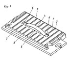
- Fig. 3 eine perspektivische Detailansicht eines in einem Rahmen gelagerten Gleitelements.
- In den Figuren 1, 2a und 2b sind zwei Schubarme eines teleskopierbaren Kranarmes in vereinfachter Form dargestellt. Der in Fig. 1 gezeigte Schubarm 1a weist einen sechseckigen Querschnitt auf, sodass die Gleitelemente 2 jeweils paarweise in den beiden Boden- und Deckflächen angeordnet sind. Figuren 2a und 2b gehen hingegen von einem rechteckigen Querschnitt der Schubarme 1a und 1b aus, sodass jede Lagerstelle von einem einzigen Gleitelement 2 gebildet wird.
- Die Schubarme 1a und 1b sind in Längsrichtung gegeneinander verschiebbar. Bei dem in Fig. 2a dargestellten Lastfall, bei dem eine Last eine Kraft in Richtung des Pfeils 10 aufbringt, wird der innere Schubarm 1b gegen die Lagerstellen links oben und rechts unten gedrückt. Im umgekehrten, eher seltenen Fall, der in Fig. 2b dargestellt ist, wirkt die Kraft in Richtung des Pfeils 11. In diesem Fall werden die Hilfsgleitelemente 9 beansprucht, die aufgrund der Seltenheit dieses Lastfalls normalerweise wesentlich einfacher gestaltet sind, als die Gleitelemente 2. Die Hilfsgleitelemente 9 müssen auch kaum ausgetauscht werden.
- Wie Fig. 3 im Detail zeigt, besteht das Gleitelement 2 aus einem flachen Kunststoffblock. In die Gleitfläche 3 sind Vertiefungen 7 in Form länglicher Nuten eingearbeitet, die Schmiermittel aufnehmen können. Im Neuzustand und nach jeder Wartung werden die Vertiefungen 7 mit Schmiermittel gefüllt, um den Reibungskoeffizienten zusätzlich herabzusetzen.
- Das Gleitelement 2 weist eine zentrale Ausnehmung 5 auf, in die ein Federelement 4 in Form einer vorgespannten Blattfeder eingesetzt ist. Diese Federform hat sich besonders bewährt. Es sind jedoch auch Spiralfedern und beliebige andere Federungen vorstellbar, die in ihrer Wirkung vergleichbar sind. Die Blattfeder wird an ihren Enden durch die Vorsprünge 6 gegen Herausfallen gesichert und steht im Mittelbereich über die Gleitfläche 3 des Gleitelementes 2 deutlich über. Selbst wenn die Gegenfläche von der Gleitfläche 3 des Gleitelementes 2 abhebt, stellt das Federelement 4 sicher, dass das Gleitelement 2 nach wie vor mit Druck beaufschlagt ist und dadurch auf den Untergrund gepresst wird. Der um das Gleitelement 2 vorgesehene Metallrahmen 8 kann daher sehr nieder ausgebildet werden, um sicherzustellen, dass er keinesfalls mit der Gegenfläche in Kontakt kommt.
- Sowohl die Blattfeder kann bei einem Defekt leicht ausgetauscht werden, wie auch das Gleitelement 2, das lediglich lose im Rahmen 8 ruht, mit der Unterfläche jedoch nicht verschraubt oder verklebt ist.
Claims (6)
- Kran mit einem teleskopierbaren Kranarm mit mindestens zwei gegeneinander verschiebbaren Schubarmen (1a, 1b), wobei zwischen den Schubarmen (1a, 1b) mindestens ein Gleitelement (2) angeordnet ist, das in einem Rahmen (8) lose gelagert ist, dadurch gekennzeichnet, dass das Gleitelement (2) ein über die Gleitfläche (3) des Gleitelements (2) vorstehendes, gesondertes Federelement (4) aufweist.
- Kran nach Anspruch 1, dadurch gekennzeichnet, dass das Federelement (4) als Blattfeder ausgebildet ist.
- Kran nach Anspruch 1 oder 2, dadurch gekennzeichnet, dass das Federelement (4) insbesondere in einer Ausnehmung (5) im Gleitelement (2) gelagert ist.
- Kran nach einem der Ansprüche 1 bis 3, dadurch gekennzeichnet, dass das Federelement (4) insbesondere durch seitliche Vorsprünge (6) von der Wand der Ausnehmung (5) gegen Herausfallen gesichert ist.
- Kran nach einem der Ansprüche 1 bis 4, dadurch gekennzeichnet, dass in der Gleitfläche (3) Vertiefungen (7) für Schmiermittel vorgesehen sind.
- Kran nach einem der Ansprüche 1 bis 5, dadurch gekennzeichnet, dass das Gleitelement aus Kunststoff ist.
Priority Applications (8)
| Application Number | Priority Date | Filing Date | Title |
|---|---|---|---|
| DE50305368T DE50305368D1 (de) | 2003-09-01 | 2003-09-01 | Kran mit Gleitelement |
| EP03450193A EP1515056B1 (de) | 2003-09-01 | 2003-09-01 | Kran mit Gleitelement |
| AT03450193T ATE342450T1 (de) | 2003-09-01 | 2003-09-01 | Kran mit gleitelement |
| DK03450193T DK1515056T3 (da) | 2003-09-01 | 2003-09-01 | Kran med glideelement |
| ES03450193T ES2274196T3 (es) | 2003-09-01 | 2003-09-01 | Grua con elemento de desplazamiento. |
| KR1020040063262A KR20050025265A (ko) | 2003-09-01 | 2004-08-11 | 텔레스코픽형 암을 구비한 크레인 |
| JP2004237892A JP2005075645A (ja) | 2003-09-01 | 2004-08-18 | クレーン及びその滑動手段 |
| US10/929,540 US7204379B2 (en) | 2003-09-01 | 2004-08-31 | Crane |
Applications Claiming Priority (1)
| Application Number | Priority Date | Filing Date | Title |
|---|---|---|---|
| EP03450193A EP1515056B1 (de) | 2003-09-01 | 2003-09-01 | Kran mit Gleitelement |
Publications (2)
| Publication Number | Publication Date |
|---|---|
| EP1515056A1 EP1515056A1 (de) | 2005-03-16 |
| EP1515056B1 true EP1515056B1 (de) | 2006-10-11 |
Family
ID=34130443
Family Applications (1)
| Application Number | Title | Priority Date | Filing Date |
|---|---|---|---|
| EP03450193A Expired - Lifetime EP1515056B1 (de) | 2003-09-01 | 2003-09-01 | Kran mit Gleitelement |
Country Status (8)
| Country | Link |
|---|---|
| US (1) | US7204379B2 (de) |
| EP (1) | EP1515056B1 (de) |
| JP (1) | JP2005075645A (de) |
| KR (1) | KR20050025265A (de) |
| AT (1) | ATE342450T1 (de) |
| DE (1) | DE50305368D1 (de) |
| DK (1) | DK1515056T3 (de) |
| ES (1) | ES2274196T3 (de) |
Families Citing this family (12)
| Publication number | Priority date | Publication date | Assignee | Title |
|---|---|---|---|---|
| JP4760960B2 (ja) * | 2009-06-09 | 2011-08-31 | コベルコクレーン株式会社 | ブーム及びブーム用スライド支持部材 |
| WO2011067856A1 (ja) * | 2009-12-04 | 2011-06-09 | 株式会社日立製作所 | 作業車 |
| JP5547346B2 (ja) * | 2010-08-17 | 2014-07-09 | ジョンソン・コントロールズ・ゲー・エム・ベー・ハー | 台形コンポーネント、線形ガイド及びヘッドレスト |
| CN102398864A (zh) * | 2011-07-12 | 2012-04-04 | 长沙中联重工科技发展股份有限公司 | 伸缩机构、工程机械及消防机械 |
| US9004842B2 (en) | 2011-10-10 | 2015-04-14 | Wastequip, Llc | Hoist apparatus |
| JP6158738B2 (ja) * | 2014-03-31 | 2017-07-05 | 三井造船株式会社 | 岸壁クレーン |
| CN104528545A (zh) * | 2015-01-06 | 2015-04-22 | 徐州安泰工程塑料有限公司 | 一种伸缩臂式起重机口部下滑块组件装置 |
| IT201800004277A1 (it) * | 2018-04-06 | 2019-10-06 | Braccio telescopico per una gru di sollevamento di carichi | |
| SI26016B (sl) * | 2020-06-19 | 2024-05-31 | Tajfun Liv, Proizvodnja In Razvoj D.O.O. | Nosilni sklop teleskopskega kraka pri mobilnem hidravličnem dvigalu in mobilno hidravlično dvigalo, obsegajoče tovrsten sklop |
| GB2609668B (en) * | 2021-08-13 | 2023-09-27 | Caterpillar Inc | Wear pad, telescopic boom assembly and work machine |
| GB2620452B (en) * | 2022-07-08 | 2024-09-18 | Caterpillar Inc | Wear pad assembly |
| CN118561187B (zh) * | 2024-07-31 | 2024-10-15 | 山东万世机械科技有限公司 | 一种起重设备伸缩大臂 |
Citations (1)
| Publication number | Priority date | Publication date | Assignee | Title |
|---|---|---|---|---|
| JP2002008328A (ja) * | 2000-06-21 | 2002-01-11 | Sankyo Seiki Mfg Co Ltd | 光ヘッド装置 |
Family Cites Families (20)
| Publication number | Priority date | Publication date | Assignee | Title |
|---|---|---|---|---|
| US1952379A (en) * | 1932-11-21 | 1934-03-27 | Lee Clifford Carl | Means for connecting machine parts |
| US3719403A (en) * | 1970-11-17 | 1973-03-06 | Kidde & Co Walter | Crane boom having wear pads |
| DE2442285A1 (de) * | 1974-09-04 | 1976-03-18 | Heidenhain Gmbh Dr Johannes | Praezisionsfuehrung |
| JPS5811051B2 (ja) * | 1975-08-12 | 1983-03-01 | オムロン株式会社 | ヒヨウジソウチ |
| US4304449A (en) * | 1977-04-26 | 1981-12-08 | L. B. (Plastics) Limited | Drawers |
| US4168008A (en) * | 1978-02-23 | 1979-09-18 | Granryd Tod G | Telescopic crane boom having corrugated boom sections |
| US4385704A (en) * | 1980-08-14 | 1983-05-31 | Kidde, Inc. | Crane boom top plate lateral support |
| US4423914A (en) * | 1981-05-18 | 1984-01-03 | Knape & Vogt Manufacturing Co. | Drawer slide locking lever |
| JPS5860686A (ja) * | 1981-10-05 | 1983-04-11 | 村樫石灰工業株式会社 | リン酸質肥料の製造方法 |
| NL8304140A (nl) * | 1983-12-01 | 1985-07-01 | Philips Nv | Rechtgeleiding omvattende een eerste lichaam en een daarin axiaal verschuifbaar aangebracht tweede lichaam. |
| US4652146A (en) * | 1986-03-17 | 1987-03-24 | Otis Elevator Company | Gibs for elevator guide shoes |
| GB2207117B (en) * | 1987-07-24 | 1991-06-12 | Massey Ferguson Mfg | Material handling apparatus |
| JPH01156192A (ja) * | 1987-12-15 | 1989-06-19 | Tamura Sennosuke | 自転車の瞬発超軽快駆動装置 |
| US4986674A (en) * | 1990-01-05 | 1991-01-22 | Irvin Automotive Products, Inc. | Vehicle accessory glide apparatus |
| JPH078910Y2 (ja) * | 1990-03-27 | 1995-03-06 | 日本トムソン株式会社 | 防振性を有する直動案内摺動ユニット |
| SE9304110L (sv) * | 1993-12-10 | 1994-10-31 | Hiab Ab | Bricka för att styra två inbördes rörliga delar |
| US5624047A (en) * | 1995-04-24 | 1997-04-29 | General Electric Company | Telescoping mast with zero clearance for refueling machine |
| US5639177A (en) * | 1996-02-08 | 1997-06-17 | General Motors Corporation | Telescopic shaft with control for antilash spring |
| JPH10330083A (ja) * | 1997-05-29 | 1998-12-15 | Ntn Corp | スライドシュー |
| US6499612B1 (en) * | 2001-07-27 | 2002-12-31 | Link-Belt Construction Equipment Co., L.P., Lllp | Telescoping boom assembly with rounded profile sections and interchangeable wear pads |
-
2003
- 2003-09-01 EP EP03450193A patent/EP1515056B1/de not_active Expired - Lifetime
- 2003-09-01 AT AT03450193T patent/ATE342450T1/de active
- 2003-09-01 DK DK03450193T patent/DK1515056T3/da active
- 2003-09-01 ES ES03450193T patent/ES2274196T3/es not_active Expired - Lifetime
- 2003-09-01 DE DE50305368T patent/DE50305368D1/de not_active Expired - Lifetime
-
2004
- 2004-08-11 KR KR1020040063262A patent/KR20050025265A/ko not_active Ceased
- 2004-08-18 JP JP2004237892A patent/JP2005075645A/ja active Pending
- 2004-08-31 US US10/929,540 patent/US7204379B2/en not_active Expired - Fee Related
Patent Citations (1)
| Publication number | Priority date | Publication date | Assignee | Title |
|---|---|---|---|---|
| JP2002008328A (ja) * | 2000-06-21 | 2002-01-11 | Sankyo Seiki Mfg Co Ltd | 光ヘッド装置 |
Non-Patent Citations (1)
| Title |
|---|
| PATENT ABSTRACTS OF JAPAN vol. 2002, no. 05 3 May 2002 (2002-05-03) * |
Also Published As
| Publication number | Publication date |
|---|---|
| EP1515056A1 (de) | 2005-03-16 |
| KR20050025265A (ko) | 2005-03-14 |
| US20050045575A1 (en) | 2005-03-03 |
| DK1515056T3 (da) | 2007-02-05 |
| ATE342450T1 (de) | 2006-11-15 |
| JP2005075645A (ja) | 2005-03-24 |
| US7204379B2 (en) | 2007-04-17 |
| DE50305368D1 (de) | 2006-11-23 |
| ES2274196T3 (es) | 2007-05-16 |
Similar Documents
| Publication | Publication Date | Title |
|---|---|---|
| EP1515056B1 (de) | Kran mit Gleitelement | |
| EP2474698B1 (de) | Dichtungsvorrichtung mit einem Dichtungsprofil und einem Mechanismus zum Verschieben des Dichtungsprofils bei Betätigung des Mechanismus | |
| DE112006003164T5 (de) | Vielzweck-Saugnapf | |
| EP2634350B1 (de) | Bewegliche Dichtung, insbesondere Schiebetürdichtung | |
| DE6931462U (de) | Zahnstangentrieb | |
| DE102013011469A1 (de) | Führungseinrichtung für eine Schwimmsattel-Scheibenbremse | |
| EP2751361B1 (de) | Tür- und / oder fensterstopper | |
| DE2503205A1 (de) | Reibungsdaempfer | |
| DE102013011815A1 (de) | Vorrichtung zum Schalten und Ansteuern elektrischer Apparaturen | |
| AT8164U1 (de) | Einzugsautomatik für schubladen-ausziehführungen | |
| DE3035891C2 (de) | Vorrichtung zum Feststellen von um vorzugsweise horizontale Achsen schwenkbar gelagerten Bauteilen | |
| DE102007010799A1 (de) | Gliedermaßstab | |
| DE1459176C3 (de) | Feststeller für Türen, Fenster od. dgl | |
| DE29805930U1 (de) | Ausziehführung | |
| DE102013222135A1 (de) | Gardinenhalter mit Feststellfunktion | |
| DE972045C (de) | Waelzkoerper-Klemmverbindung, insbesondere fuer Grubenstempel | |
| DE202007009671U1 (de) | Nutenstein | |
| DE2103695A1 (de) | Teleskopartig langenverstellbares Ausziehrohr | |
| DE3516683A1 (de) | Scharnier, vorzugsweise fuer moebeltueren | |
| EP1609936A2 (de) | Vorrichtung zur Begrenzung eines Flügels einer Tür oder eines Fensters | |
| DE7603368U1 (de) | Beschlagteil fuer ein fenster, eine tuer o.dgl. | |
| DE20118856U1 (de) | Vorrichtung zur Auflage eines Schuhs auf einem Schi | |
| DE20012607U1 (de) | Dichtungsanordnung für eine schwellenlose Türe | |
| AT59857B (de) | Sicherheitszange, insbesondere zum Transportieren von Glasplatten und dgl. | |
| DE3124880A1 (de) | Reibungsfeder |
Legal Events
| Date | Code | Title | Description |
|---|---|---|---|
| PUAI | Public reference made under article 153(3) epc to a published international application that has entered the european phase |
Free format text: ORIGINAL CODE: 0009012 |
|
| 17P | Request for examination filed |
Effective date: 20040305 |
|
| AK | Designated contracting states |
Kind code of ref document: A1 Designated state(s): AT BE BG CH CY CZ DE DK EE ES FI FR GB GR HU IE IT LI LU MC NL PT RO SE SI SK TR |
|
| AX | Request for extension of the european patent |
Extension state: AL LT LV MK |
|
| RTI1 | Title (correction) |
Free format text: CRANE AND SLIDING ELEMENT |
|
| 17Q | First examination report despatched |
Effective date: 20050601 |
|
| AKX | Designation fees paid |
Designated state(s): AT BE BG CH CY CZ DE DK EE ES FI FR GB GR HU IE IT LI LU MC NL PT RO SE SI SK TR |
|
| GRAP | Despatch of communication of intention to grant a patent |
Free format text: ORIGINAL CODE: EPIDOSNIGR1 |
|
| RTI1 | Title (correction) |
Free format text: CRANE WITH SLIDING ELEMENT |
|
| GRAS | Grant fee paid |
Free format text: ORIGINAL CODE: EPIDOSNIGR3 |
|
| GRAA | (expected) grant |
Free format text: ORIGINAL CODE: 0009210 |
|
| AK | Designated contracting states |
Kind code of ref document: B1 Designated state(s): AT BE BG CH CY CZ DE DK EE ES FI FR GB GR HU IE IT LI LU MC NL PT RO SE SI SK TR |
|
| PG25 | Lapsed in a contracting state [announced via postgrant information from national office to epo] |
Ref country code: FI Free format text: LAPSE BECAUSE OF FAILURE TO SUBMIT A TRANSLATION OF THE DESCRIPTION OR TO PAY THE FEE WITHIN THE PRESCRIBED TIME-LIMIT Effective date: 20061011 Ref country code: SI Free format text: LAPSE BECAUSE OF FAILURE TO SUBMIT A TRANSLATION OF THE DESCRIPTION OR TO PAY THE FEE WITHIN THE PRESCRIBED TIME-LIMIT Effective date: 20061011 Ref country code: RO Free format text: LAPSE BECAUSE OF FAILURE TO SUBMIT A TRANSLATION OF THE DESCRIPTION OR TO PAY THE FEE WITHIN THE PRESCRIBED TIME-LIMIT Effective date: 20061011 Ref country code: CZ Free format text: LAPSE BECAUSE OF FAILURE TO SUBMIT A TRANSLATION OF THE DESCRIPTION OR TO PAY THE FEE WITHIN THE PRESCRIBED TIME-LIMIT Effective date: 20061011 Ref country code: NL Free format text: LAPSE BECAUSE OF FAILURE TO SUBMIT A TRANSLATION OF THE DESCRIPTION OR TO PAY THE FEE WITHIN THE PRESCRIBED TIME-LIMIT Effective date: 20061011 Ref country code: SK Free format text: LAPSE BECAUSE OF FAILURE TO SUBMIT A TRANSLATION OF THE DESCRIPTION OR TO PAY THE FEE WITHIN THE PRESCRIBED TIME-LIMIT Effective date: 20061011 Ref country code: IE Free format text: LAPSE BECAUSE OF FAILURE TO SUBMIT A TRANSLATION OF THE DESCRIPTION OR TO PAY THE FEE WITHIN THE PRESCRIBED TIME-LIMIT Effective date: 20061011 |
|
| REG | Reference to a national code |
Ref country code: GB Ref legal event code: FG4D Free format text: NOT ENGLISH |
|
| REG | Reference to a national code |
Ref country code: CH Ref legal event code: EP |
|
| REG | Reference to a national code |
Ref country code: IE Ref legal event code: FG4D Free format text: LANGUAGE OF EP DOCUMENT: GERMAN |
|
| REF | Corresponds to: |
Ref document number: 50305368 Country of ref document: DE Date of ref document: 20061123 Kind code of ref document: P |
|
| REG | Reference to a national code |
Ref country code: SE Ref legal event code: TRGR |
|
| PG25 | Lapsed in a contracting state [announced via postgrant information from national office to epo] |
Ref country code: BG Free format text: LAPSE BECAUSE OF FAILURE TO SUBMIT A TRANSLATION OF THE DESCRIPTION OR TO PAY THE FEE WITHIN THE PRESCRIBED TIME-LIMIT Effective date: 20070111 |
|
| REG | Reference to a national code |
Ref country code: DK Ref legal event code: T3 |
|
| GBT | Gb: translation of ep patent filed (gb section 77(6)(a)/1977) |
Effective date: 20070124 |
|
| PG25 | Lapsed in a contracting state [announced via postgrant information from national office to epo] |
Ref country code: PT Free format text: LAPSE BECAUSE OF FAILURE TO SUBMIT A TRANSLATION OF THE DESCRIPTION OR TO PAY THE FEE WITHIN THE PRESCRIBED TIME-LIMIT Effective date: 20070319 |
|
| NLV1 | Nl: lapsed or annulled due to failure to fulfill the requirements of art. 29p and 29m of the patents act | ||
| ET | Fr: translation filed | ||
| REG | Reference to a national code |
Ref country code: ES Ref legal event code: FG2A Ref document number: 2274196 Country of ref document: ES Kind code of ref document: T3 |
|
| REG | Reference to a national code |
Ref country code: IE Ref legal event code: FD4D |
|
| PLBE | No opposition filed within time limit |
Free format text: ORIGINAL CODE: 0009261 |
|
| STAA | Information on the status of an ep patent application or granted ep patent |
Free format text: STATUS: NO OPPOSITION FILED WITHIN TIME LIMIT |
|
| 26N | No opposition filed |
Effective date: 20070712 |
|
| BERE | Be: lapsed |
Owner name: PALFINGER AG Effective date: 20070930 |
|
| PG25 | Lapsed in a contracting state [announced via postgrant information from national office to epo] |
Ref country code: MC Free format text: LAPSE BECAUSE OF NON-PAYMENT OF DUE FEES Effective date: 20070930 Ref country code: GR Free format text: LAPSE BECAUSE OF FAILURE TO SUBMIT A TRANSLATION OF THE DESCRIPTION OR TO PAY THE FEE WITHIN THE PRESCRIBED TIME-LIMIT Effective date: 20070112 |
|
| REG | Reference to a national code |
Ref country code: CH Ref legal event code: PL |
|
| PG25 | Lapsed in a contracting state [announced via postgrant information from national office to epo] |
Ref country code: LI Free format text: LAPSE BECAUSE OF NON-PAYMENT OF DUE FEES Effective date: 20070930 Ref country code: CH Free format text: LAPSE BECAUSE OF NON-PAYMENT OF DUE FEES Effective date: 20070930 |
|
| PG25 | Lapsed in a contracting state [announced via postgrant information from national office to epo] |
Ref country code: BE Free format text: LAPSE BECAUSE OF NON-PAYMENT OF DUE FEES Effective date: 20070930 |
|
| PG25 | Lapsed in a contracting state [announced via postgrant information from national office to epo] |
Ref country code: EE Free format text: LAPSE BECAUSE OF FAILURE TO SUBMIT A TRANSLATION OF THE DESCRIPTION OR TO PAY THE FEE WITHIN THE PRESCRIBED TIME-LIMIT Effective date: 20061011 |
|
| PG25 | Lapsed in a contracting state [announced via postgrant information from national office to epo] |
Ref country code: LU Free format text: LAPSE BECAUSE OF NON-PAYMENT OF DUE FEES Effective date: 20070901 Ref country code: CY Free format text: LAPSE BECAUSE OF FAILURE TO SUBMIT A TRANSLATION OF THE DESCRIPTION OR TO PAY THE FEE WITHIN THE PRESCRIBED TIME-LIMIT Effective date: 20061011 |
|
| PG25 | Lapsed in a contracting state [announced via postgrant information from national office to epo] |
Ref country code: TR Free format text: LAPSE BECAUSE OF FAILURE TO SUBMIT A TRANSLATION OF THE DESCRIPTION OR TO PAY THE FEE WITHIN THE PRESCRIBED TIME-LIMIT Effective date: 20061011 Ref country code: HU Free format text: LAPSE BECAUSE OF FAILURE TO SUBMIT A TRANSLATION OF THE DESCRIPTION OR TO PAY THE FEE WITHIN THE PRESCRIBED TIME-LIMIT Effective date: 20070412 |
|
| PGFP | Annual fee paid to national office [announced via postgrant information from national office to epo] |
Ref country code: GB Payment date: 20110916 Year of fee payment: 9 |
|
| PGFP | Annual fee paid to national office [announced via postgrant information from national office to epo] |
Ref country code: FR Payment date: 20120924 Year of fee payment: 10 |
|
| PGFP | Annual fee paid to national office [announced via postgrant information from national office to epo] |
Ref country code: AT Payment date: 20120927 Year of fee payment: 10 |
|
| GBPC | Gb: european patent ceased through non-payment of renewal fee |
Effective date: 20120901 |
|
| PG25 | Lapsed in a contracting state [announced via postgrant information from national office to epo] |
Ref country code: GB Free format text: LAPSE BECAUSE OF NON-PAYMENT OF DUE FEES Effective date: 20120901 |
|
| REG | Reference to a national code |
Ref country code: AT Ref legal event code: MM01 Ref document number: 342450 Country of ref document: AT Kind code of ref document: T Effective date: 20130901 |
|
| REG | Reference to a national code |
Ref country code: FR Ref legal event code: ST Effective date: 20140530 |
|
| PG25 | Lapsed in a contracting state [announced via postgrant information from national office to epo] |
Ref country code: FR Free format text: LAPSE BECAUSE OF NON-PAYMENT OF DUE FEES Effective date: 20130930 Ref country code: AT Free format text: LAPSE BECAUSE OF NON-PAYMENT OF DUE FEES Effective date: 20130901 |
|
| PGFP | Annual fee paid to national office [announced via postgrant information from national office to epo] |
Ref country code: DK Payment date: 20140919 Year of fee payment: 12 |
|
| PGFP | Annual fee paid to national office [announced via postgrant information from national office to epo] |
Ref country code: ES Payment date: 20140808 Year of fee payment: 12 |
|
| REG | Reference to a national code |
Ref country code: DK Ref legal event code: EBP Effective date: 20150930 |
|
| REG | Reference to a national code |
Ref country code: ES Ref legal event code: FD2A Effective date: 20161026 |
|
| PG25 | Lapsed in a contracting state [announced via postgrant information from national office to epo] |
Ref country code: DK Free format text: LAPSE BECAUSE OF NON-PAYMENT OF DUE FEES Effective date: 20150930 |
|
| PG25 | Lapsed in a contracting state [announced via postgrant information from national office to epo] |
Ref country code: ES Free format text: LAPSE BECAUSE OF NON-PAYMENT OF DUE FEES Effective date: 20150902 |
|
| PGFP | Annual fee paid to national office [announced via postgrant information from national office to epo] |
Ref country code: SE Payment date: 20220923 Year of fee payment: 20 Ref country code: DE Payment date: 20220927 Year of fee payment: 20 |
|
| PGFP | Annual fee paid to national office [announced via postgrant information from national office to epo] |
Ref country code: IT Payment date: 20220926 Year of fee payment: 20 |
|
| P01 | Opt-out of the competence of the unified patent court (upc) registered |
Effective date: 20230530 |
|
| REG | Reference to a national code |
Ref country code: DE Ref legal event code: R071 Ref document number: 50305368 Country of ref document: DE |
|
| REG | Reference to a national code |
Ref country code: SE Ref legal event code: EUG |