EP1512563A2 - Anzeigevorrichtung - Google Patents
Anzeigevorrichtung Download PDFInfo
- Publication number
- EP1512563A2 EP1512563A2 EP04020882A EP04020882A EP1512563A2 EP 1512563 A2 EP1512563 A2 EP 1512563A2 EP 04020882 A EP04020882 A EP 04020882A EP 04020882 A EP04020882 A EP 04020882A EP 1512563 A2 EP1512563 A2 EP 1512563A2
- Authority
- EP
- European Patent Office
- Prior art keywords
- display area
- set value
- seat side
- displayed
- side temperature
- Prior art date
- Legal status (The legal status is an assumption and is not a legal conclusion. Google has not performed a legal analysis and makes no representation as to the accuracy of the status listed.)
- Granted
Links
Images


Classifications
-
- B—PERFORMING OPERATIONS; TRANSPORTING
- B60—VEHICLES IN GENERAL
- B60H—ARRANGEMENTS OF HEATING, COOLING, VENTILATING OR OTHER AIR-TREATING DEVICES SPECIALLY ADAPTED FOR PASSENGER OR GOODS SPACES OF VEHICLES
- B60H1/00—Heating, cooling or ventilating [HVAC] devices
- B60H1/00642—Control systems or circuits; Control members or indication devices for heating, cooling or ventilating devices
- B60H1/00985—Control systems or circuits characterised by display or indicating devices, e.g. voice simulators
Definitions
- the present invention relates to a display device for displaying set values related to individual control and overall control for equipment, such as an air conditioning device, in which a method of displaying the set value respectively related to the individual control and the overall control is improved.
- a display device comprising a liquid crystal display unit for displaying a set value related to individual control for equipment, such as an air conditioning device, and a set value related to overall control therefor are widely used as, for example, a vehicle-mounted display device provided in a vehicle-mounted air conditioner.
- a first display area comprises a driver seat side temperature display area for displaying a first set value related to the individual control for the driver seat side temperature inside a vehicle and a front passenger seat side temperature display area for displaying a second set value related to the individual control for the front passenger seat side temperature inside the vehicle.
- a third set value for the overall control is displayed only in the driver seat side temperature display area and not in the front passenger seat side temperature display area, or the third set value related to the overall control is displayed in both the driver seat side temperature display area and the front passenger seat side temperature display area (see Japanese Unexamined Patent Application Publication No. 2003-175717 (Fig. 3)).
- the third set value related to the overall control is displayed only in the driver seat side temperature display area and not in the front passenger seat side temperature display area, it is easy for a driver to conceive that the front passenger seat side temperature is not controlled since no figure is displayed in the front passenger seat side temperature display area, although the temperature in the entire inner space of the vehicle including the front passenger seat side space is controlled.
- the third set value related to the overall control is displayed in both the front passenger seat side temperature display area and the driver seat side temperature display area
- the same set value is simultaneously displayed in both the front passenger seat side temperature display area and the driver seat side temperature display area.
- the present invention is designed to solve the above-mentioned problems, and it is an object of the present invention to provide a display device which enables an operator to easily distinguish whether a set value related to individual control for equipment is displayed or a set value related to overall control therefor is displayed.
- the present invention provides a display device comprising: a display unit having a first display area and a second display area being respectively displayed with a first set value and a second set value related to individual control for equipment, and a third display area being displayed with a third set value related to overall control for the equipment; and control means for controlling the display unit such that, when the first set value is displayed in the first display area and the second set value is displayed in the second display area, display is not performed in the third display area, and such that, when the third set value related to the overall control is displayed in the third display area, display is not performed in the first display area and the second display area, wherein the third display area is provided between the first display area and the second display area.
- the third set value related to the overall control is displayed at a position between two set values (the first set value and the second set value) related to the individual control. That is, the first to third set values are displayed at different positions.
- the third set value related to the overall control is displayed at a position between the two set values related to the individual control, to thereby coincide with an image of the overall control. Therefore, it is possible to distinguish whether the individual control is performed or only viewing the set value displayed in the display area performs the overall control.
- the first display area, the second display area and the third display area are provided in a line in the horizontal direction, and two or more-digit figures representing the set values are digitally displayed in the first display area, the second display area and the third display area, respectively.
- a gap between adjacent display areas is equal to a gap between figures displayed in the respective display areas.
- a vacant area whose width is larger than the gap between the figures is formed between the first display area and the second display area by means of the third display area in which no figure is displayed, thereby noticeably separating the first display area from the second display area. That is, it is possible to prevent the confusion of the figure representing the first set value displayed in the first display area with the figure representing the second set value displayed in the second display area, without providing an additional area for separating the first display area from the second display area between the first display area and the second display area.
- the first display area, the second display area and the third display area are provided in a line in the horizontal direction, and two-digit or more figures representing the set values are digitally displayed in the first display area, the second display area and the third display area, respectively.
- the third display area has an overlapping portion with at least one of the first display area and the second display area and a non-overlapping portion, and a figure is displayed in the overlapping portion and the non-overlapping portion.
- the figure when the third set value is displayed in the third display area, the figure is displayed in the overlapping portion of the third display area with at least one of the first display area and the second display area and the non-overlapping portion of the third display area with any one of the first display area and the second display area.
- the set values are displayed in the first display area and the second display area, respectively, a figure is displayed in the overlapping portion of the third display area, but no figure is displayed in the non-overlapping portion of the third display area. Therefore, a vacant area is formed for separating the first display area from the second display area.
- the equipment is a vehicle air conditioner, in which the first display area is a driver seat side temperature display area that is provided at the driver seat side of the display unit to display the first set value related to the individual control for the driver seat side temperature inside the vehicle, the second display area is a front passenger seat side temperature display area that is provided at the front passenger seat side of the display unit to display the second set value related to the individual control for the front passenger seat side temperature inside the vehicle, and the third display area is an overall temperature display area for displaying the third set value related to the overall control for the temperature in the entire inner space of the vehicle including a driver seat side space and a front passenger seat side space.
- two-digit figure representing the first set value is digitally displayed in the driver seat side temperature display area
- two-digit figure representing the second set value is digitally displayed in the front passenger seat side temperature display area
- two-digit figure representing the third set value is displayed in the overall temperature display area.
- the present invention having the above structure, it is possible for an operator to easily distinguish the display of the first set value and the second set value when the driver seat side temperature and the front passenger seat side temperature are individually controlled from the display of the third set value when the overall temperature control inside the vehicle is performed.
- one digit of the driver seat side temperature display area and one digit of the overall temperature display area overlap each other.
- the present invention having the above structure, it is possible to prevent the confusion of the figure representing the first set value displayed in the driver seat side temperature display area with the figure representing the second set value displayed in the front passenger seat side temperature display area by a portion of the overall temperature display area overlapping the driver seat side temperature display area, and it is also possible to shorten the total dimension of the driver seat side temperature display area, the front passenger seat side temperature display area and the overall temperature display area in the horizontal direction.
- the overall temperature display area is located at a position leaning to the driver seat side temperature display area between the driver seat side temperature display area and the front passenger seat side temperature display area, it is possible to easily view the overall temperature display area from the driver seat side.
- Fig. 1 shows an operating device of a vehicle air conditioner equipped with a display device according to an embodiment of the present invention.
- Fig. 2 is a block diagram illustrating an electrical system of the present embodiment.
- Fig. 3 shows a state in which figures representing a first set value and a second set value are respectively displayed in a driver seat side temperature display area and a front passenger seat side temperature display area of a second large display area shown in Fig. 1.
- Fig. 4 shows a state in which a figure representing a third set value is displayed in an overall temperature display area of the second large display area shown in Fig. 1.
- Fig. 5 shows a state in which the figure representing the first set value is displayed in only the driver seat side temperature display area of the second large display area shown in Fig. 1.
- Fig. 6 shows a state in which the figure representing the second set value is displayed in only the front passenger seat side temperature display area of the second large display area shown in Fig. 1.
- the present embodiment relates to a vehicle-mounted equipment, such as a display device included in an operating device 20 provided in a vehicle air conditioner.
- the operating device 20 is provided with a liquid crystal display unit 1 according to the present embodiment.
- the liquid crystal display unit 1 comprises a plurality of large display areas, for example, first to third large display areas 2 to 4 provided in a line.
- the setup state of a plurality of control items of a vehicle air conditioner that is, a set value for air volume, a set value for temperature, and a setup state of an air outlet are displayed in these large display areas 2 to 4, respectively.
- the set value of air volume is displayed by a character 'AUTO' representing an automatic control, six-level figures '1' to '6', and bars provided between the six-level figures.
- a character 'AUTO' representing an automatic control
- six-level figures '1' to '6' and bars provided between the six-level figures.
- the automatic control only the character 'AUTO' is brightly displayed.
- all the figures 1 to 6 are brightly displayed, and the bars between all the figures up to the figure representing the set value are brightly displayed.
- the figures 1 to 6 a bar between the figures '0' and '1', and a bar between the figures '1' and '2', and a bar between the figures '2' and '3' are brightly displayed.
- a two-digit figure representing the set value of temperature is digitally displayed in the second large display area 3. That is, the temperature is displayed by a degree in the range of 16° to 30°.
- the setup state of the air outlet is displayed in the second large display area 4 by brightly displaying arrows representing the directions of the wind toward a face, a body and legs.
- arrows representing the directions of the wind toward a face, a body and legs.
- the operating device 20 comprises pushbutton type first to third switches 5 to 7 and a rotatable rotary knob 8.
- the first to third switches 5 to 7 are arranged in vicinities of lower portions of the first to third large display areas, respectively.
- a control item for changing the setup state of air volume is selected.
- the second switch 6 is pushed, a control item for changing the setup state of temperature is selected.
- the third switch 7 is pushed, a control item for changing the setup state of the air outlet is selected.
- the rotary knob 8 is arranged in the vicinity of lower portions of the first and third switches 5 to 7 to change the setup state of the selected control item, and is used in common to all the control items.
- the operating device 20 is provided with a rotary encoder 9 (see Fig. 2) for detecting the rotation angle of the rotary knob 8 and for outputting the detected rotation angle to a control device 21.
- the operating device 20 is connected to the control device 21 (a microcomputer) shown in Fig. 2.
- the control device 21 comprises a CPU 21a, a ROM 21b, and EEPROM 21c that are driven by the power to be supplied from a power source 26, and is operated based on ON signals to be respectively inputted from the first to third switches 5 to 7 and a rotation angle signal representing the rotation angle of the rotary knob 8 to be inputted from the rotary encoder 9.
- the CPU 21a controls an LCD 10, a vehicle air conditioner, and an entire portion of the control device 21, based on the respective ON signals from the first to third switches 5 to 7 and the rotation angle signal from the rotary encoder 9.
- the ROM 21b stores control programs and functions in advance to control the LCD 10, the vehicle air conditioner, and the entire portion of the control device 21.
- the ROM 21b is included in the vehicle air conditioner in advance and uses the surplus storage capacity to control the LCD 10.
- the EEPROM 21c stores values to be calculated by the CPU 21a, the control states of a fan motor 22, a servo motor 23, a cooling device 24 and a heating device 25 of the vehicle air conditioner, the control state of the LCD 10, and detected values from various sensors for controlling the vehicle air conditioner.
- the fan motor 22 rotates a fan of the vehicle air conditioner.
- the servo motor 23 drives a damper or an air mix damper to open and close an air outlet. In general, a plurality of servo motors is provided, but one servo motor 23 is shown in the drawings for simplicity of explanation.
- the cooling device 24 refrigerates the air based on the set value of the temperature and the detected values from various sensors at the time of cooling.
- the heating device 25 heats the air based on the set value of the temperature and the detected values from various sensors at the time of heating.
- the various sensors include a driver seat side temperature sensor 27 for detecting the temperature at the drive seat side, a front passenger seat side temperature sensor 28 for detecting the temperature at the front passenger seat side inside the vehicle or the like. Moreover, for individual control, the detected values from the driver seat side temperature sensor 27 and the front passenger seat side temperature sensor 28 are individually used, while, for overall control, the average value of both is used.
- the second large display area 3 is composed of first to third display areas.
- the first display area is a driver seat side temperature display area 3a which is provided at the driver seat side (for example, at the right side when a steering wheel is provided at the right side) in the second large display area 3 and in which a first set value related to the individual control for the driver seat side temperature is digitally displayed in a two-digit figure.
- the second display area is a front passenger seat side temperature display area 3b which is provided at the front passenger seat side in the second large display area 3 and in which a second set value related to the individual control for the front passenger seat side temperature is digitally displayed in a two-digit figure.
- the third display area is composed of one digit located at the left side in the driver seat side temperature display area 3a and one digit provided between the driver seat side temperature display area 3a and the front passenger seat side temperature display area 3b, and is an overall temperature display area 3c in which a third set value related to the overall control for the temperature in the entire space of the vehicle including the driver seat side space and the front passenger seat side space is displayed.
- a five-digit figure can be digitally displayed in the second large display area 3.
- the two digits on the driver seat side constitute the driver seat side temperature display area 3a
- the two digits on the front passenger seat side constitute the front passenger seat side temperature display area 3b
- one digit located at the left side in the driver seat side temperature display area 3a and one digit at the center constitute the overall temperature display area 3c.
- control device 21 controls the LCD 10 such that display is not performed in the overall temperature display area 3c when the figure representing the first set value is displayed in the driver seat side temperature display area 3a and when the figure representing the second set value is displayed in the front passenger seat side temperature display area 3b as shown in Fig. 3.
- control device 21 controls the LCD 10 such that display is not performed in the driver seat side temperature display area 3a and the front passenger seat side temperature display area 3b as shown in Fig. 4.
- the control device 21 controls the LCD 10 such that the figure representing the third set value related to the overall control is displayed in the overall temperature display area 3c as shown in Fig. 4. Further, if the rotary knob 8 is rotated in a state in which the figure representing the third set value is displayed in the overall temperature display area 3c, the control device 21 controls the LCD 10 such that the figure representing the third set value displayed in the overall temperature display area 3c increases or decreases.
- the control device 21 controls the LCD 10 such that the figure representing the first set value is displayed in only the driver seat side temperature display area 3a as shown in Fig. 5.
- the control device 21 controls the LCD 10 such that only the figure representing the first set value displayed in the driver seat side temperature display area 3a increases or decreases.
- the control device 21 controls the LCD 10 such that the figure representing the second set value is displayed in only the front passenger seat side temperature display area 3b as shown in Fig. 6.
- the control device 21 controls the LCD 10 such that the figure representing the second set value displayed in the front passenger seat side temperature display area 3b increases or decreases.
- the present embodiment having the above structure operates as follows.
- the operating device 20 is controlled by means of the control device 21 such that any one of the set value of air volume, the set value of temperature, and the setup state of the air outlet is not changed even if the rotary knob 8 is rotated. That is, the operating device 10 is in a display mode.
- the operating device 20 In a state in which the operating device 20 is in the display mode, when an operator, for example, a driver pushes the first switch 5, an ON signal is inputted from the first switch 5 to the control device 21, and the operating device 20 is controlled by the control device 21. Then, in the operating device 20, the set value of air volume can be changed based on the rotation of the rotary knob 8, and further in the liquid crystal display unit 1 (the LCD 10), the display of the set value of air volume can be changed. That is, the operating device 20 becomes an air volume setting mode. In this case, only the set value of air volume is brightly displayed in the first large display area 2, and the set value of temperature and the setup state of the air outlet are not displayed in the second large display area 3 and the third large display area 4, respectively.
- the operating device 20 When the rotary knob 8 is not operated within a predetermined time, for example, two seconds, the operating device 20 is controlled by the control device 21. Then, the operating device 20 returns to a display mode in which all the set value of air volume, the set value of temperature and the setup state of the air outlet are displayed in the liquid crystal display unit 1 and any of them is not changed even if the rotary knob 8 is rotated by the operator, thereby completing the setup of air volume.
- the fan motor 22 is controlled by the control device 21, such that the fan is driven at a rotational speed corresponding to the air volume that has been lately set.
- the operating device 20 is in a display mode. At this time, the previous setup state of the air outlet is displayed in the third large display area 4 of the liquid crystal display unit 1.
- the operating device 20 In a state in which the operating device 20 is in the display mode, when the operator pushes the third switch 7, an ON signal is inputted from the third switch 7 to the control device 21, and the operating device 20 is controlled by the control device 21. Then, in the operating device 20, the setup state of the air outlet can be changed based on the rotation of the rotary knob 8, and in the liquid crystal display unit 1 (the LCD 10), the display of the setup state of the air outlet can be changed. That is, the operating device 20 becomes an air outlet setting mode. At this time, only the setup state of the air outlet is brightly displayed in the third large display area 4, and the set value of air volume and the set value of temperature are not displayed in the first large display area 2 and the second large display area 3, respectively.
- the operating device 20 When the rotary knob 8 is not operated within two seconds, the operating device 20 is controlled by the control device 21. Then, the operating device 20 returns to the display mode in which all the set value of air volume, the set value of temperature and the setup state of the air outlet are displayed in the liquid crystal display unit 1 and any of them is not changed even if the rotary knob 8 is rotated by the operator, thereby completing the setup of the air outlet.
- the servo motor 23 is controlled by the control device 21, such that a damper corresponding to the lately set air outlet is opened and dampers not corresponding thereto are closed.
- the operating device 20 is in the display mode.
- a figure '23' representing the first set value that has been previously set is displayed in the driver seat side temperature display area 3a of the second large display area 3
- a figure '25' representing the second set value that has been previously set is displayed in the front passenger seat side temperature display area 3b as shown in Fig. 3.
- the operating device 20 In a state in which the operating device 20 is in the display mode, when the operator pushes the second switch 6 once, an ON signal is inputted from the second switch 6 to the control device 21 once, and the operating device 20 is controlled by the control device 21. Then, in the operating device 20, the third set value can be changed based on the rotation of the rotary knob 8, and in the liquid crystal display unit 1, the display of the figure representing the third set value displayed in the overall temperature display area 3c can be changed. That is, the operating device 20 becomes an overall temperature setting mode.
- the operating device 20 When the rotary knob 8 is not operated within two seconds, the operating device 20 is controlled by the control device 21. Then, the operating device 20 returns to the display mode in which all the set value of air volume, the set value of temperature and the setup state of the air outlet are displayed in the liquid crystal display unit 1 and any of them is not changed even if the rotary knob 8 is rotated by the operator, thereby completing the setup of temperature related to the overall control.
- the second large display area 3 only the figure representing the third set value that has been lately set is displayed in the overall temperature display area 3c, and no figures are displayed in the driver seat side temperature display area 3a and the front passenger seat side temperature display area 3b.
- the operating device 20 is in the display mode.
- a figure '23' representing the first set value that has been previously set is displayed in the driver seat side temperature display area 3a
- a figure '25' representing the second set value that has been previously set is displayed in the front passenger seat side temperature display area 3b.
- the operating device 20 In a state in which the operating device 20 is in the display mode, when the operator pushes the second switch 6 twice, an ON signal is inputted from the second switch 6 to the control device 21 twice, and the operating device 20 is controlled by the control device 21. Then, in the operating device 20, the first set value can be changed based on the rotation of the rotary knob 8, and in the liquid crystal display unit 1 (the LCD 10), the display of the figure representing the first set value displayed in the driver seat side temperature display area 3a can be changed. That is, the operating device 20 becomes a driver seat side temperature setting mode.
- the liquid crystal display unit 1 only the figure representing the first set value is displayed in the driver seat side temperature display area 3a of the second large display area 3, and the display of the set value of air volume in the first large display area 2 and the display of the setup state of the air outlet in the third large display area 4 are not performed. That is, the figure '23' representing the first set value that has been previously set is displayed in the driver seat side temperature display area 3a.
- a rotation angle signal representing the rotation angle of the rotary knob 8 is inputted from the rotary encoder 9 to the control device 21, and the LCD 10 is controlled by the control device 21, such that the figure representing the first set value displayed in the driver seat side temperature display area 3a increases or decreases from '23'.
- the operating device 20 When the rotary knob 8 is not operated within, for example, two seconds, the operating device 20 is controlled by the control device 21. Then, the operating device 20 returns to the display mode in which all the set value of air volume, the set value of temperature and the setup state of the air outlet are displayed in the liquid crystal display unit 1 and any of them is not changed even if the rotary knob 8 is rotated by the operator, thereby completing the setup of temperature related to the individual control for the driver seat side.
- the figure representing the first set value that has been lately set is displayed in the driver seat side temperature display area 3a
- the figure representing the second set value that has been previously set is displayed in the front passenger seat side temperature display area 3b
- no figure is displayed in one digit located at the left side in the overall temperature display area 3c.
- the operating device 20 is in the display mode.
- a figure '23' representing the first set value that has been previously set is displayed in the driver seat side temperature display area 3a
- a figure '25' representing the second set value that has been previously set is displayed in the front passenger seat side temperature display area 3b.
- the operating device 20 In a state in which the operating device 20 is in the display mode, when the operator pushes the second switch 6 three times, an ON signal is inputted from the second switch 6 to the control device 21 three times, and the operating device 20 is controlled by the control device 21. Then, in the operating device 20, the second set value can be changed based on the rotation of the rotary knob 8, and in the liquid crystal display unit 1, the display of the figure representing the second set value displayed in the front passenger seat side temperature display area 3b can be changed. That is, the operating device 20 becomes a front passenger seat side temperature setting mode.
- the liquid crystal display unit 1 only the figure representing the second set value is displayed in the front passenger seat side temperature display area 3b of the second large display area 3, while the display of the set value of air volume in the first large display area 2 and the display of the setup state of the air outlet in the third large display area 4 are not performed. That is, the figure '25' representing the second set value that has been previously set is displayed in the front passenger seat side temperature display area 3b.
- a rotation angle signal representing the rotation angle of the rotary knob 8 is inputted from the rotary encoder 9 to the control device 21, and the LCD 10 is controlled by the control device 21, such that the figure representing the second set value displayed in the front passenger seat side temperature display area 3b increases or decreases from '25'.
- the operating device 20 When the rotary knob 8 is not operated within two seconds, the operating device 20 is controlled by the control device 21. Then, the operating device 20 returns to the display mode in which all the set value of air volume, the set value of temperature and the setup state of the air outlet are displayed in the liquid crystal display unit 1 and any of them is not changed even if the rotary knob 8 is rotated by the operator, thereby completing the setup of temperature for the front passenger seat side.
- the figure representing the first set value that has been previously set is displayed in the driver seat side temperature display area 3a
- the figure representing the second set value that has been lately set is displayed in the front passenger seat side temperature display area 3b
- no figure is displayed in one digit located at the left side in the overall temperature display area 3c.
- a vehicle air conditioner is controlled by the control device 21 according to the set values. That is, the heating device 25 is controlled at the time of cooling, and the cooling device 24 is controlled at the time of heating.
- the opening or closing of an air mix damper is adjusted by controlling the servo motor 23. Therefore, in the case (1), the overall temperature inside the entire space of a vehicle including the driver seat side space and the front passenger seat side space is controlled. In the cases (2) and (3), the temperature in the driver seat side space and the temperature in the front passenger seat side space are individually controlled.
- the present embodiment has the following effects.
- the third set value related to the overall control is displayed at a position between the two set values (the first set value and the second set value) related to the individual control. That is, the first to third set values are displayed at different positions.
- the third set value related to the overall control is displayed at a position between the two set values related to the individual control, to thereby coincide with an image of the overall control. Therefore, it is possible to distinguish whether the individual control is performed or the overall control is performed only by viewing the set values displayed in the display areas.
- the figures representing the set values are displayed in the driver seat side temperature display area 3a and the front passenger seat side temperature display area 3b, respectively, a figure is displayed in a first digit located at the left side in the driver seat side temperature display area 3a that overlaps one digit located at the right side in the overall temperature display area 3c, but no figure is displayed in a second digit located at the left side in the overall temperature display area 3c. That is, the first digit located at the left side in the overall temperature display area 3c is a vacant area separating the driver seat side temperature display area 3a from the front passenger seat side temperature display area 3b.
- the overall temperature display area 3c is located at a position leaning to the driver seat side between the driver seat side temperature display area 3a and the front passenger seat side temperature display area 3b. Therefore, it is possible for a driver to easily view the overall temperature display area 3c.
- a five-digit figure can be displayed in the second large display area 3, and the overall temperature display area 3c and the driver seat side temperature display area 3a are made to overlap by only one digit.
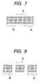
- the present invention is not limited thereto. That is, if there are no space limitations on the second large display area 3, the second large display area 3 may be made to display a six-digit figure, and two digits of the six digits may be assigned to the overall temperature display area 3c, as shown in Figs 7 and 8.
- the gap between the driver seat side temperature display area 3a and the overall temperature display area 3c and the gap between the front passenger seat side temperature display area 3b and the overall temperature display area 3c may be equal to the gap between figures as shown in Fig. 7, or may be larger than the gap between figures as shown in Fig. 8.
- the first set value related to the individual control for the driver seat side temperature and the second set value related to the individual control for the front passenger seat side temperature are displayed in the display device provided in the operating device 20 for operating a vehicle air conditioner, but the present invention is not limited thereto. That is, when the present invention is applied to a vehicle air conditioner capable of individually controlling the temperature around a rear passenger seat located at the rear side of the driver seat or the front passenger seat, temperature display areas for displaying set values related to the individual control for the respective seats may be arranged in the display device similar to the arrangement of the seats, and an overall temperature display area for displaying a set value related to the overall control may be arranged at the center of these temperature display areas.
- a set value of the temperature around the respective seats on the driver seat side may be a first set value
- a set value of the temperature around the respective seats on the front passenger seat side may be a second set value.
- a vehicle air conditioner is used as an object of application of the present embodiment, and three set values, that is, the first set value related to the individual control for the driver seat side temperature, the second set value related to the individual control for the front passenger seat side temperature, and the third set value related to the overall control are displayed in the operating device 20 of the vehicle air conditioner.
- the present invention is not limited thereto. That is, the present invention can be applied to air conditioning equipment in a building in which three or more set values related to the individual control are displayed in a display unit.
- the third set value related to the overall control may be displayed between two adjacent set values. In this case, the two adjacent set values are the first set value and the second set value, respectively.
Applications Claiming Priority (2)
| Application Number | Priority Date | Filing Date | Title |
|---|---|---|---|
| JP2003314094A JP4212995B2 (ja) | 2003-09-05 | 2003-09-05 | 表示装置 |
| JP2003314094 | 2003-09-05 |
Publications (3)
| Publication Number | Publication Date |
|---|---|
| EP1512563A2 true EP1512563A2 (de) | 2005-03-09 |
| EP1512563A3 EP1512563A3 (de) | 2005-12-07 |
| EP1512563B1 EP1512563B1 (de) | 2007-12-12 |
Family
ID=34131901
Family Applications (1)
| Application Number | Title | Priority Date | Filing Date |
|---|---|---|---|
| EP20040020882 Expired - Fee Related EP1512563B1 (de) | 2003-09-05 | 2004-09-02 | Anzeigevorrichtung |
Country Status (3)
| Country | Link |
|---|---|
| EP (1) | EP1512563B1 (de) |
| JP (1) | JP4212995B2 (de) |
| DE (1) | DE602004010584T2 (de) |
Cited By (1)
| Publication number | Priority date | Publication date | Assignee | Title |
|---|---|---|---|---|
| EP1953028A2 (de) | 2007-02-01 | 2008-08-06 | Volkswagen Aktiengesellschaft | Anzeige- und Bedienvorrichtung eines Kraftfahrzeuges mit einer Erfassung von nutzerabhängigen Parametern |
Families Citing this family (3)
| Publication number | Priority date | Publication date | Assignee | Title |
|---|---|---|---|---|
| KR101520325B1 (ko) * | 2009-02-19 | 2015-05-14 | 한라비스테온공조 주식회사 | 차량 공조장치용 컨트롤러 |
| KR101548150B1 (ko) | 2009-12-04 | 2015-08-28 | 한온시스템 주식회사 | 차량용 공조장치의 콘트롤러 |
| DE102012008208A1 (de) * | 2012-04-21 | 2013-10-24 | Volkswagen Aktiengesellschaft | Klimatisierungssystem für ein Kraftfahrzeug und Verfahren zu dessen Steuerung |
Citations (1)
| Publication number | Priority date | Publication date | Assignee | Title |
|---|---|---|---|---|
| JP2003175717A (ja) | 2001-12-10 | 2003-06-24 | Denso Corp | 車両用空調装置 |
Family Cites Families (7)
| Publication number | Priority date | Publication date | Assignee | Title |
|---|---|---|---|---|
| FR2376601A7 (fr) * | 1976-12-30 | 1978-07-28 | Meoni Dino | Horloge calendrier a plusieurs cadrans indicateurs numeriques |
| JPS621614A (ja) * | 1985-06-26 | 1987-01-07 | Nippon Denso Co Ltd | カ−エアコン制御装置 |
| JPH0242314A (ja) * | 1988-08-02 | 1990-02-13 | Sanshin Ind Co Ltd | 魚群探知機用表示システム |
| DE4023554A1 (de) * | 1990-07-25 | 1992-02-06 | Daimler Benz Ag | Verfahren zur regelung und steuerung einer klimaanlage und -automatik fuer kraftfahrzeuge |
| DE19636210C1 (de) * | 1996-09-06 | 1997-07-17 | Daimler Benz Ag | Fahrzeugklimaanlage mit Luftmengeneinstellung |
| DE19704253C2 (de) * | 1997-02-05 | 2000-01-20 | Hella Kg Hueck & Co | Bedieneinheit für eine Kfz-Komponente, insbesondere für das Steuergerät einer Kfz-Klimaanlage |
| SE511642C2 (sv) * | 1998-12-03 | 1999-11-01 | Uwe Verken Ab | Anordning vid en styrenhet |
-
2003
- 2003-09-05 JP JP2003314094A patent/JP4212995B2/ja not_active Expired - Fee Related
-
2004
- 2004-09-02 DE DE200460010584 patent/DE602004010584T2/de active Active
- 2004-09-02 EP EP20040020882 patent/EP1512563B1/de not_active Expired - Fee Related
Patent Citations (1)
| Publication number | Priority date | Publication date | Assignee | Title |
|---|---|---|---|---|
| JP2003175717A (ja) | 2001-12-10 | 2003-06-24 | Denso Corp | 車両用空調装置 |
Cited By (2)
| Publication number | Priority date | Publication date | Assignee | Title |
|---|---|---|---|---|
| EP1953028A2 (de) | 2007-02-01 | 2008-08-06 | Volkswagen Aktiengesellschaft | Anzeige- und Bedienvorrichtung eines Kraftfahrzeuges mit einer Erfassung von nutzerabhängigen Parametern |
| DE102007004923A1 (de) | 2007-02-01 | 2008-08-21 | Volkswagen Ag | Anzeige- und Bedienvorrichtung eines Kraftfahrzeugs zum Erfassen von nutzerabhängigen Parametern |
Also Published As
| Publication number | Publication date |
|---|---|
| DE602004010584D1 (de) | 2008-01-24 |
| JP4212995B2 (ja) | 2009-01-21 |
| JP2005081903A (ja) | 2005-03-31 |
| EP1512563B1 (de) | 2007-12-12 |
| EP1512563A3 (de) | 2005-12-07 |
| DE602004010584T2 (de) | 2008-12-04 |
Similar Documents
| Publication | Publication Date | Title |
|---|---|---|
| JP3411298B2 (ja) | 車両用空調装置 | |
| JP4668946B2 (ja) | 車載エアコン用操作ユニット及びそれを用いた車載エアコン制御装置 | |
| JP3398519B2 (ja) | 自動車用空気調和装置 | |
| JP5279597B2 (ja) | 車両用操作装置 | |
| US20080053128A1 (en) | Air conditioner for vehicle | |
| JP2009292293A (ja) | 車両用空調装置 | |
| JPS6061324A (ja) | 自動制御空調装置 | |
| EP1512563A2 (de) | Anzeigevorrichtung | |
| JP3232828B2 (ja) | 車両用冷房装置 | |
| JP3601886B2 (ja) | 自動車用空調システム | |
| US5746060A (en) | Air conditioner for automobile use | |
| JP2003146055A (ja) | 車両用空調装置 | |
| JPH0591920U (ja) | 自動車用空気調和装置 | |
| JPS6246370B2 (de) | ||
| JP3975873B2 (ja) | 車両用空調装置 | |
| JP3405071B2 (ja) | 車両用空調装置 | |
| JPH0848134A (ja) | 空調装置の作動表示方法 | |
| JP3788657B2 (ja) | 車両用エアコンシステムのドア制御装置 | |
| JP4238098B2 (ja) | 操作感覚付与型入力装置 | |
| JP3585304B2 (ja) | 自動車用空調システム | |
| JPH0939545A (ja) | エアコンの故障補償方法及び故障補償装置 | |
| JP2005096647A (ja) | 車載表示装置 | |
| JP4059029B2 (ja) | 車両用空調装置 | |
| JPH08324227A (ja) | 車両用空調装置 | |
| JP3059927B2 (ja) | 車両の空調制御装置 |
Legal Events
| Date | Code | Title | Description |
|---|---|---|---|
| PUAI | Public reference made under article 153(3) epc to a published international application that has entered the european phase |
Free format text: ORIGINAL CODE: 0009012 |
|
| AK | Designated contracting states |
Kind code of ref document: A2 Designated state(s): AT BE BG CH CY CZ DE DK EE ES FI FR GB GR HU IE IT LI LU MC NL PL PT RO SE SI SK TR |
|
| AX | Request for extension of the european patent |
Extension state: AL HR LT LV MK |
|
| PUAL | Search report despatched |
Free format text: ORIGINAL CODE: 0009013 |
|
| AK | Designated contracting states |
Kind code of ref document: A3 Designated state(s): AT BE BG CH CY CZ DE DK EE ES FI FR GB GR HU IE IT LI LU MC NL PL PT RO SE SI SK TR |
|
| AX | Request for extension of the european patent |
Extension state: AL HR LT LV MK |
|
| 17P | Request for examination filed |
Effective date: 20051228 |
|
| AKX | Designation fees paid |
Designated state(s): DE FR GB IT |
|
| GRAP | Despatch of communication of intention to grant a patent |
Free format text: ORIGINAL CODE: EPIDOSNIGR1 |
|
| GRAS | Grant fee paid |
Free format text: ORIGINAL CODE: EPIDOSNIGR3 |
|
| GRAA | (expected) grant |
Free format text: ORIGINAL CODE: 0009210 |
|
| AK | Designated contracting states |
Kind code of ref document: B1 Designated state(s): DE FR GB IT |
|
| REG | Reference to a national code |
Ref country code: GB Ref legal event code: FG4D |
|
| REF | Corresponds to: |
Ref document number: 602004010584 Country of ref document: DE Date of ref document: 20080124 Kind code of ref document: P |
|
| EN | Fr: translation not filed | ||
| PLBE | No opposition filed within time limit |
Free format text: ORIGINAL CODE: 0009261 |
|
| STAA | Information on the status of an ep patent application or granted ep patent |
Free format text: STATUS: NO OPPOSITION FILED WITHIN TIME LIMIT |
|
| PG25 | Lapsed in a contracting state [announced via postgrant information from national office to epo] |
Ref country code: FR Free format text: LAPSE BECAUSE OF FAILURE TO SUBMIT A TRANSLATION OF THE DESCRIPTION OR TO PAY THE FEE WITHIN THE PRESCRIBED TIME-LIMIT Effective date: 20080926 |
|
| 26N | No opposition filed |
Effective date: 20080915 |
|
| PGFP | Annual fee paid to national office [announced via postgrant information from national office to epo] |
Ref country code: IT Payment date: 20080925 Year of fee payment: 5 |
|
| GBPC | Gb: european patent ceased through non-payment of renewal fee |
Effective date: 20080902 |
|
| PG25 | Lapsed in a contracting state [announced via postgrant information from national office to epo] |
Ref country code: GB Free format text: LAPSE BECAUSE OF NON-PAYMENT OF DUE FEES Effective date: 20080902 |
|
| PG25 | Lapsed in a contracting state [announced via postgrant information from national office to epo] |
Ref country code: IT Free format text: LAPSE BECAUSE OF NON-PAYMENT OF DUE FEES Effective date: 20090902 |
|
| PGFP | Annual fee paid to national office [announced via postgrant information from national office to epo] |
Ref country code: DE Payment date: 20140930 Year of fee payment: 11 |
|
| REG | Reference to a national code |
Ref country code: DE Ref legal event code: R119 Ref document number: 602004010584 Country of ref document: DE |
|
| PG25 | Lapsed in a contracting state [announced via postgrant information from national office to epo] |
Ref country code: DE Free format text: LAPSE BECAUSE OF NON-PAYMENT OF DUE FEES Effective date: 20160401 |