EP1510336A2 - Bildaufzeichnungsgerät mit Stanzeinheit - Google Patents
Bildaufzeichnungsgerät mit Stanzeinheit Download PDFInfo
- Publication number
- EP1510336A2 EP1510336A2 EP04020049A EP04020049A EP1510336A2 EP 1510336 A2 EP1510336 A2 EP 1510336A2 EP 04020049 A EP04020049 A EP 04020049A EP 04020049 A EP04020049 A EP 04020049A EP 1510336 A2 EP1510336 A2 EP 1510336A2
- Authority
- EP
- European Patent Office
- Prior art keywords
- recording
- recording material
- drum
- peripheral surface
- recording drum
- Prior art date
- Legal status (The legal status is an assumption and is not a legal conclusion. Google has not performed a legal analysis and makes no representation as to the accuracy of the status listed.)
- Granted
Links
Images








Classifications
-
- B—PERFORMING OPERATIONS; TRANSPORTING
- B41—PRINTING; LINING MACHINES; TYPEWRITERS; STAMPS
- B41C—PROCESSES FOR THE MANUFACTURE OR REPRODUCTION OF PRINTING SURFACES
- B41C1/00—Forme preparation
- B41C1/10—Forme preparation for lithographic printing; Master sheets for transferring a lithographic image to the forme
- B41C1/1083—Mechanical aspects of off-press plate preparation
Definitions
- This invention relates to an image recording apparatus for recording an image by emitting light beams to a recording material mounted on a recording drum.
- positioning bore for the printing machine used in this specification includes a positioning bore used in placing the printing plate on a plate cylinder of the printing machine, and also a punch bore such as a positioning bore used in placing the printing plate on a puncher for forming a further punch bore in the printing plate.
- a positioning bore for positioning a recording material on a recording drum and a positioning bore for the printing machine are formed almost simultaneously in the recording material before attachment to the recording drum, and the recording material is positioned on the recording drum by using the former.
- the recording material is positioned relative to the recording drum by placing the positioning bore formed at an end of the recording material in contact with a positioning pin, and then the recording material is fixed to the recording drum.
- a punch unit is disposed on a surface of a recording drum, and after attaching a recording material peripherally of the recording drum, the punch unit is used to form a positioning bore for the printing machine in the recording material for use in positioning a printing plate.
- the recording material is positioned on the recording drum by placing the positioning bore formed at an end of the recording material in contact with positioning pin.
- This method has a drawback that, where the recording material is a soft material, a deformation of the recording material makes it impossible to position the recording material accurately on the recording drum. This results in an inaccurate positional relationship between the positioning bore and a recorded image.
- the second method described above requires the punch unit to be attached peripherally of the recording drum.
- the weight of the punch unit will make it difficult to rotate the recording drum with high accuracy unless the weight balance of the entire recording drum is adjusted accurately.
- the punch unit is customized, it is necessary to perform an adjustment of the weight balance of the recording drum again, and hence a drawback of the punch unit not being easy to customize.
- the object of this invention is to provide an image recording apparatus capable of accurately maintaining a positional relationship between an image recorded on a recording material and a positioning bore, and enabling a simple balance adjustment of a recording drum.
- an image recording apparatus comprising:
- the accuracy of the positional relationship between a punch bore formed by the punch unit and a recorded image may be improved without positioning the recording material on the peripheral surface of the recording drum with high precision.
- the punch unit need not be attached to the recording drum since the moving mechanism is provided for moving the punch unit between a standby position separated from the recording drum and a punching position. Thus, there is no need to adjust the weight balance of the recording drum when customizing the punch unit.
- the apparatus further comprises a sensor for detecting a position of the forward end of the recording material mounted peripherally of the recording drum.
- the apparatus may further comprise suction bores formed in the peripheral surface of the recording drum, and an exhaust mechanism connected to the suction bores through an air duct for drawing air through the air duct, thereby holding the recording material on the peripheral surface of the recording drum by suction.
- the exhaust mechanism When discharging the recording material from the peripheral surface of the recording drum, the exhaust mechanism may be reversed to feed air into the air duct.
- the apparatus may further comprise a craw mechanism for separating the recording material from the peripheral surface of the recording drum when discharging the recording material from the peripheral surface of the recording drum.
- the apparatus further comprise a sensor for detecting a position of the forward end of the recording material mounted peripherally of the recording drum, and a control device for controlling an amount of movement of the punch unit caused by the moving mechanism according to the position of the forward end of the recording material detected by the sensor, and adjusting an image recording start position of the recording head based on the position of the forward end of the recording material detected by the sensor.
- the sensor may be attached to the punch unit for detecting the position of the forward end of the recording material during movement of the punch unit.
- FIG. 1 is a schematic view of an image recording apparatus according to this invention.
- the image recording apparatus includes two recording material storage sections 12 arranged vertically, a recording material transport device 13 used for transporting a recording material P, a lift mechanism for raising and lowering the transport device 13, a tilt mechanism having a cam 52 and a cam follower 53 for tilting the transport device 13, a recording drum 14 for supporting the recording material P mounted peripherally thereof, an image recorder 15 for recording an image on the recording material P mounted on the recording drum 14, and a discharge mechanism 17 for discharging the recording material P having the image recorded thereon to a discharge tray 16.
- Each of the recording material storage sections 12 includes a magazine 21 storing an elongate recording material P in roll form therein, and a pair of take-out rollers 23 and 24 for taking the recording material P out of the magazine 21.
- the recording material transport device 13 supports, in a horizontal state, the recording material P drawn from either recording material storage section 12, and transports the recording material P toward the recording drum 14 in a switchback mode.
- the transport device 13 includes a pair of transport rollers 31 and 32 for transporting the recording material P, and a cutter 22 for cutting the elongate recording material P.
- This recording material transport device 13 is movable, by action of the lift mechanism and tilt mechanism, between a position, referenced A in Fig. 1, opposed to the upper recording material storage section 12, a position referenced B opposed to the lower recording material storage section 12, and a position referenced C opposed to the recording drum 14.
- the image recorder 15 for recording an image on the recording material P mounted on the recording drum 14 includes a recording head 65, and a moving mechanism for moving the recording head 65 axially of the recording drum 14 (in a direction perpendicular to the plane of Fig. 1: secondary scanning direction). With the recording drum 14 rotated at high speed in a primary scanning direction and the recording head 65 moved axially of the recording drum 14, the image recorder 15 records an image by emitting laser beams, for example, to the recording material P.
- the recording head 65 is moved in the secondary scanning direction by a motor, not shown, synchronously with the rotation of the recording drum 14.
- the recording head 65 emits laser beams to the recording material P with the rotation of the recording drum 14, in accordance with primary scan position information received from an encoder 131, described hereinafter, and indicating rotation angles of the recording drum 14.
- the image recorder 15 can record on the recording material P an image having position reproducibility in relation to the peripheral surface of the recording drum 14.
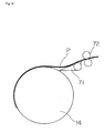
- the discharge mechanism 17 for discharging the recording material P after an image recording step to the discharge tray 16 includes claws 71 for separating the recording material P from the peripheral surface of the recording drum 14, a plurality of transport roller pairs 72 and a direction change member 74.
- the direction change member 74 has a transport roller pair 73 disposed at one end thereof, and is movable from a position shown in solid lines to a position shown in two-dot chain lines in Fig. 1, thereby changing the moving direction of the recording material P in a switchback mode.
- the discharge mechanism 17 removes the recording material P with an image recorded thereon from the peripheral surface of the recording drum 14 and transports the recording material P to the discharge tray 16.
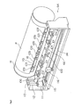
- FIGS. 2 and 3 are perspective views showing the punch mechanism 64 along with the recording drum 14.
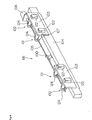
- Fig. 4 is a perspective view showing a punch unit 66 in the punch mechanism 64 seen in a direction reversed from Figs. 2 and 3.
- This punch mechanism 64 includes the punch unit 66, and a moving mechanism for vertically moving the punch unit 66 between a standby position shown in Fig. 2 and a punching position shown in Fig. 3.
- the punch unit 66 has a pair of punch blocks 101 for forming positioning bores in a recording material P of relatively small size, and a pair of punch blocks 102 for forming positioning bores in a recording material P of relatively large size. These punch blocks 101 and 102 are supported by an arm 104 through support plates 103.
- the arm 104 has a motor 106 for rotating a drive rod 105 to drive the punch blocks 101 and 102, a detector 100 for detecting rotation angles of the drive rod 105, and a sensor 107 for detecting the forward end of recording material P.
- the moving mechanism includes support members 111 arranged at opposite ends of the arm 104, slide shafts 112 and ball screws 113 connected to the support members 111, and a pulse motor 116 for driving the ball screws 113 through a synchronous belt 114 and synchronous pulleys 115.
- the ball screws 113 rotated by drive of the pulse motor 116 vertically move the punch unit 66 between the standby position shown in Fig. 2 and the punching position shown in Fig. 3.
- the punching position of the punch unit 66 is a position where the forward end of the recording material P mounted peripherally of the recording drum 14 is inserted into slits 121 formed in dies 122 of the respective punch blocks 101 and 102 as described hereinafter.
- the standby position is a position where the punch unit 66 is lowered from the punching position away from the recording drum 14.
- Fig. 15 is an enlarged perspective view of a portion of the recording drum 14 for illustrating a recess 18. For simplicity of illustration, certain components such as forward end clamps 109 are omitted from this figure.
- the recess 18 is a groove of airfoil section having a depth increasing gradually in a circumferential direction, and elongated axially of the recording drum 14.
- a plurality of projections 18a are formed at intervals axially of the recording drum 14 for arranging the forward end clamps 109.
- the surfaces of projections 18a have the same curvature as the peripheral surface of the recording drum 14.
- the recording material P is fed in the X-direction in Fig. 15, with the forward end stopping in a position on the projections 18a indicated by an alternate long and short dash line y.
- the recording material P is supported in an intermediate portion thereof by the plurality of projections 18a, and is fixed in this state by the forward end clamps 109 described hereinafter. Consequently, the forward end of the recording material P does not sink into the recess 18. That is, the forward end of the recording material P is supported linearly over the recess 18.
- Punches 123 of the punch blocks 101 and 102 are retractably movable in the Y-direction in Fig. 15 into cutout portions arranged laterally of the projections 18a.
- the recording drum 14 has six forward end clamps 109 for clamping the forward end of the recording material P disposed over the recess 18 in the recording drum 14.
- the forward end clamps 109 are opened and closed by the opening and closing mechanism 61 noted hereinbefore.
- a windshield bar 110 is disposed adjacent these forward end clamps 109.
- the forward end clamps 109 are hinge-shaped elements each having an end for pressing and fixing the recording material P. This end is biased toward the peripheral surface of the recording drum 65 by a spring not shown. The forward end clamps 109 are opened when the other ends are pressed by the opening and closing mechanism 61, to be ready for receiving the forward end of the recording material P fed by the recording material transport device 13.
- the windshield bar 110 is a plate-like element elongated axially of the recording drum 14 with a plurality of (e.g. six) cutout portions formed in positions corresponding to the forward end clamps 109.
- the windshield bar 110 is secured to the bottom of the recess 18 to have an open/close end thereof facing the same direction as the ends of the forward end clamps 109 that press the recording material P.
- the windshield bar 110 is biased by a spring 110a in a direction to open the open/close end thereof.
- the windshield bar 110 with the open/close end thereof opened, prevents airflows entering between the forward end of the recording material P and the recording drum 65.
- Fig. 5 is an explanatory view showing a principal part of the punch block 101 (102).
- Figs. 6 and 7 are explanatory views showing an operation of the punch blocks 101 and 102 for forming positioning bores.
- Each of the punch blocks 101 and 102 has a die 122 defining a slit 121, and a punch 123 movable through the die 122 for punching a positioning bore in the recording material P inserted into the slit 121.
- the punch 123 is connected to a moving member 125, movable back and forth through a case 124 (Fig. 4).
- the moving member 125 has an elliptical opening 126 formed at an end thereof.
- the opening 126 has a cam 127 mounted therein and connected to the drive rod 105 described hereinbefore.
- the cam 127 presses on the inner wall of the opening 126.
- the moving member 125 moves through the case 124.
- the punch 123 moves in the die 122 to a position for punching a positioning bore in the recording material inserted into the slit 121.
- Cams 127a in the pair of punch blocks 101 and cams 127b in the pair of punch blocks 102 are connected in different phases to the drive rod 105.
- the punch 123 in each punch block 102 moves to the position for punching a positioning bore in the recording material as shown in Figs. 6A and 7A.
- the punch 123 in each punch block 101 moves to the position for punching a positioning bore in the recording material as shown in Figs. 6C and 7C.
- positioning bores may be formed with different distances therebetween by changing the directions of rotation of the drive rod 125.
- the construction of the punch unit 66 may be made simple.
- FIG. 8 is a block diagram showing the principal electrical structure of the image recording apparatus.
- the recording drum 14 for supporting the recording material P is connected to a motor 130.
- the encoder 131 noted hereinbefore is attached to the motor 130.
- the encoder 131 transmits primary scan position information indicating a rotation angle of the recording drum 14 to a controller 140.
- the recording head 65 Based on the primary scan position information received from the encoder 131 and image data received from an image memory 136, the recording head 65 emits modulated laser beams to the recording material P mounted peripherally of the recording drum 14. Further, the recording head 65 receives from the controller 140 data for changing an image recording start position described hereinafter.
- the controller 140 is connected also to the motor 106 for rotating the drive rod 105 of the punch unit 66, the sensor 107 for detecting the forward end of the recording material P, and the pulse motor 116 for vertically moving the punch unit 66.
- the recording drum 14 has a hollow configuration.
- the recording drum 14 has suction bores formed in the peripheral surface thereof and communicating with an inner space of the drum 14 for holding by suction the recording material P on the peripheral surface of the drum 14.
- the inner space of the recording drum 14 is connected through an air duct 133 to a blower 134 driven by an inverter 135. By drawing air from the duct 133 by action of the blower 134, the recording material P can be suction-supported on the peripheral surface of the recording drum 14.
- This blower 134 is reversible by controlling the inverter 135 with a signal from the controller 140. As described hereinafter, when discharging the recording material P from the peripheral surface of the recording drum 14, the blower 134 is reversed to feed air into the inner space of the recording drum 14.
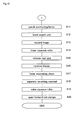
- FIGs. 9 and 10 are flow charts of the operations from attaching the recording material P to the recording drum 14 to discharging the recording material P.
- step S1 the forward end of the recording material P fed from the recording material transport device 13 in the position C in Fig. 1 is clamped to the peripheral surface of the recording drum 14 (step S1). This operation is performed by causing the opening and closing mechanism 61 shown in Fig. 1 to operate the forward end clamps 109 shown in Figs. 2 and 3.
- the inverter 135 shown in Fig. 8 causes the blower 134 to rotate forward (step S2). Then, the squeeze roller 63 shown in Fig. 1 is lowered to the recording material P (step S3). The recording drum 14 is rotated at low speed counterclockwise in Fig. 1, to wrap the recording material P close around the peripheral surface of the recording drum 14 (step S4).
- step S5 the rear end of the recording material P is clamped.
- This operation is performed by causing the opening and closing mechanism 62 shown in Fig. 1 to attach the rear end clamps to the peripheral surface of the recording drum 14.
- the squeeze roller 63 is raised (Step S6).
- the recording drum 14 is rotated to a punching standby position and stopped in this angular position (step S7).
- the controller 140 constantly supervises angular positions of the recording drum 14 based on the signals from the encoder 131, and can stop the recording drum 14 in an exact position relative to the punch unit 66. After the recording drum 14 is rotated to the punching standby position, a further rotation of the recording drum 14 may be mechanically prohibited by a braking mechanism.
- the pulse motor 116 shown in Figs. 2 and 3 is operated to raise the punch unit 66 (step S8).
- the sensor 107 attached to the punch unit 66 checks for the forward end of the recording material P.
- the punch unit 66 is determined to lie in the punching position, and the ascent of the punch unit 66 is stopped (step S10).
- the punch unit 66 may be stopped at a point of time when the punch unit 66 has been raised by a fixed amount after the sensor 107 detects the forward end of the recording material P. In this case also, the forward end of the recording material P and the punch unit 66 may be placed in a fixed positional relationship at all times.
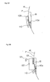
- the windshield bar 110 noted hereinbefore is disposed in a position adjacent the forward end of the recording material P.
- the punch unit 66 is moved to the punching position, as shown in Fig. 12B, the windshield bar 110 is pressed by the dies 122 into the recess 18.
- the windshield bar 110 returns to the position shown in Fig. 12A.
- the motor 106 of the punch unit 66 is operated to rotate the drive rod 105 in either direction, to move the punches 123 in the dies 122 of the punch blocks 101 or 102, thereby punching positioning bores in the recording material P inserted into the slits 121 (step S11).
- the punch unit 66 is lowered to the standby position (step S12).
- the recording drum 14 is rotated at high speed for recording an image (step S13).
- an adjustment is made of an image recording start position in the primary scanning direction based on the position of the forward end of the recording material P detected by the sensor 107.
- Fig. 13 is an explanatory view showing positions of a positioning bore 201 and image recording start positions.
- the forward end of the recording material P may coincide with a reference position on the peripheral surface of the recording drum 14. Then, the recording start position for image 200 coincides with a predetermined position, and an plate edge distance (i.e. a distance from the forward end of the recording material P to the center of the positioning bore 201) is L1 at this time.
- the embodiment described above constantly secures the plate edge distance L1 by stopping the ascent of the punch unit 66 by the pulse motor 116 when the sensor 107 detects the forward end of the recording material P.
- the image recording start position in the primary scanning direction is adjusted according to the position of the forward end of the recording material P detected by the sensor 107, thereby fixing the positional relationship between the positioning bore 201 and the image 200.
- step S14 when the image recording operation is completed, the squeeze roller 63 is lowered to the recording material P (step S14). Then, the clamped rear end of the recording material P is released (step S15).
- the blower 134 is reversed by action of the inverter 135 shown in Fig. 8, to feed air into the inner space of the recording drum 14 through the duct 133 (step S16). This will facilitate separation of the recording material P from the peripheral surface of the recording drum 14.
- the separating claws 71 are lowered to a position for contacting the surface of the recording drum 14 (step S17). Then, the recording drum 14 is rotated clockwise in Fig. 1, to separate the recording material P from the peripheral surface of the recording drum 14 (step S18). In this state, as shown in Fig. 14, the recording material P is guided at the forward end thereof by the separating claws 71 to one of the transport roller pairs 72. Then, the squeeze roller 63 is raised (step S19), the clamped forward end of the recording material P is released (step S20), and the recording material P is transported toward the discharge mechanism 17.
- the recording material P is held on the peripheral surface of the recording drum 14 by the combination of clamps and vacuum suction.
- the recording material P may be held in place only by the clamps or by vacuum suction of the blower 134.
- this invention may be implemented also where the recording material P is held on the peripheral surface of the recording drum 14 by an attaching mechanism other than the clamps or vacuum suction.
- the sensor 107 is attached to the punch unit 66, the punch unit 66 is raised by the pulse motor 116 toward the recording drum 65 in the punching standby position, and when the sensor 107 detects the forward end of the recording material P, the ascent of the punch unit 66 is stopped. Then, the image recording start position is adjusted according to the amount of ascent from the standby position (initial position) of the punch unit 66. By performing a punching operation in this way, the positioning bore and recorded image may be maintained in a desired positional relationship while securing a fixed plate edge distance.
- the above punching process is not absolutely necessary. That is, the sensor 107 is dispensable.
- a process carried out in this case will be described with reference to the flow charts of Figs. 9 and 10.
- the punch unit 66 is raised a fixed amount in step S8 of Fig. 9.
- the detection of the forward end of the recording material P by the sensor 107 is not carried out. Since the recording drum 14 is already located in the exact punching standby position in step S7, positioning bores may be formed in a fixed position relative to the peripheral surface of the recording drum 14, without the detection of the forward end of the recording material P, only by setting a fixed amount of ascent of the punch unit 66.
- the forward end of the recording material P1 may be fixed as displaced from the reference position on the peripheral surface of the recording drum 14.
- the punch unit 66 may be raised by the same amount as where the recording material P2 is fixed to the reference position (in the left side in Fig. 16), whereby the same positional relationship between the positioning bore 201 and recorded image 200 is secured for the two recording materials P1 and P2.
- the displacement circumferentially of the recording drum 14 between the punch bore 201 and the upper right end of the recorded image is L3 for both recording materials P1 and P2.
- the sensor 107 is used for correcting the recording start position and punching position for the recording material P.
- the sensor 107 may be used to perform error handling such as giving a warning to the operator after detecting a displacement from the reference position of the recording material P attached. In this case, whether a displacement from the reference position of the recording material P as fixed is in a permissible range or not is determined from whether an amount of ascent from the standby position of the punch unit 66 until the sensor 107 detects the forward end of the recording material P is within a predetermined range or not. When the amount of ascent is outside the above predetermined range, an error process is carried out by displaying an error message or discharging the recording material P fixed to the recording drum 14 from the apparatus without performing an image recording operation.
- a displacement of the recording material P in the primary scanning direction is detected.
- a displacement of the recording material P in the secondary scanning direction may be detected.
- the punch unit 66 is moved in the secondary scanning direction, and the image recording start position of the recording head 65 also is moved in the secondary scanning direction.
- an amount of inclination of the recording material P may be detected by a plurality of sensors 107 attached at different heights to the punch unit 66.
- the punching timing of each punch block 101 (102) forming the pair of punch blocks 101 (102) is varied from that of the other. That is, after one of the two punch blocks 101 (102) punches a bore, the punch unit 66 is raised by an amount corresponding to the above amount of inclination, and is moved in the secondary scanning direction. Then, the other punch block 101 (102) punches a bore.
- a straight line linking the pair of positioning bores 201 formed by the pair of punch blocks 101 (102) runs parallel to the forward end of the recording material P.
- the image data stored in the image memory 136 is rotated, thereby to rotate an image recorded by the recording head 65 on the recording material P.
Landscapes
- Engineering & Computer Science (AREA)
- Mechanical Engineering (AREA)
- Manufacturing & Machinery (AREA)
- Exposure And Positioning Against Photoresist Photosensitive Materials (AREA)
- Moulds For Moulding Plastics Or The Like (AREA)
- Perforating, Stamping-Out Or Severing By Means Other Than Cutting (AREA)
- Manufacture Or Reproduction Of Printing Formes (AREA)
Applications Claiming Priority (2)
| Application Number | Priority Date | Filing Date | Title |
|---|---|---|---|
| JP2003304288A JP4307935B2 (ja) | 2003-08-28 | 2003-08-28 | 画像記録装置 |
| JP2003304288 | 2003-08-28 |
Publications (3)
| Publication Number | Publication Date |
|---|---|
| EP1510336A2 true EP1510336A2 (de) | 2005-03-02 |
| EP1510336A3 EP1510336A3 (de) | 2005-12-14 |
| EP1510336B1 EP1510336B1 (de) | 2007-03-28 |
Family
ID=34101213
Family Applications (1)
| Application Number | Title | Priority Date | Filing Date |
|---|---|---|---|
| EP04020049A Expired - Lifetime EP1510336B1 (de) | 2003-08-28 | 2004-08-24 | Bildaufzeichnungsgerät mit Stanzeinheit |
Country Status (5)
| Country | Link |
|---|---|
| US (1) | US7073441B2 (de) |
| EP (1) | EP1510336B1 (de) |
| JP (1) | JP4307935B2 (de) |
| CN (1) | CN100410812C (de) |
| DE (1) | DE602004005541T2 (de) |
Cited By (3)
| Publication number | Priority date | Publication date | Assignee | Title |
|---|---|---|---|---|
| WO2007117477A3 (en) * | 2006-04-03 | 2008-03-13 | Eastman Kodak Co | Plate processing system and method |
| CN104608467A (zh) * | 2014-12-05 | 2015-05-13 | 丹东金丸集团有限公司 | 纳米直接制版机中打印头与滚筒同步控制系统及方法 |
| CN110346446A (zh) * | 2019-07-31 | 2019-10-18 | 中国石油大学(北京) | 无损检测装置 |
Families Citing this family (5)
| Publication number | Priority date | Publication date | Assignee | Title |
|---|---|---|---|---|
| JP4573567B2 (ja) * | 2004-04-27 | 2010-11-04 | 大日本スクリーン製造株式会社 | 画像記録装置 |
| US20070227385A1 (en) * | 2006-04-03 | 2007-10-04 | Mcgaire Mark D | Punching debris extraction system |
| US7641332B2 (en) * | 2006-04-03 | 2010-01-05 | Eastman Kodak Company | Post-imaging punching apparatus and method |
| US20070227384A1 (en) * | 2006-04-03 | 2007-10-04 | Mcgaire Mark D | Imaging and punching thermal control system |
| CN104494281B (zh) * | 2014-12-05 | 2017-08-18 | 丹东金丸集团有限公司 | 纳米直接制版机自动换板方法 |
Family Cites Families (17)
| Publication number | Priority date | Publication date | Assignee | Title |
|---|---|---|---|---|
| SE442964B (sv) * | 1982-12-01 | 1986-02-10 | Tetra Pak Int | Sett att avlegsna spillmaterial vid stansaggregat med samverkande valsar |
| US4840121A (en) * | 1986-11-26 | 1989-06-20 | Am International, Inc. | Master holding mechanism for duplicating machines |
| DE4226780C2 (de) * | 1992-08-13 | 1994-12-01 | Roland Man Druckmasch | Vorrichtung zur Kontrolle der registergerechten Anlage einer Druckplatte auf dem Plattenzylinder von Druckmaschinen, insbesondere Bogenoffsetdruckmaschinen |
| JP2895735B2 (ja) | 1994-02-14 | 1999-05-24 | 大日本スクリーン製造株式会社 | 円筒内面走査装置 |
| JPH0839491A (ja) * | 1994-07-28 | 1996-02-13 | Dainippon Screen Mfg Co Ltd | 画像記録装置用パンチ装置 |
| DE19507870A1 (de) * | 1995-03-08 | 1996-09-12 | Hell Ag Linotype | Stanzmodul für Druckplattenbelichter |
| JPH0999620A (ja) * | 1995-07-31 | 1997-04-15 | Tohoku Ricoh Co Ltd | 製版装置およびそれに用いる製版用マスタ |
| JP3396358B2 (ja) | 1995-11-30 | 2003-04-14 | 大日本スクリーン製造株式会社 | 画像記録装置の回転ドラム |
| JP4009351B2 (ja) * | 1997-08-11 | 2007-11-14 | 大日本スクリーン製造株式会社 | 画像出力装置 |
| EP0902586B1 (de) * | 1997-09-10 | 2005-11-16 | Kabushiki Kaisha Toshiba | Lichtstrahlabtast- und Bilderzeugungsgerät |
| JP3708716B2 (ja) | 1998-08-04 | 2005-10-19 | 大日本スクリーン製造株式会社 | 描画装置 |
| US6321651B1 (en) * | 2000-02-25 | 2001-11-27 | Agfa Corporation | Pin registration system for mounting different width printing plates |
| DE10015728A1 (de) * | 2000-03-29 | 2001-10-04 | Koenig & Bauer Ag | Vorrichtung zum registergerechten Aufspannen einer Druckplatte |
| ATE478361T1 (de) * | 2001-05-11 | 2010-09-15 | Dainippon Screen Mfg | Abtastgerät für eine zylindrische aussenfläche |
| JP4185269B2 (ja) * | 2001-08-23 | 2008-11-26 | 富士フイルム株式会社 | シート材保持方法及び画像記録装置 |
| JP3977643B2 (ja) * | 2002-01-07 | 2007-09-19 | 大日本スクリーン製造株式会社 | 画像記録装置 |
| US6772691B2 (en) * | 2002-08-29 | 2004-08-10 | Agfa Corporation | System and method for registering media in an imaging system |
-
2003
- 2003-08-28 JP JP2003304288A patent/JP4307935B2/ja not_active Expired - Fee Related
-
2004
- 2004-08-24 DE DE602004005541T patent/DE602004005541T2/de not_active Expired - Lifetime
- 2004-08-24 EP EP04020049A patent/EP1510336B1/de not_active Expired - Lifetime
- 2004-08-24 US US10/923,852 patent/US7073441B2/en not_active Expired - Lifetime
- 2004-08-26 CN CNB2004100578906A patent/CN100410812C/zh not_active Expired - Fee Related
Cited By (5)
| Publication number | Priority date | Publication date | Assignee | Title |
|---|---|---|---|---|
| WO2007117477A3 (en) * | 2006-04-03 | 2008-03-13 | Eastman Kodak Co | Plate processing system and method |
| CN104608467A (zh) * | 2014-12-05 | 2015-05-13 | 丹东金丸集团有限公司 | 纳米直接制版机中打印头与滚筒同步控制系统及方法 |
| CN104608467B (zh) * | 2014-12-05 | 2017-08-18 | 丹东金丸集团有限公司 | 纳米直接制版机中打印头与滚筒同步控制方法 |
| CN110346446A (zh) * | 2019-07-31 | 2019-10-18 | 中国石油大学(北京) | 无损检测装置 |
| CN110346446B (zh) * | 2019-07-31 | 2024-05-10 | 中国石油大学(北京) | 无损检测装置 |
Also Published As
| Publication number | Publication date |
|---|---|
| US7073441B2 (en) | 2006-07-11 |
| DE602004005541T2 (de) | 2007-12-06 |
| CN100410812C (zh) | 2008-08-13 |
| JP2005077456A (ja) | 2005-03-24 |
| EP1510336B1 (de) | 2007-03-28 |
| EP1510336A3 (de) | 2005-12-14 |
| DE602004005541D1 (de) | 2007-05-10 |
| CN1591201A (zh) | 2005-03-09 |
| JP4307935B2 (ja) | 2009-08-05 |
| US20050056168A1 (en) | 2005-03-17 |
Similar Documents
| Publication | Publication Date | Title |
|---|---|---|
| EP2129524B1 (de) | Druckplattenregistrierung mit einer kamera | |
| EP1510336B1 (de) | Bildaufzeichnungsgerät mit Stanzeinheit | |
| US6097475A (en) | Method and apparatus for orienting a recording media sheet on a support surface | |
| EP0944235A2 (de) | Bilderzeugungssystem mit integrierter Stanzvorrichtung | |
| US5987949A (en) | Plate scanner--bending device | |
| US6792861B2 (en) | Image recorder with recording material feed unit | |
| EP1394614B1 (de) | System zur Registrierung von Medien in einem Bilderzeugungssystem | |
| US7146911B2 (en) | Image recorder | |
| JPH07226827A (ja) | 円筒内面走査装置 | |
| US6889976B2 (en) | Image recorder | |
| EP1395037A2 (de) | System und Methode zur Kalibrierung eines Bilderzeugungssystems während der Bildaufnahme | |
| JPH0588379A (ja) | 感光材料焼付装置 | |
| US7088384B2 (en) | Image recorder for punching hole by movable punching element | |
| JP4040145B2 (ja) | 露光装置 | |
| JP2004294530A (ja) | 穿孔及び画像露光システム | |
| JPH0862821A (ja) | 画像記録装置 | |
| JP4040146B2 (ja) | 露光装置 | |
| JP3705543B2 (ja) | 円筒外面走査装置 | |
| JP3656959B2 (ja) | 円筒外面走査装置及び刷版サイズチェック方法 | |
| US6470777B2 (en) | Low profile side punch for internal drum imagesetter | |
| JP2984815B2 (ja) | プリンタの自動用紙厚調整機構 | |
| JP2003091080A (ja) | 画像記録装置 | |
| JP2005316115A (ja) | 画像記録装置、切り欠き形成装置、およびその方法 | |
| JP2001080787A (ja) | 搬送ユニットの調整方法及び搬送ユニットの調整治具 | |
| JP2002341556A (ja) | 円筒外面走査装置 |
Legal Events
| Date | Code | Title | Description |
|---|---|---|---|
| PUAI | Public reference made under article 153(3) epc to a published international application that has entered the european phase |
Free format text: ORIGINAL CODE: 0009012 |
|
| AK | Designated contracting states |
Kind code of ref document: A2 Designated state(s): AT BE BG CH CY CZ DE DK EE ES FI FR GB GR HU IE IT LI LU MC NL PL PT RO SE SI SK TR |
|
| AX | Request for extension of the european patent |
Extension state: AL HR LT LV MK |
|
| PUAL | Search report despatched |
Free format text: ORIGINAL CODE: 0009013 |
|
| AK | Designated contracting states |
Kind code of ref document: A3 Designated state(s): AT BE BG CH CY CZ DE DK EE ES FI FR GB GR HU IE IT LI LU MC NL PL PT RO SE SI SK TR |
|
| AX | Request for extension of the european patent |
Extension state: AL HR LT LV MK |
|
| 17P | Request for examination filed |
Effective date: 20060314 |
|
| AKX | Designation fees paid |
Designated state(s): DE FR GB |
|
| GRAP | Despatch of communication of intention to grant a patent |
Free format text: ORIGINAL CODE: EPIDOSNIGR1 |
|
| GRAS | Grant fee paid |
Free format text: ORIGINAL CODE: EPIDOSNIGR3 |
|
| GRAA | (expected) grant |
Free format text: ORIGINAL CODE: 0009210 |
|
| AK | Designated contracting states |
Kind code of ref document: B1 Designated state(s): DE FR GB |
|
| REG | Reference to a national code |
Ref country code: GB Ref legal event code: FG4D |
|
| REF | Corresponds to: |
Ref document number: 602004005541 Country of ref document: DE Date of ref document: 20070510 Kind code of ref document: P |
|
| ET | Fr: translation filed | ||
| PLBE | No opposition filed within time limit |
Free format text: ORIGINAL CODE: 0009261 |
|
| STAA | Information on the status of an ep patent application or granted ep patent |
Free format text: STATUS: NO OPPOSITION FILED WITHIN TIME LIMIT |
|
| 26N | No opposition filed |
Effective date: 20080102 |
|
| REG | Reference to a national code |
Ref country code: DE Ref legal event code: R082 Ref document number: 602004005541 Country of ref document: DE Representative=s name: KILIAN KILIAN & PARTNER, DE |
|
| REG | Reference to a national code |
Ref country code: DE Ref legal event code: R082 Ref document number: 602004005541 Country of ref document: DE Representative=s name: KILIAN KILIAN & PARTNER, DE |
|
| REG | Reference to a national code |
Ref country code: DE Ref legal event code: R082 Ref document number: 602004005541 Country of ref document: DE Representative=s name: KILIAN KILIAN & PARTNER, DE Effective date: 20130130 Ref country code: DE Ref legal event code: R082 Ref document number: 602004005541 Country of ref document: DE Representative=s name: KILIAN KILIAN & PARTNER, DE Effective date: 20150317 Ref country code: DE Ref legal event code: R081 Ref document number: 602004005541 Country of ref document: DE Owner name: SCREEN HOLDINGS CO., LTD., JP Free format text: FORMER OWNER: DAINIPPON SCREEN MFG. CO., LTD., KYOTO, JP Effective date: 20150317 Ref country code: DE Ref legal event code: R082 Ref document number: 602004005541 Country of ref document: DE Representative=s name: KILIAN KILIAN & PARTNER MBB PATENTANWAELTE, DE Effective date: 20130130 Ref country code: DE Ref legal event code: R082 Ref document number: 602004005541 Country of ref document: DE Representative=s name: KILIAN KILIAN & PARTNER MBB PATENTANWAELTE, DE Effective date: 20150317 |
|
| REG | Reference to a national code |
Ref country code: FR Ref legal event code: CD Owner name: SCREEN HOLDINGS CO., LTD. Effective date: 20150622 |
|
| REG | Reference to a national code |
Ref country code: FR Ref legal event code: PLFP Year of fee payment: 13 |
|
| REG | Reference to a national code |
Ref country code: FR Ref legal event code: PLFP Year of fee payment: 14 |
|
| REG | Reference to a national code |
Ref country code: FR Ref legal event code: PLFP Year of fee payment: 15 |
|
| PGFP | Annual fee paid to national office [announced via postgrant information from national office to epo] |
Ref country code: DE Payment date: 20190813 Year of fee payment: 16 Ref country code: FR Payment date: 20190711 Year of fee payment: 16 |
|
| PGFP | Annual fee paid to national office [announced via postgrant information from national office to epo] |
Ref country code: GB Payment date: 20190822 Year of fee payment: 16 |
|
| REG | Reference to a national code |
Ref country code: DE Ref legal event code: R119 Ref document number: 602004005541 Country of ref document: DE |
|
| GBPC | Gb: european patent ceased through non-payment of renewal fee |
Effective date: 20200824 |
|
| PG25 | Lapsed in a contracting state [announced via postgrant information from national office to epo] |
Ref country code: FR Free format text: LAPSE BECAUSE OF NON-PAYMENT OF DUE FEES Effective date: 20200831 Ref country code: DE Free format text: LAPSE BECAUSE OF NON-PAYMENT OF DUE FEES Effective date: 20210302 |
|
| PG25 | Lapsed in a contracting state [announced via postgrant information from national office to epo] |
Ref country code: GB Free format text: LAPSE BECAUSE OF NON-PAYMENT OF DUE FEES Effective date: 20200824 |