EP1507944B1 - Deckelsteller - Google Patents
Deckelsteller Download PDFInfo
- Publication number
- EP1507944B1 EP1507944B1 EP03735427A EP03735427A EP1507944B1 EP 1507944 B1 EP1507944 B1 EP 1507944B1 EP 03735427 A EP03735427 A EP 03735427A EP 03735427 A EP03735427 A EP 03735427A EP 1507944 B1 EP1507944 B1 EP 1507944B1
- Authority
- EP
- European Patent Office
- Prior art keywords
- positioning
- lid
- axis
- open position
- contour
- Prior art date
- Legal status (The legal status is an assumption and is not a legal conclusion. Google has not performed a legal analysis and makes no representation as to the accuracy of the status listed.)
- Expired - Lifetime
Links
- 230000007423 decrease Effects 0.000 claims description 3
- 230000000284 resting effect Effects 0.000 claims 1
- 238000013459 approach Methods 0.000 description 2
- 230000006835 compression Effects 0.000 description 2
- 238000007906 compression Methods 0.000 description 2
- 230000003247 decreasing effect Effects 0.000 description 2
- 230000005484 gravity Effects 0.000 description 2
Images


Classifications
-
- E—FIXED CONSTRUCTIONS
- E05—LOCKS; KEYS; WINDOW OR DOOR FITTINGS; SAFES
- E05D—HINGES OR SUSPENSION DEVICES FOR DOORS, WINDOWS OR WINGS
- E05D3/00—Hinges with pins
- E05D3/06—Hinges with pins with two or more pins
- E05D3/14—Hinges with pins with two or more pins with four parallel pins and two arms
-
- E—FIXED CONSTRUCTIONS
- E05—LOCKS; KEYS; WINDOW OR DOOR FITTINGS; SAFES
- E05D—HINGES OR SUSPENSION DEVICES FOR DOORS, WINDOWS OR WINGS
- E05D15/00—Suspension arrangements for wings
- E05D15/40—Suspension arrangements for wings supported on arms movable in vertical planes
- E05D15/46—Suspension arrangements for wings supported on arms movable in vertical planes with two pairs of pivoted arms
-
- E—FIXED CONSTRUCTIONS
- E05—LOCKS; KEYS; WINDOW OR DOOR FITTINGS; SAFES
- E05F—DEVICES FOR MOVING WINGS INTO OPEN OR CLOSED POSITION; CHECKS FOR WINGS; WING FITTINGS NOT OTHERWISE PROVIDED FOR, CONCERNED WITH THE FUNCTIONING OF THE WING
- E05F1/00—Closers or openers for wings, not otherwise provided for in this subclass
- E05F1/08—Closers or openers for wings, not otherwise provided for in this subclass spring-actuated, e.g. for horizontally sliding wings
- E05F1/10—Closers or openers for wings, not otherwise provided for in this subclass spring-actuated, e.g. for horizontally sliding wings for swinging wings, e.g. counterbalance
- E05F1/1041—Closers or openers for wings, not otherwise provided for in this subclass spring-actuated, e.g. for horizontally sliding wings for swinging wings, e.g. counterbalance with a coil spring perpendicular to the pivot axis
- E05F1/105—Closers or openers for wings, not otherwise provided for in this subclass spring-actuated, e.g. for horizontally sliding wings for swinging wings, e.g. counterbalance with a coil spring perpendicular to the pivot axis with a compression spring
- E05F1/1058—Closers or openers for wings, not otherwise provided for in this subclass spring-actuated, e.g. for horizontally sliding wings for swinging wings, e.g. counterbalance with a coil spring perpendicular to the pivot axis with a compression spring for counterbalancing
-
- E—FIXED CONSTRUCTIONS
- E05—LOCKS; KEYS; WINDOW OR DOOR FITTINGS; SAFES
- E05F—DEVICES FOR MOVING WINGS INTO OPEN OR CLOSED POSITION; CHECKS FOR WINGS; WING FITTINGS NOT OTHERWISE PROVIDED FOR, CONCERNED WITH THE FUNCTIONING OF THE WING
- E05F1/00—Closers or openers for wings, not otherwise provided for in this subclass
- E05F1/08—Closers or openers for wings, not otherwise provided for in this subclass spring-actuated, e.g. for horizontally sliding wings
- E05F1/10—Closers or openers for wings, not otherwise provided for in this subclass spring-actuated, e.g. for horizontally sliding wings for swinging wings, e.g. counterbalance
- E05F1/12—Mechanisms in the shape of hinges or pivots, operated by springs
- E05F1/1246—Mechanisms in the shape of hinges or pivots, operated by springs with a coil spring perpendicular to the pivot axis
- E05F1/1253—Mechanisms in the shape of hinges or pivots, operated by springs with a coil spring perpendicular to the pivot axis with a compression spring
- E05F1/1261—Mechanisms in the shape of hinges or pivots, operated by springs with a coil spring perpendicular to the pivot axis with a compression spring for counterbalancing
-
- E—FIXED CONSTRUCTIONS
- E05—LOCKS; KEYS; WINDOW OR DOOR FITTINGS; SAFES
- E05D—HINGES OR SUSPENSION DEVICES FOR DOORS, WINDOWS OR WINGS
- E05D11/00—Additional features or accessories of hinges
- E05D11/10—Devices for preventing movement between relatively-movable hinge parts
- E05D11/1028—Devices for preventing movement between relatively-movable hinge parts for maintaining the hinge in two or more positions, e.g. intermediate or fully open
- E05D11/105—Devices for preventing movement between relatively-movable hinge parts for maintaining the hinge in two or more positions, e.g. intermediate or fully open the maintaining means acting perpendicularly to the pivot axis
- E05D11/1064—Devices for preventing movement between relatively-movable hinge parts for maintaining the hinge in two or more positions, e.g. intermediate or fully open the maintaining means acting perpendicularly to the pivot axis with a coil spring perpendicular to the pivot axis
-
- E—FIXED CONSTRUCTIONS
- E05—LOCKS; KEYS; WINDOW OR DOOR FITTINGS; SAFES
- E05Y—INDEXING SCHEME ASSOCIATED WITH SUBCLASSES E05D AND E05F, RELATING TO CONSTRUCTION ELEMENTS, ELECTRIC CONTROL, POWER SUPPLY, POWER SIGNAL OR TRANSMISSION, USER INTERFACES, MOUNTING OR COUPLING, DETAILS, ACCESSORIES, AUXILIARY OPERATIONS NOT OTHERWISE PROVIDED FOR, APPLICATION THEREOF
- E05Y2201/00—Constructional elements; Accessories therefor
- E05Y2201/60—Suspension or transmission members; Accessories therefor
- E05Y2201/622—Suspension or transmission members elements
- E05Y2201/638—Cams; Ramps
-
- E—FIXED CONSTRUCTIONS
- E05—LOCKS; KEYS; WINDOW OR DOOR FITTINGS; SAFES
- E05Y—INDEXING SCHEME ASSOCIATED WITH SUBCLASSES E05D AND E05F, RELATING TO CONSTRUCTION ELEMENTS, ELECTRIC CONTROL, POWER SUPPLY, POWER SIGNAL OR TRANSMISSION, USER INTERFACES, MOUNTING OR COUPLING, DETAILS, ACCESSORIES, AUXILIARY OPERATIONS NOT OTHERWISE PROVIDED FOR, APPLICATION THEREOF
- E05Y2800/00—Details, accessories and auxiliary operations not otherwise provided for
- E05Y2800/20—Combinations of elements
- E05Y2800/205—Combinations of elements forming a unit
-
- E—FIXED CONSTRUCTIONS
- E05—LOCKS; KEYS; WINDOW OR DOOR FITTINGS; SAFES
- E05Y—INDEXING SCHEME ASSOCIATED WITH SUBCLASSES E05D AND E05F, RELATING TO CONSTRUCTION ELEMENTS, ELECTRIC CONTROL, POWER SUPPLY, POWER SIGNAL OR TRANSMISSION, USER INTERFACES, MOUNTING OR COUPLING, DETAILS, ACCESSORIES, AUXILIARY OPERATIONS NOT OTHERWISE PROVIDED FOR, APPLICATION THEREOF
- E05Y2800/00—Details, accessories and auxiliary operations not otherwise provided for
- E05Y2800/20—Combinations of elements
- E05Y2800/21—Combinations of elements of identical elements, e.g. of identical compression springs
-
- E—FIXED CONSTRUCTIONS
- E05—LOCKS; KEYS; WINDOW OR DOOR FITTINGS; SAFES
- E05Y—INDEXING SCHEME ASSOCIATED WITH SUBCLASSES E05D AND E05F, RELATING TO CONSTRUCTION ELEMENTS, ELECTRIC CONTROL, POWER SUPPLY, POWER SIGNAL OR TRANSMISSION, USER INTERFACES, MOUNTING OR COUPLING, DETAILS, ACCESSORIES, AUXILIARY OPERATIONS NOT OTHERWISE PROVIDED FOR, APPLICATION THEREOF
- E05Y2800/00—Details, accessories and auxiliary operations not otherwise provided for
- E05Y2800/20—Combinations of elements
- E05Y2800/242—Combinations of elements arranged in parallel relationship
-
- E—FIXED CONSTRUCTIONS
- E05—LOCKS; KEYS; WINDOW OR DOOR FITTINGS; SAFES
- E05Y—INDEXING SCHEME ASSOCIATED WITH SUBCLASSES E05D AND E05F, RELATING TO CONSTRUCTION ELEMENTS, ELECTRIC CONTROL, POWER SUPPLY, POWER SIGNAL OR TRANSMISSION, USER INTERFACES, MOUNTING OR COUPLING, DETAILS, ACCESSORIES, AUXILIARY OPERATIONS NOT OTHERWISE PROVIDED FOR, APPLICATION THEREOF
- E05Y2900/00—Application of doors, windows, wings or fittings thereof
- E05Y2900/20—Application of doors, windows, wings or fittings thereof for furniture, e.g. cabinets
Definitions
- Such a cover plate is in the EP 0 044 081 A1 shown.
- the control contour here forms a cam with two lateral flanks, which serve as detent stops for a spring-loaded sleeve. Both in the open position and in the closed position engages a locking projection of the sleeve one of the locking stops, so that the lid is held in the open position and in the closed position. Between the open position and the closed position, the flap drops automatically due to gravity in the direction of the closed position.
- lid adjusters include an actuator arm and a control arm which are each pivotally mounted at one end about parallel spaced axes between an open position and a closed position on a side wall of a cabinet body. At their other ends they are each pivotally mounted about parallel spaced axes on a lid.
- the actuating arm is, for example, acted upon by a gas pressure accumulator or a compression spring to the open position. About a small pivoting between an intermediate position and the closed position of the actuating arm is acted upon the closed position.
- a disadvantage is that the lid is always transferred to the open position and when closing the lid, a relatively high force must be expended to close the lid against the force acting on it to the open position.
- the DE 27 57 230 A1 shows a lid plate for hinging a lid of an extractor hood with an actuator arm and a control arm, both of which are each secured at one of its ends to spaced apart pivot axes arranged on a hinge part.
- the hinge part is attached to the body of a piece of furniture.
- the other ends of the arms are also connected to each other spaced pivot axes with the lid of the hood.
- the actuator arm forms a control contour with latching recesses into which a holding element in the form of a cam engages.
- the cam is by means of a spring in the direction of the control contour and thus acted upon in the recesses, wherein the spring is supported on the one hand against the cam and on the other hand against the hinge part.
- the lid of the hood is held in any pivotal positions, as the cam is spring loaded in the recesses pressed to prevent pivoting of the control arm due to gravity acting on the lid.
- a friction lining is provided, so that the friction force holds the cover in any desired position. Since the lid is arranged vertically in the closed position and when the lid is opened it is folded up, the torque increases due to the weight of the lid as it approaches the open position. Thus, when approaching the open position of the lid, a higher holding force is required by the cam, in particular if only one friction lining is provided instead of the latching recesses.
- the holding force of the cam in the recess or the frictional force of the cam on the control contour is large enough or adapted to the angular position of the lid, the radius of the control contour increases with increasing approach to the open position.
- the spring is increasingly compressed in the movement towards the open position, so that the cam is pressed with steadily increasing force against the setting contour, so that a sufficiently large force for holding the cam in the recess or for generating a sufficiently large frictional force is generated ,
- the EP 1 148 200 A2 relates to a cover plate comprising two arms which are hinged together via a hinge axis.
- the free end of one of the arms is pivotally connected to a lid and the free end of the other arm with a body of a piece of furniture.
- the lid is pivotally attached to the body.
- this lid plate is suitable for lids which are pivotally mounted on the body.
- a control profile acted upon by a pressure roller about the hinge axis has a decreasing radial distance to the hinge axis and contributes to the fact that the cover remains in intermediate positions over a large angular range.
- Object of the present invention is therefore to provide a cover plate, in which a cover can be adjusted in parallel or swung over the body of a cabinet and in which the lid is held in any position.
- a cover plate described above wherein the adjusting contour is in the form of a curve, the radial distance from the first adjusting axis at least over a first part of the pivoting path, starting from the intermediate position, which is located between the open position and the closed position, the actuating arm decreasing in the direction of the open position, so that the actuating arm is acted upon at least over the first part of its pivoting path to take the open position with force and a torque is generated which corresponds to the counter-torque in each pivot position of the first part of the pivoting path, which by the weight of the lid is generated, so that the lid is held in any position between the open position and the intermediate position.
- the control contour can be adapted to any application, that is to say, any weight of the lid and any geometry of the positioning arm and control arm articulation.
- a sliding contact between the adjusting means, which may be formed as a control slide, and the control contour would lead to high wear, so that the friction forces vary greatly over the life.
- the locking slide with a roller which is rotatably mounted on the adjusting slide be supported against the control contour.
- the lock slider can be acted upon by spring means against the control contour.
- a good support of the spring means can be achieved in that a support bearing is provided, which is held at a variable distance from the first adjusting axis, and that the spring means are supported on the one hand against the adjusting slide and on the other hand against the support bearing.
- the support bearing is supported against a bearing surface of an abutment which is rotatably mounted about a rotation axis, wherein the bearing surface in the circumferential direction has a variable distance from the axis of rotation.
- the storage area may e.g. be snail-shaped.
- locking recesses may also be provided to realize defined rotational positions of the abutment.
- a preferred embodiment of the Deckelstellers has a housing, the on the side wall of the cabinet body is attachable and to which the actuating arm about the first control axis and the control arm is pivotally mounted about the first control axis.
- a fastening element may be provided, on which the actuating arm is pivotally mounted about the second adjusting axis and the control arm is pivotally mounted about the second control axis and which is fastened to the lid.
- the distance between the first adjusting axis and the first control axis and the distance between the second adjusting axis and the second control axis is the same size and the distance between the first adjusting axis and the second adjusting axis and the distance between the first Control axis and the second control axis also the same size.
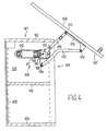
- FIGS. 1 and 2 show a cover plate according to the invention, in which a lid of a piece of furniture can be adjusted in parallel.
- a cabinet body 1 has a cabinet lid 2, a side wall 3, a cabinet bottom 4 and a rear wall 5. Within the cabinet body 1, an insert sheet 6 is provided.
- the cabinet body 1 forms an opening 7 which can be closed by a cover 8.
- the lid 8 is fixed by means of a cover plate 9 adjustable on the cabinet body 1.
- the cover plate 9 has an actuating arm 10 and a control arm 11.
- the actuator arm 10 is pivotally mounted to a housing 12 of the cover plate 9 about a first adjusting axis 13.
- the control arm 11 is pivotally mounted on the housing 12 about a first control axis 14.
- the first adjusting axis 13 and the first control axis 14 are parallel spaced from one another.
- the housing 12 is fixedly attached to the side wall 3.
- the adjusting arm 10 is pivotally connected to a fastening element 15 about a second adjusting axis 16.
- the fastening element 15 is attached to an inner surface 22 of the lid 8 with this.
- the second adjusting axis 16 is arranged at a distance parallel to the first adjusting axis 13.
- the control arm 11 is pivotally mounted about a second control axis 17 on the fastening element 15, wherein the second control axis 17 extends parallel to the first control axis 14 extends.
- the imaginary lines between the first adjusting axis 13 and the second adjusting axis 16 and the first control axis 14 and the second control axis 17 are the same length and parallel to each other, so that a parallelogram is clamped. This ensures that the lid 8 from the FIG. 2 shown closed position in the in FIG. 2 shown open position is adjustable in parallel.
- the control arm 10 has a setting contour 18. Against this, a lock slider 19 with a roller 20 is radially supported. The roller 20 is rotatably mounted on the lock slider 19. The lock slider 19 is acted upon by spring means 21 against the control contour 18.
- the radial distance of the setting contour 18 to the first adjusting axis 13 in the contact region between the adjusting slide 19 and the adjusting contour 18 increases at least over a first part of the pivoting path of the actuating arm 10, starting from an intermediate position of the actuating arm 10, which is arranged between the open position and the closed position Open position.
- the course of the control contour 18 is exactly matched to the weight of the lid 8, the actuator arm 10 and the control arm 11, that the lid 8 is held in any position.
- the torque that is generated by the adjusting slide 19, which is supported against the adjusting contour 18, thus changes over the pivoting path of the actuating arm 10, depending on how large the torque must be to hold the lid 8.
- FIGS. 3 and 4 show a lid plate, which allows a pivoting of a lid on a cabinet body. Corresponding components are provided with reference numerals which are increased by the value 100, and in the FIGS. 1 and 2 described.
- the distance between the first adjusting axis 113 and the second adjusting axis 116 is less than the distance between the first control axis 114 and the second control axis 117.
- an imaginary straight line intersect through the two Stellachsen 113, 116 and a straight line through the two control shafts 114 and 117 above the Deckelstellers 109, further wherein the first control axis 114 is disposed below the first adjusting axis 113, whereas in a Deckelsteller according to FIG. 1 is arranged above the first adjusting axis.
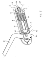
- the cover plate 9 is according to the FIGS. 1 and 2 in the following on the basis of Figures 5 and 6 described together.
- the actuator arm 10 is pivotally mounted in the housing 12 of the cover plate 9 about the first adjusting axis 13, wherein the housing 12 is fixedly connected to the side wall of the cabinet body.
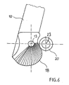
- the actuating arm 10 has a setting contour 18, which in Form of a curve about the first adjusting axis 13 is shown.
- the lock slider 19 is guided linearly displaceable.
- the steep slide 19 has a roller 20 which is rotatably mounted on the adjusting slide 19 about a rotation axis 23 which is arranged parallel to the first adjusting axis 13.
- Spring means 21 in the form of compression springs act on the locking slide 19 and thus the roller 20 against the setting contour 18.
- the spring means 21 are based on the one hand against the lock slider 19 and on the other hand against a support bearing 24 from , which is mounted linearly displaceable in the housing 12.
- the support bearing 24 is supported against a bearing surface 25 of an abutment 26, wherein the abutment 26 is rotatably mounted about an axis of rotation 27 in the housing 12 and wherein the bearing surface 25 has a variable distance from the axis of rotation 27 of the abutment 26, so that the support bearing 24 in a variable distance to the first adjusting axis 13 is held in the housing 12.
- the bearing surface 25 is helical and has radial locking recesses 28, in which a detent 29 of the support bearing 24 engages in order to prevent the abutment 26 is rotated unintentionally.
- the setting contour 18 of the actuating arm 10 is designed such that the radial distance of the adjusting contour 18 to the first adjusting axis 13 in the contact region between the adjusting slide 19, ie the roller 20, and the adjusting contour 18 via a pivoting path starting from the intermediate position of the actuating arm 10 to the open position on decreases an angular travel of the actuator arm 10.
- the actuating arm 10 is acted upon over the largest Winkelweg with a force that generates a moment to the upper position corresponding to the open position of the lid 8.
- the control contour 18 has a flattening over the course of the radial distance to the first control axis 13 decreases.
- the setting contour 18 is designed such that the generated torque in each pivot position of the actuating arm 10 corresponds to that counter-moment, which is generated by the weight of the cover 8 in total, so that the cover 8 is held in any position between the open position and the intermediate position.
Landscapes
- Engineering & Computer Science (AREA)
- Mechanical Engineering (AREA)
- Closing And Opening Devices For Wings, And Checks For Wings (AREA)
- Hinges (AREA)
- Cabinets, Racks, Or The Like Of Rigid Construction (AREA)
- Spinning Or Twisting Of Yarns (AREA)
- Closing Of Containers (AREA)
- Centrifugal Separators (AREA)
- Pivots And Pivotal Connections (AREA)
Description
- Die Erfindung betrifft einen Deckelsteller für einen Schrank umfassend
- einen Stellarm,
- der um eine erste Stellachse zwischen einer Offenstellung und einer Schließstellung schwenkbar an einer Seitenwand eines Schrankkorpus befestigbar ist,
- der um eine zweite Stellachse schwenkbar an einem Deckel befestigbar ist, und
- der eine Stellkontur aufweist, die um die erste Stellachse verläuft und die durch Stellmittel beaufschlagt ist,
- einen Steuerarm,
- der um eine erste Steuerachse zwischen einer Offenstellung und einer Schließstellung schwenkbar an der Seitenwand des Schrankkorpus befestigbar ist, wobei die erste Steuerachse parallel beabstandet zu der ersten Stellachse angeordnet ist, und
- der um eine zweite Steuerachse schwenkbar an dem Deckel befestigbar ist, wobei die zweite Steuerachse parallel beabstandet zu der zweiten Stellachse angeordnet ist.
- Ein solcher Deckelsteller ist in der
EP 0 044 081 A1 gezeigt. Die Stellkontur bildet hierbei einen Nocken mit zwei seitlichen Flanken, die als Rastanschläge für eine federbeaufschlagte Hülse dienen. Sowohl in der Offenstellung als auch in der Schließstellung hintergreift ein Rastvorsprung der Hülse einen der Rastanschläge, so dass der Deckel in der Offenstellung und in der Schließstellung gehalten ist. Zwischen der Offenstellung und der Schließstellung fällt die Klappe aufgrund der Schwerkraft in Richtung zur Schließstellung selbstständig zu. - Andere bekannte Deckelsteller weisen einen Stellarm und einen Steuerarm auf, die jeweils an einem Ende um parallel beabstandete Achsen zwischen einer Offenstellung und einer Schließstellung schwenkbar an einer Seitenwand eines Schrankkorpus befestigt sind. An ihren anderen Enden sind sie jeweils um parallel beabstandete Achsen schwenkbar an einem Deckel befestigt. Der Stellarm ist, z.B. durch einen Gasdruckspeicher oder eine Druckfeder, zur Offenstellung hin beaufschlagt. Über einen kleinen Schwenkweg zwischen einer Zwischenstellung und der Schließstellung ist der Stellarm zur Schließstellung hin beaufschlagt. Beim Öffnen des Deckels ist somit zunächst eine Anzugskraft zu überwinden, die dafür sorgt, dass der Deckel fest in der Schließstellung gehalten ist. Nach Überschreiten der Zwischenstellung fährt der Deckel dann von alleine in die Offenstellung. Beim Schließen ist dann die Kraft, die den Deckel in die Offenstellung überführt, zu überwinden. Einen Deckelsteller dieser Art zeigt
DE 94 00 568 U1 . - Nachteilig wirkt sich aus, dass der Deckel immer in die Offenstellung überführt wird und beim Schließen des Deckels eine relativ hohe Kraft aufgewendet werden muss, um den Deckel entgegen der ihn zu Offenstellung beaufschlagenden Kraft zu schließen.
- Die
DE 27 57 230 A1 zeigt einen Deckelsteller zum Anlenken eines Deckels einer Dunstabzugshaube mit einem Stellarm und einem Steuerarm, die beide jeweils an einem ihrer Enden um zueinander beabstandet angegeordnete Schwenkachsen an einem Scharnierteil befestigt sind. Das Scharnierteil ist an dem Korpus eines Möbels befestigt. Die anderen Enden der Arme sind um ebenfalls zueinander beabstandete Schwenkachsen mit dem Deckel der Dunstabzugshaube verbunden. Der Stellarm bildet eine Stellkontur mit Rastausnehmungen, in die ein Halteelement in Form eines Nockens eingreift. Der Nocken ist mittels einer Feder in Richtung zur Stellkontur und damit in die Rastausnehmungen beaufschlagt, wobei sich die Feder einerseits gegen den Nocken und andererseits gegen das Scharnierteil abstützt. Somit ist der Deckel der Dunstabzugshaube in beliebigen Schwenkpositionen gehalten, da der Nocken federbelastet in die Rastausnehmungen gedrückt wird, um ein Verschwenken des Steuerarms aufgrund der Schwerkraft, die auf den Deckel wirkt, zu vermeiden. In einer weiteren Ausführungsform ist anstelle der Rastausnehmungen ein Reibbelag vorgesehen, so dass die Reibkraft den Deckel in jeder beliebigen Position hält. Da der Deckel in der Schließposition senkrecht angeordnet ist und beim Öffnen des Deckels dieser hochgeklappt wird, vergrößert sich mit Annäherung an die Offenstellung das Drehmoment aufgrund der Gewichtskraft des Deckels. Somit ist mit Annäherung an die Offenposition des Deckels eine höhere Haltekraft durch den Nocken erforderlich, insbesondere wenn anstelle der Rastausnehmungen lediglich ein Reibbelag vorgesehen ist. Damit die Haltekraft des Nockens in der Rastausnehmung bzw. die Reibkraft des Nockens auf der Stellkontur groß genug ist bzw. an die Winkelposition des Deckels angepasst ist, nimmt der Radius der Stellkontur mit zunehmender Annäherung an die Offenposition zu. Somit wird die Feder bei der Bewegung in Richtung zur Offenposition zunehmend zusammengedrückt, so dass der Nocken mit stetig ansteigender Kraft gegen die Stellkontur gedrückt wird, so dass eine ausreichend große Kraft zum Halten des Nockens in der Ausnehmung oder zum Erzeugen einer ausreichend großen Reibungskraft erzeugt wird. - Die
EP 1 148 200 A2 betrifft einen Deckelsteller, der zwei Arme umfasst, welche über eine Gelenkachse gelenkig miteinander verbunden sind. Das freie Ende eines der Arme ist mit einem Deckel und das freie Ende des anderen Armes mit einem Korpus eines Möbels schwenkbar verbunden. Ferner ist der Deckel schwenkbar an dem Korpus befestigt. Dadurch, dass die beiden Arme des Deckelstellers jeweils schwenkbar mit dem Deckel bzw. dem Korpus verbunden sind und schwenkbar miteinander verbunden sind, eignet sich dieser Deckelsteller für Deckel, die an dem Korpus schwenkbar befestigt sind. Eine durch eine Druckrolle beaufschlagte Stellkontur um die Gelenkachse weist einen abnehmenden radialen Abstand zur Gelenkachse auf und trägt dazu bei, dass der Deckel über einen grossen Winkelbereich hinweg in Zwischenstellungen stehen bleibt. - Aufgabe der vorliegenden Erfindung ist es daher, einen Deckelsteller bereit zu stellen, bei dem ein Deckel parallel verstellt oder über den Korpus eines Schranks hinweggeschwenkt werden kann und bei dem der Deckel in jeder beliebigen Stellung gehalten ist.
- Die Aufgabe wird durch einen eingangs beschriebenen Deckelsteller gelöst, wobei die Stellkontur in Form einer Kurve ausgebildet ist, deren radialer Abstand zur ersten Stellachse zumindest über einen ersten Teil des Schwenkweges ausgehend von der Zwischenstellung, die sich zwischen der Offenstellung und der Schließstellung befindet, des Stellarms in Richtung zur Offenstellung abnimmt, so dass der Stellarm zumindest über den ersten Teil seines Schwenkweges zur Einnahme der Offenstellung mit Kraft beaufschlagt ist und ein Drehmoment erzeugt wird, das in jeder Schwenkstellung des ersten Teils des Schwenkweges demjenigen Gegenmoment entspricht, welches durch die Gewichtskraft des Deckels erzeugt wird, so dass der Deckel in jeder beliebigen Stellung zwischen der Offenstellung und der Zwischenstellung gehalten ist.
- Somit ist gewährleistet, dass der Deckel in jeder beliebigen Stellung gehalten ist. Da die Kraft zum Halten des Deckels so austariert ist, dass der Deckel nicht von selbst zur Offenstellung bewegt wird, ist auch eine geringere Kraft beim Schließen des Deckels zu überwinden.
- Die Stellkontur lässt sich jeder Anwendung, das heißt jedem Deckelgewicht und jeder Geometrie der Anlenkung des Stellarms und des Steuerarms, anpassen.
- Damit über einen kleinen Schwenkweg zwischen einer Zwischenstellung und der Schließstellung der Deckel nicht zur Offenstellung hin beaufschlagt ist, sondern eine Anzugskraft vorgesehen ist, die den Deckel in seine Schließstellung drückt, nimmt der radiale Abstand der Stellkontur zur ersten Stellachse über einen zweiten Teil des Schwenkweges ausgehend von der Schließstellung des Stellarms zur Zwischenstellung zu.
- Ein Gleitkontakt zwischen den Stellmitteln, die als Stellschieber ausgebildet sein können, und der Stellkontur würde zu einem hohen Verschleiß führen, so dass die Reibkräfte über die Lebensdauer stark variieren. Um dies zu vermeiden, kann der Stellschieber mit einer Rolle, die drehbar am Stellschieber gelagert ist, gegen die Stellkontur abgestützt sein.
- Hierbei kann der Stellschieber mittels Federmittel gegen die Stellkontur beaufschlagt sein. Eine gute Abstützung der Federmittel lässt sich dadurch erzielen, dass ein Stützlager vorgesehen ist, das in veränderbaren Abstand zur ersten Stellachse gehalten ist, und dass die Federmittel einerseits gegen den Stellschieber und andererseits gegen das Stützlager abgestützt sind.
- Um das Stützlager in veränderbaren Abstand zur ersten Stellachse zu halten, ist in einer bevorzugten Ausführungsform vorgesehen, dass das Stützlager gegen eine Lagerfläche eines Widerlagers abgestützt ist, welches um eine Drehachse drehbar gelagert ist, wobei die Lagerfläche in Umfangsrichtung einen veränderlichen Abstand zur Drehachse aufweist. Die Lagerfläche kann z.B. schneckenförmig gestaltet sein. In der Lagerfläche können zudem Rastvertiefungen vorgesehen sein, um definierte Drehstellungen des Widerlagers zu realisieren.
- Eine bevorzugte Ausführungsform des Deckelstellers weist ein Gehäuse auf, das an der Seitenwand des Schrankkorpus befestigbar ist und an dem der Stellarm um die erste Stellachse und der Steuerarm um die erste Steuerachse schwenkbar befestigt ist.
- Ferner kann ein Befestigungselement vorgesehen sein, an dem der Stellarm schwenkbar um die zweite Stellachse und der Steuerarm schwenkbar um die zweite Steuerachse befestigt ist und das an dem Deckel befestigbar ist.
- Um eine parallele Verstellung des Deckels zu erzielen, ist der Abstand zwischen der ersten Stellachse und der ersten Steuerachse und der Abstand zwischen der zweiten Stellachse und der zweiten Steuerachse gleich groß und der Abstand zwischen der ersten Stellachse und der zweiten Stellachse und der Abstand zwischen der ersten Steuerachse und der zweiten Steuerachse ebenfalls gleich groß.
- Bevorzugte Ausführungsbeispiele sind im folgenden anhand der Zeichnungen näher erläutert. Hierin zeigt
- Figur 1
- eine Schnittansicht eines Schrankkorpus mit einem erfindungsgemäßen Deckelsteller, wobei der Deckel in seiner Schließstellung dargestellt ist und sich parallel verstellen lässt;
- Figur 2
- eine Ansicht gemäß
Figur 1 , wobei der Deckel in seiner Offenstellung dargestellt ist; - Figur 3
- eine Schnittansicht eines Schrankkorpus mit einem erfindungsgemäßen Deckelsteller, wobei der Deckel in seiner Schließstellung dargestellt ist und sich über den Schrankkorpus verstellen lässt;
- Figur 4
- eine Ansicht gemäß
Figur 3 , wobei der Deckel in seiner Offenstellung dargestellt ist; - Figur 5
- eine perspektivische Darstellung eines Deckelstellers gemäß
Figur 1 und - Figur 6
- eine Ansicht der Stellkontur am Stellarm.
- Die
Figuren 1 und2 zeigen einen erfindungsgemäßen Deckelsteller, bei dem sich ein Deckel eines Möbels parallel verstellen lässt. Ein Schrankkorpus 1 weist einen Schrankdeckel 2, eine Seitenwand 3, einen Schrankboden 4 sowie eine Rückwand 5 auf. Innerhalb des Schrankkorpus 1 ist ein Einlegebogen 6 vorgesehen. Der Schrankkorpus 1 bildet eine Öffnung 7, die durch einen Deckel 8 verschließbar ist. Der Deckel 8 ist mittels eines Deckelstellers 9 verstellbar am Schrankkorpus 1 befestigt. Der Deckelsteller 9 weist einen Stellarm 10 sowie einen Steuerarm 11 auf. Der Stellarm 10 ist an einem Gehäuse 12 des Deckelstellers 9 schwenkbar um eine erste Stellachse 13 befestigt. Der Steuerarm 11 ist am Gehäuse 12 um eine erste Steuerachse 14 schwenkbar befestigt. Die erste Stellachse 13 und die erste Steuerachse 14 verlaufen parallel beabstandet zueinander. Das Gehäuse 12 ist fest an der Seitenwand 3 befestigt. - An einem der ersten Stellachse 13 entfernt angeordneten Ende ist der Stellarm 10 um eine zweite Stellachse 16 schwenkbar mit einem Befestigungselement 15 verbunden. Das Befestigungselement 15 ist an einer Innenfläche 22 des Deckels 8 mit diesem befestigt. Die zweite Stellachse 16 ist parallel beabstandet zur ersten Stellachse 13 angeordnet.
- Der Steuerarm 11 ist um eine zweite Steuerachse 17 schwenkbar am Befestigungselement 15 befestigt, wobei die zweite Steuerachse 17 parallel beabstandet zur ersten Steuerachse 14 verläuft.
- Die gedachten Linien zwischen der ersten Stellachse 13 und der zweiten Stellachse 16 sowie der ersten Steuerachse 14 und der zweiten Steuerachse 17 sind gleich lang und verlaufen parallel zueinander, so dass ein Parallelogramm aufgespannt ist. Somit ist gewährleistet, dass der Deckel 8 aus der
Figur 2 gezeigten Schließstellung in die inFigur 2 gezeigte Offenstellung parallel verstellbar ist. - Der Steuerarm 10 weist eine Stellkontur 18 auf. Gegen diese ist ein Stellschieber 19 mit einer Rolle 20 radial abgestützt. Die Rolle 20 ist drehbar am Stellschieber 19 befestigt. Der Stellschieber 19 ist mittels Federmittel 21 gegen die Stellkontur 18 beaufschlagt.
- Der radiale Abstand der Stellkontur 18 zur ersten Stellachse 13 im Kontaktbereich zwischen dem Stellschieber 19 und der Stellkontur 18 nimmt zumindest über einen ersten Teil des Schwenkweges des Stellarms 10 ausgehend von einer Zwischenstellung des Stellarms 10, die zwischen der Offenstellung und der Schließstellung angeordnet ist, zur Offenstellung ab. Hierbei ist der Verlauf der Stellkontur 18 genau so auf das Eigengewicht des Deckels 8, des Stellarms 10 und des Steuerarms 11 abgestimmt, dass der Deckel 8 in jeder beliebigen Position gehalten ist. Das Drehmoment, dass durch den Stellschieber 19, der gegen die Stellkontur 18 abgestützt ist, erzeugt wird, verändert sich somit über den Schwenkweg des Stellarms 10, je nach dem, wie groß das Drehmoment sein muss, um den Deckel 8 zu halten.
- Die
Figuren 3 und4 zeigen einen Deckelsteller, der ein Verschwenken eines Deckels über einen Schrankkorpus erlaubt. Übereinstimmende Bauteile sind mit Bezugszeichen versehen, die um den Wert 100 erhöht sind, und bei denFiguren 1 und2 beschrieben. - Um ein Abschwenken des Deckels 108 über den Schrankkorpus 101 zu gewährleisten, ist der Abstand zwischen der ersten Stellachse 113 und der zweiten Stellachse 116 geringer als der Abstand zwischen der ersten Steuerachse 114 und der zweiten Steuerachse 117. Zudem schneiden sich eine gedachte Gerade durch die beiden Stellachsen 113, 116 und eine Gerade durch die beiden Steuerachsen 114 und 117 oberhalb des Deckelstellers 109, wobei ferner die erste Steuerachse 114 unterhalb der ersten Stellachse 113 angeordnet ist, wohingegen diese bei einem Deckelsteller gemäß
Figur 1 oberhalb der ersten Stellachse angeordnet ist. Somit ist eine Offenposition wie inFigur 4 dargestellt möglich. - Der Deckelsteller 9 wird gemäß der
Figuren 1 und2 im folgenden anhand derFiguren 5 und6 zusammen beschrieben. - Der Stellarm 10 ist in dem Gehäuse 12 des Deckelstellers 9 um die erste Stellachse 13 schwenkbar gelagert, wobei das Gehäuse 12 fest mit der Seitenwand des Schrankkorpus verbunden ist. Der Stellarm 10 weist eine Stellkontur 18 auf, die in Form einer Kurve um die erste Stellachse 13 dargestellt ist.
- In dem Gehäuse 12 ist der Stellschieber 19 linear verschiebbar geführt. Der Steilschieber 19 weist eine Rolle 20 auf, die um eine Drehachse 23, welche parallel zur ersten Stellachse 13 angeordnet ist, drehbar am Stellschieber 19 gelagert. Mit einer Außenumfangsfläche ist die Rolle 20 in Anlage zur Stellkontur 18. Federmittel 21 in Form von Druckfedern beaufschlagen den Stellschieber 19 und damit die Rolle 20 gegen die Stellkontur 18. Die Federmittel 21 stützen sich einerseits gegen den Stellschieber 19 und andererseits gegen ein Stützlager 24 ab, welches linear verschiebbar im Gehäuse 12 gelagert ist. Das Stützlager 24 ist gegen eine Lagerfläche 25 eines Widerlagers 26 abgestützt, wobei das Widerlager 26 um eine Drehachse 27 drehbar im Gehäuse 12 gelagert ist und wobei die Lagerfläche 25 einen veränderlichen Abstand zur Drehachse 27 des Widerlagers 26 aufweist, so dass das Stützlager 24 in einem veränderbarem Abstand zur ersten Stellachse 13 im Gehäuse 12 gehalten ist. Die Lagerfläche 25 ist schneckenförmig ausgebildet und weist radiale Rastvertiefungen 28 auf, in die eine Rastnase 29 des Stützlagers 24 einrastet, um zu verhindern, dass das Widerlager 26 unbeabsichtigt gedreht wird.
- Die Stellkontur 18 des Stellarms 10 ist derart ausgebildet, dass der radiale Abstand der Stellkontur 18 zur ersten Stellachse 13 im Kontaktbereich zwischen dem Stellschieber 19, d. h. der Rolle 20, und der Stellkontur 18 über einen Schwenkweg ausgehend von der Zwischenposition des Stellarms 10 zur Offenstellung über einen Winkelweg des Stellarms 10 abnimmt. Somit ist gewährleistet, dass der Stellarm 10 über den größten Winkelweg mit einer Kraft beaufschlagt ist, die ein Moment zur oberen Position, die der Offenstellung des Deckels 8 entspricht, erzeugt. Über den Winkelweg ausgehend von der Zwischenstellung bis zur Schließstellung weist die Stellkontur 18 eine Abflachung auf, über deren Verlauf der radiale Abstand zur ersten Stellachse 13 abnimmt. Somit wird über diesen Schwenkweg ein Drehmoment erzeugt, welches den Stellarm 10 zur Schließstellung beaufschlagt. Die Stellkontur 18 ist derart ausgebildet, dass das erzeugte Drehmoment in jeder Schwenkstellung des Stellarms 10 demjenigen Gegenmoment entspricht, welches durch die Gewichtskraft des Deckels 8 insgesamt erzeugt wird, so dass der Deckel 8 in jeder Stellung zwischen der Offenstellung und der Zwischenstellung gehalten wird.
-
- 1, 101
- Schrankkorpus
- 2, 102
- Schraubdeckel
- 3, 103
- Seitenwand
- 4, 104
- Schrankboden
- 5, 105
- Rückwand
- 6, 106
- Einlegeboden
- 7, 107
- Öffnung
- 8, 108
- Deckel
- 9, 109
- Deckelsteller
- 10, 110
- Stellarm
- 11, 111
- Steuerarm
- 12,112
- Gehäuse
- 13, 113
- erste Stellachse
- 14, 114
- erste Steuerachse
- 15, 115
- Befestigungselement
- 16, 116
- Zweite Stellachse
- 17, 117
- Zweite Steuerachse
- 18, 118
- Stellkontur
- 19, 119
- Stellschieber
- 20, 120
- Rolle
- 21, 121
- Federmittel
- 22, 122
- Innenfläche
- 23
- Drehachse
- 24
- Stützlager
- 25
- Lagerfläche
- 26
- Widerlager
- 27
- Drehachse
- 28
- Rastvertiefung
- 29
- Rastnase
Claims (4)
- Deckelsteller für einen Schrank umfassend- einen Stellarm (10, 110),- der um eine erste Stellachse (13, 113) zwischen einer Offenstellung und einer Schließstellung schwenkbar an einer Seitenwand (3, 103) eines Schrankkorpus (1, 101) befestigbar ist,- der um eine zweite Stellachse (16, 116) schwenkbar an einem Deckel (8, 108) befestigbar ist, und- der eine Stellkontur (18, 118) aufweist, die um die erste Stellachse (13, 113) verläuft und die durch Stellmittel (19, 119) beaufschlagt ist,- einen Steuerarm (11, 111),dadurch gekennzeichnet,- der um eine erste Steuerachse (14, 114) zwischen einer Offenstellung und einer Schließstellung schwenkbar an der Seitenwand (3, 103) des Schrankkorpus (1, 101) befestigbar ist, wobei die erste Steuerachse (14, 114) parallel beabstandet zu der ersten Stellachse (13, 113) angeordnet ist, und- der um eine zweite Steuerachse (17, 117) schwenkbar an dem Deckel (8, 108) befestigbar ist, wobei die zweite Steuerachse (17, 117) parallel beabstandet zu der zweiten Stellachse (16, 116) angeordnet ist,
dass die Stellkontur (18, 118) in Form einer Kurve ausgebildet ist, deren radialer Abstand zur ersten Stellachse (13, 113) zumindest über einen ersten Teil des Schwenkweges ausgehend von der Zwischenstellung, die sich zwischen der Offenstellung und der Schließstellung befindet, des Stellarms (10, 110) in Richtung zur Offenstellung abnimmt, so dass der Stellarm (10, 110) zumindest über den ersten Teil seines Schwenkweges zur Einnahme der Offenstellung mit Kraft beaufschlagt ist und ein Drehmoment erzeugt wird, das in jeder Schwenkstellung des ersten Teils des Schwenkweges demjenigen Gegenmoment entspricht, welches durch die Gewichtskraft des Deckels erzeugt wird, so dass der Deckel (8, 118) in jeder beliebigen Stellung zwischen der Offenstellung und der Zwischenstellung gehalten ist. - Deckelsteller nach Anspruch 1,
dadurch gekennzeichnet,
dass der radiale Abstand der Stellkontur (18, 118) zur ersten Stellachse (13, 113) über einen zweiten Teil des Schwenkweges ausgehend von der Schließstellung des Stellarms (10, 110) zur Zwischenstellung zunimmt. - Deckelsteller nach einem der Ansprüche 1 oder 2,
dadurch gekennzeichnet,
dass die Stellmittel in Form eines Stellschiebers (19, 119) ausgebildet sind, der mit einer Rolle (20, 120), die drehbar am Stellschieber (19, 119) gelagert ist, gegen die Stellkontur (18, 118) abgestützt ist. - Deckelsteller nach einem der Ansprüche 1 bis 3,
dadurch gekennzeichnet,
dass die Stellmittel in Form eines Stellschiebers (19, 119) ausgebildet sind, der mittels Federmittel (21, 121) gegen die Stellkontur (18, 118) beaufschlagt ist.
Applications Claiming Priority (3)
| Application Number | Priority Date | Filing Date | Title |
|---|---|---|---|
| DE10223026A DE10223026C5 (de) | 2002-05-22 | 2002-05-22 | Deckelsteller |
| DE10223026 | 2002-05-22 | ||
| PCT/EP2003/005317 WO2003097973A1 (de) | 2002-05-22 | 2003-05-21 | Deckelsteller |
Publications (2)
| Publication Number | Publication Date |
|---|---|
| EP1507944A1 EP1507944A1 (de) | 2005-02-23 |
| EP1507944B1 true EP1507944B1 (de) | 2008-03-19 |
Family
ID=29432261
Family Applications (1)
| Application Number | Title | Priority Date | Filing Date |
|---|---|---|---|
| EP03735427A Expired - Lifetime EP1507944B1 (de) | 2002-05-22 | 2003-05-21 | Deckelsteller |
Country Status (7)
| Country | Link |
|---|---|
| US (1) | US7178202B2 (de) |
| EP (1) | EP1507944B1 (de) |
| AU (1) | AU2003237647A1 (de) |
| CA (1) | CA2490990C (de) |
| DE (2) | DE10223026C5 (de) |
| PL (1) | PL207363B1 (de) |
| WO (1) | WO2003097973A1 (de) |
Cited By (2)
| Publication number | Priority date | Publication date | Assignee | Title |
|---|---|---|---|---|
| DE202012102643U1 (de) | 2012-07-17 | 2013-07-18 | Kesseböhmer Beschlagsysteme GmbH & Co. KG | Deckelstelleranordnung für einen Eckschrank |
| IT202200011651A1 (it) * | 2022-06-01 | 2023-12-01 | Emuca S A | Dispositivo di movimentazione di ante a sollevamento |
Families Citing this family (77)
| Publication number | Priority date | Publication date | Assignee | Title |
|---|---|---|---|---|
| AT7499U1 (de) * | 2004-02-09 | 2005-04-25 | Blum Gmbh Julius | Stellarmantrieb für klappen von schränken |
| AT7500U1 (de) * | 2004-02-09 | 2005-04-25 | Blum Gmbh Julius | Stellarmantrieb für klappen von schränken |
| DE102004018273A1 (de) * | 2004-04-15 | 2005-11-10 | Bulthaup Gmbh & Co. Kg | Klappenmechanismus und Schrank mit einem Klappenmechanismus |
| DE102004019785B4 (de) * | 2004-04-23 | 2006-04-27 | Hetal-Werke Franz Hettich Gmbh & Co. Kg | Klappenbeschlag |
| BRPI0513268B1 (pt) * | 2004-07-14 | 2016-05-17 | Blum Gmbh Julius | mecanismo de atuação para um braço atuador apoiado podendo girar |
| AT502941B1 (de) | 2004-12-28 | 2011-05-15 | Blum Gmbh Julius | Stellantrieb zum antrieb einer klappe eines möbels |
| AT502944A1 (de) | 2005-03-21 | 2007-06-15 | Blum Gmbh Julius | Möbel mit einem möbelkorpus und wenigstens einer hochbewegbaren klappe |
| DE102005018552A1 (de) * | 2005-04-20 | 2006-11-02 | Huwil-Werke Gmbh Möbelschloss- Und Beschlagfabriken | Halteelement |
| AT502620B1 (de) * | 2005-10-12 | 2011-11-15 | Blum Gmbh Julius | Klappenbeschlag |
| DE102006013423A1 (de) * | 2006-03-23 | 2007-09-27 | Hetal-Werke Franz Hettich Gmbh & Co. Kg | Klappenhalter |
| ITMI20062235A1 (it) * | 2006-11-22 | 2008-05-23 | Agostino Ferrari Spa | Assieme di cerniera a quadrilatero articolato con barra stabilizzatrice adattabile per ante a movimento verticale |
| AT504671B1 (de) * | 2007-01-11 | 2012-07-15 | Blum Gmbh Julius | Dämpfer |
| DE202007005957U1 (de) * | 2007-02-19 | 2008-06-26 | Liebherr-Hausgeräte Ochsenhausen GmbH | Kühl- und/oder Gefriergerät |
| KR20080079113A (ko) * | 2007-02-26 | 2008-08-29 | 삼성전자주식회사 | 냉장고 |
| AT505126B1 (de) * | 2007-05-07 | 2009-05-15 | Blum Gmbh Julius | Klappenantriebssystem |
| DE202007006689U1 (de) * | 2007-05-07 | 2008-09-18 | Hetal-Werke Franz Hettich Gmbh & Co. Kg | Antriebseinrichtung für einen Beschlag |
| AT13257U1 (de) * | 2007-09-28 | 2013-09-15 | Blum Gmbh Julius | Stellmechanismus mit einem schwenkbar gelagerten Stellarm |
| JP4732417B2 (ja) * | 2007-10-03 | 2011-07-27 | スガツネ工業株式会社 | 可動保持具 |
| DE202007014560U1 (de) * | 2007-10-16 | 2009-03-12 | Hettich-Heinze Gmbh & Co. Kg | Angetriebener Beschlag |
| AT506196B1 (de) * | 2007-12-19 | 2010-10-15 | Blum Gmbh Julius | Stellmechanismus zum bewegen einer hochbewegbaren klappe eines möbels |
| DE102008005463A1 (de) * | 2008-01-21 | 2009-07-23 | Huwil-Werke Gmbh Möbelschloss- Und Beschlagfabriken | Halteelement zum Verstellen eines Deckels eines Möbels |
| AT506519B1 (de) * | 2008-03-06 | 2012-10-15 | Blum Gmbh Julius | Stellantrieb für eine möbelklappe mit einer montagesicherung für den leeren stellarm |
| DE102008025265B4 (de) * | 2008-05-27 | 2015-04-02 | HUWIL Bútoripari és Üzletberendezési Rendszerek kft | Faltdeckel |
| KR101527416B1 (ko) * | 2008-06-25 | 2015-06-10 | 삼성전자 주식회사 | 조리기기 |
| AT507279A1 (de) * | 2008-08-29 | 2010-03-15 | Blum Gmbh Julius | Antriebsvorrichtung für eine möbelklappe |
| KR100970472B1 (ko) * | 2008-12-12 | 2010-07-16 | 주식회사 다이아벨 | 스윙 힌지모듈 |
| US8201304B2 (en) * | 2009-02-25 | 2012-06-19 | General Electric Company | Compliant door hinge |
| DK2251517T3 (da) | 2009-05-11 | 2013-04-29 | Huwil Butoripari Es Uezletberendezesi | Holdeelement |
| AT508229B1 (de) * | 2009-05-13 | 2015-12-15 | Blum Gmbh Julius | Möbelklappenantrieb für verschiedene klappentypen |
| EP2430275B1 (de) * | 2009-05-13 | 2018-11-07 | Julius Blum GmbH | Klappenantriebssystem |
| AT508529A1 (de) * | 2009-07-28 | 2011-02-15 | Blum Gmbh Julius | Stellantrieb für ein bewegbares möbelteil |
| AT508698B1 (de) | 2009-08-20 | 2017-07-15 | Blum Gmbh Julius | Möbel mit stellarmanordnung |
| EP2559835A4 (de) * | 2010-04-16 | 2017-12-20 | Sugatsune Kogyo CO., LTD. | Türöffnungs-/-schliessvorrichtung |
| JP5161336B2 (ja) * | 2010-09-10 | 2013-03-13 | 三菱製鋼株式会社 | 開閉装置 |
| DE202010015092U1 (de) * | 2010-11-04 | 2012-02-06 | Grass Gmbh | Möbelbeschlag und Möbel |
| DE202010014948U1 (de) * | 2010-11-04 | 2012-02-06 | Grass Gmbh | Vorrichtung zum Antrieb eines beweglichen Möbelteils |
| DE202011004678U1 (de) | 2011-03-31 | 2011-07-08 | Thomas Kraft | Schrank mit einem Scharnier |
| DE102011015719B3 (de) * | 2011-03-31 | 2011-11-03 | Thomas Kraft | Schrank mit einem Scharnier |
| US20120266857A1 (en) * | 2011-04-20 | 2012-10-25 | Chuan-Yi Lin | Barbeque grill lift cover structure |
| ES2724779T3 (es) * | 2012-01-30 | 2019-09-16 | Blum Gmbh Julius | Servoaccionamiento para una tapa abatible de un mueble |
| US8925346B2 (en) * | 2012-02-07 | 2015-01-06 | Thermo Fisher Scientific (Asheville) Llc | High performance freezer having cylindrical cabinet |
| CN104583518B (zh) * | 2012-09-25 | 2016-10-26 | 世嘉智尼工业株式会社 | 门扇开闭装置 |
| US10012225B2 (en) * | 2012-11-14 | 2018-07-03 | Adamant Namiki Preccision Jewel Co., Ltd. | Tubing pump |
| US9515460B1 (en) * | 2013-05-30 | 2016-12-06 | Cooper Technologies Company | Streetlight base |
| AT515492B1 (de) | 2014-03-14 | 2020-01-15 | Blum Gmbh Julius | Stellantrieb für Möbelklappen |
| AT515661B1 (de) | 2014-11-21 | 2015-11-15 | Blum Gmbh Julius | Stellantrieb für bewegbare Möbelteile |
| ES2829402T3 (es) * | 2015-02-17 | 2021-05-31 | Salice Arturo Spa | Sistema de elevación para hojas de mobiliario |
| DE102015102393A1 (de) * | 2015-02-19 | 2016-08-25 | Hettich Holding Gmbh & Co. Ohg | Schwenkbeschlag |
| BR112017021309A2 (pt) * | 2015-04-30 | 2018-06-26 | Salice Arturo Spa | dobradiça para folhas de mobiliário que oscilam em torno de pelo menos um eixo horizontal |
| US10221058B2 (en) * | 2015-10-09 | 2019-03-05 | Cornelius, Inc. | Maneuverable service door for beverage dispensing machines |
| ITUB20156022A1 (it) * | 2015-11-30 | 2017-05-30 | Leandro Cappellotto | Meccanismo di movimentazione di ante di mobili |
| AT16381U1 (de) * | 2016-02-26 | 2019-08-15 | Blum Gmbh Julius | Stellarmantrieb |
| IT201600098088A1 (it) * | 2016-09-30 | 2018-03-30 | Salice Arturo Spa | Dispositivo di comando per un sistema di sollevamento e sistema di sollevamento per ante di mobili. |
| DE102016123806A1 (de) * | 2016-12-08 | 2018-06-14 | Still Gmbh | Flurförderzeug, insbesondere elektrisch betriebenes Flurförderzeug |
| IT201700044196A1 (it) * | 2017-04-21 | 2018-10-21 | Effegi Brevetti Srl | Meccanismo di movimentazione di un’anta di mobile |
| DE102017114776A1 (de) * | 2017-07-03 | 2019-01-03 | Hettich-Oni Gmbh & Co. Kg | Dämpferanordnung und Klappenbeschlag |
| DE102017114772A1 (de) * | 2017-07-03 | 2019-01-03 | Hettich-Oni Gmbh & Co. Kg | Klappenbeschlag und Möbel |
| EP3460154A1 (de) * | 2017-09-26 | 2019-03-27 | FLAP Competence Center kft | Halteelement für einen deckel oder eine klappe eines möbels |
| US10521998B2 (en) | 2017-09-29 | 2019-12-31 | Aristocrat Technologies Australia Pty Limited | Zero weight articulating access door |
| KR20190089156A (ko) * | 2018-01-16 | 2019-07-30 | 동관 쿠모 퍼니쳐 컴퍼니 리미티드 | 지지장치 및 지지장치가 달린 접이식 가구 |
| PL3521542T3 (pl) | 2018-01-31 | 2020-06-29 | Flap Competence Center Kft | Nastawnik pokrywy mebla |
| PL3623559T3 (pl) * | 2018-09-14 | 2021-12-13 | Flap Competence Center Kft | Okucie pokrywowe do przechylnego mocowania pokrywy na korpusie meblowym |
| DE102019100188A1 (de) * | 2019-01-07 | 2020-07-09 | Grass Gmbh | Vorrichtung zum Bewegen einer Möbelklappe und Möbel |
| AT522287A1 (de) * | 2019-03-20 | 2020-10-15 | Blum Gmbh Julius | Federführung |
| PL3719242T3 (pl) | 2019-04-02 | 2021-12-13 | Flap Competence Center Kft | Okucie klapowe |
| DE102019113337B4 (de) * | 2019-05-20 | 2022-07-14 | Samet Kalip Ve Maden Esya San. Ve Tic. A.S. | Möbelbeschlag |
| CN110284790B (zh) * | 2019-07-23 | 2024-05-10 | 广东星徽精密制造股份有限公司 | 一种翻门铰链机构 |
| USD913198S1 (en) | 2019-07-31 | 2021-03-16 | Gulfstream Aerospace Corporation | Galley upper for an aircraft |
| US11549295B2 (en) | 2019-08-28 | 2023-01-10 | Gulfstream Aerospace Corporation | Cabinet and method for making the same, and aircraft including a cabinet |
| AT524337B1 (de) * | 2020-10-22 | 2023-07-15 | Blum Gmbh Julius | Möbelantrieb |
| AT524339B1 (de) * | 2020-10-22 | 2023-10-15 | Blum Gmbh Julius | Möbelantrieb zum Bewegen einer Möbelfront |
| EP4103023B1 (de) * | 2020-12-18 | 2024-05-15 | Versuni Holding B.V. | Küchengerät mit deckel |
| IT202100025982A1 (it) * | 2021-10-11 | 2023-04-11 | Effegi Brevetti Srl | Dispositivo di apertura di ante a sollevamento |
| IT202200000716A1 (it) * | 2022-01-18 | 2023-07-18 | Nuova Star Spa | Cerniera per sportelli di elettrodomestici |
| WO2024165897A1 (ru) * | 2023-02-12 | 2024-08-15 | Роман БОЛЬШИЯНОВ | Устройство поворотно-выдвижного открытия и закрытия дверей |
| DE102024115834A1 (de) * | 2024-06-06 | 2025-12-11 | Flap Competence Center Kft | Hebelarm für einen möbelbeschlag zum gelenkigen verbinden eines bewegbaren möbelteils mit einem möbelkorpus |
| DE102024119092A1 (de) * | 2024-07-04 | 2026-01-08 | Flap Competence Center Kft | Möbelbeschlag zum bewegen eines an einem möbelkorpus bewegbar angeordneten möbelelements |
Citations (5)
| Publication number | Priority date | Publication date | Assignee | Title |
|---|---|---|---|---|
| DE2757230A1 (de) * | 1977-12-22 | 1979-07-05 | Hettich Hetal Werke | Scharnier |
| DE2829727A1 (de) * | 1978-07-06 | 1980-01-24 | Hettich Hetal Werke | Moebelbeschlag |
| DE2653106C2 (de) * | 1976-11-23 | 1984-04-26 | Richard Heinze Gmbh & Co Kg, 4900 Herford | Klappenhalter |
| DE29903503U1 (de) * | 1999-02-26 | 1999-05-20 | Huwil-Werke GmbH Möbelschloß- und Beschlagfabriken, 53809 Ruppichteroth | Steller für Deckel |
| EP1148200A2 (de) * | 2000-04-19 | 2001-10-24 | Hetal-Werke Franz Hettich GmbH & Co. | Klappenhalter |
Family Cites Families (7)
| Publication number | Priority date | Publication date | Assignee | Title |
|---|---|---|---|---|
| US2161323A (en) * | 1938-08-15 | 1939-06-06 | Om Edwards Co Inc | Latch mechanism for desk tops |
| US3088727A (en) * | 1958-06-19 | 1963-05-07 | Magneti Marelli Spa | Control device of a window regulator in motor car doors |
| DE2518942A1 (de) * | 1975-04-29 | 1976-11-18 | Lippische Felgen U Schutzblech | Schwenkbeschlag fuer vor ein moebel ausschwenkbare arbeitsplatten |
| DE3026630C2 (de) * | 1980-07-14 | 1983-05-11 | Arturo Salice S.p.A., 22060 Novedrate, Como | Scharnier mit Bremsvorrichtung für um horizontale Achsen schwenkbare Klappen o.dgl. |
| DE9400568U1 (de) * | 1994-01-14 | 1994-03-03 | Steltemeier GmbH, 59557 Lippstadt | Beschlag zum Öffnen einer Schrank- oder Vitrinentür in vertikaler Richtung |
| TW334493B (en) * | 1996-05-14 | 1998-06-21 | Sugatsune Kogyo | Damper for opening or closing a door |
| ES2320086T3 (es) * | 2000-05-12 | 2009-05-19 | Antonio Giovannetti | Dispositivo accionado por resorte para el movimiento de una puerta, con un brazo de palanca ajustable del resorte. |
-
2002
- 2002-05-22 DE DE10223026A patent/DE10223026C5/de not_active Expired - Fee Related
-
2003
- 2003-05-21 CA CA 2490990 patent/CA2490990C/en not_active Expired - Fee Related
- 2003-05-21 WO PCT/EP2003/005317 patent/WO2003097973A1/de not_active Ceased
- 2003-05-21 PL PL374114A patent/PL207363B1/pl unknown
- 2003-05-21 US US10/515,835 patent/US7178202B2/en not_active Expired - Lifetime
- 2003-05-21 EP EP03735427A patent/EP1507944B1/de not_active Expired - Lifetime
- 2003-05-21 DE DE50309416T patent/DE50309416D1/de not_active Expired - Lifetime
- 2003-05-21 AU AU2003237647A patent/AU2003237647A1/en not_active Abandoned
Patent Citations (5)
| Publication number | Priority date | Publication date | Assignee | Title |
|---|---|---|---|---|
| DE2653106C2 (de) * | 1976-11-23 | 1984-04-26 | Richard Heinze Gmbh & Co Kg, 4900 Herford | Klappenhalter |
| DE2757230A1 (de) * | 1977-12-22 | 1979-07-05 | Hettich Hetal Werke | Scharnier |
| DE2829727A1 (de) * | 1978-07-06 | 1980-01-24 | Hettich Hetal Werke | Moebelbeschlag |
| DE29903503U1 (de) * | 1999-02-26 | 1999-05-20 | Huwil-Werke GmbH Möbelschloß- und Beschlagfabriken, 53809 Ruppichteroth | Steller für Deckel |
| EP1148200A2 (de) * | 2000-04-19 | 2001-10-24 | Hetal-Werke Franz Hettich GmbH & Co. | Klappenhalter |
Cited By (3)
| Publication number | Priority date | Publication date | Assignee | Title |
|---|---|---|---|---|
| DE202012102643U1 (de) | 2012-07-17 | 2013-07-18 | Kesseböhmer Beschlagsysteme GmbH & Co. KG | Deckelstelleranordnung für einen Eckschrank |
| IT202200011651A1 (it) * | 2022-06-01 | 2023-12-01 | Emuca S A | Dispositivo di movimentazione di ante a sollevamento |
| WO2023232308A1 (en) | 2022-06-01 | 2023-12-07 | Emuca S.A | Lift-up door movement device |
Also Published As
| Publication number | Publication date |
|---|---|
| CA2490990C (en) | 2008-08-05 |
| WO2003097973A1 (de) | 2003-11-27 |
| PL374114A1 (en) | 2005-10-03 |
| DE10223026B3 (de) | 2004-02-12 |
| DE10223026C5 (de) | 2007-11-08 |
| US20050218383A1 (en) | 2005-10-06 |
| AU2003237647A1 (en) | 2003-12-02 |
| PL207363B1 (pl) | 2010-12-31 |
| DE50309416D1 (de) | 2008-04-30 |
| EP1507944A1 (de) | 2005-02-23 |
| US7178202B2 (en) | 2007-02-20 |
| WO2003097973A8 (de) | 2005-02-17 |
| CA2490990A1 (en) | 2003-11-27 |
Similar Documents
| Publication | Publication Date | Title |
|---|---|---|
| DE10223026C5 (de) | Deckelsteller | |
| EP1296011B1 (de) | Faltdeckel | |
| EP2238306B1 (de) | Halteelement zum verstellen eines deckels eines möbels | |
| EP1287222B1 (de) | Scharnier für eine herdklappe | |
| EP2003276B1 (de) | Stellmechanismus für einen schwenkbar gelagerten Stellarm | |
| DE19918823C1 (de) | Deckelsteller | |
| EP3527762B1 (de) | Mehrgelenkscharnier | |
| EP2140091B1 (de) | Doppellenkerscharnier | |
| DE10019337A1 (de) | Klappenhalter | |
| EP2307644A1 (de) | Faltdeckel | |
| WO2013149632A1 (de) | Vorrichtung für ein bewegbares möbelteil und möbel | |
| EP1999328B1 (de) | Klappenhalter für eine möbelklappe | |
| EP1840309B1 (de) | Klappenhalter für eine Möbelklappe | |
| EP2309086B1 (de) | Halteelement zum Verstellen eines Deckels eines Möbels | |
| EP3621483A1 (de) | Haltevorrichtung für eine frontblende einer schublade | |
| DE102007037480A1 (de) | Möbelscharnier | |
| EP2251514A1 (de) | Deckelsteller | |
| EP3623559B1 (de) | Deckelbeschlag zum schwenkbaren befestigen eines deckels an einen möbelkorpus | |
| EP1988242A2 (de) | Klappenhalter für eine Möbelklappe | |
| DE3026630C2 (de) | Scharnier mit Bremsvorrichtung für um horizontale Achsen schwenkbare Klappen o.dgl. | |
| DE202008011372U1 (de) | Dämpfungsvorrichtung | |
| EP1625270B1 (de) | Deckelsteller | |
| DE19642637C2 (de) | Türscharnier zur schwenkbaren Lagerung eines Türflügels an einem Türrahmen | |
| DE102016100606B3 (de) | Deckelsteller | |
| AT413728B (de) | Scharnier |
Legal Events
| Date | Code | Title | Description |
|---|---|---|---|
| PUAI | Public reference made under article 153(3) epc to a published international application that has entered the european phase |
Free format text: ORIGINAL CODE: 0009012 |
|
| 17P | Request for examination filed |
Effective date: 20041214 |
|
| AK | Designated contracting states |
Kind code of ref document: A1 Designated state(s): AT BE BG CH CY CZ DE DK EE ES FI FR GB GR HU IE IT LI LU MC NL PT RO SE SI SK TR |
|
| AX | Request for extension of the european patent |
Extension state: AL LT LV MK |
|
| DAX | Request for extension of the european patent (deleted) | ||
| RIN1 | Information on inventor provided before grant (corrected) |
Inventor name: REINEKING, CHRISTIAN Inventor name: HIRTSIEFER, ARTUR Inventor name: SCHNELL, JUERGEN |
|
| GRAP | Despatch of communication of intention to grant a patent |
Free format text: ORIGINAL CODE: EPIDOSNIGR1 |
|
| GRAS | Grant fee paid |
Free format text: ORIGINAL CODE: EPIDOSNIGR3 |
|
| GRAA | (expected) grant |
Free format text: ORIGINAL CODE: 0009210 |
|
| RBV | Designated contracting states (corrected) |
Designated state(s): DE IT |
|
| AK | Designated contracting states |
Kind code of ref document: B1 Designated state(s): DE IT |
|
| REF | Corresponds to: |
Ref document number: 50309416 Country of ref document: DE Date of ref document: 20080430 Kind code of ref document: P |
|
| RAP2 | Party data changed (patent owner data changed or rights of a patent transferred) |
Owner name: HUWIL-WERKE GMBH MOEBELSCHLOSS- UND BESCHLAGFABRIK |
|
| PLBE | No opposition filed within time limit |
Free format text: ORIGINAL CODE: 0009261 |
|
| STAA | Information on the status of an ep patent application or granted ep patent |
Free format text: STATUS: NO OPPOSITION FILED WITHIN TIME LIMIT |
|
| 26N | No opposition filed |
Effective date: 20081222 |
|
| REG | Reference to a national code |
Ref country code: DE Ref legal event code: R082 Ref document number: 50309416 Country of ref document: DE Representative=s name: NEUMANN MUELLER OBERWALLENEY & PARTNER PATENTA, DE Effective date: 20110916 Ref country code: DE Ref legal event code: R081 Ref document number: 50309416 Country of ref document: DE Owner name: HUWIL BUTORIPARI ES UEZIETBERENDEZESI RENDSZER, HU Free format text: FORMER OWNER: HUWIL-WERKE GMBH MOEBELSCHLOSS- UND BESCHLAGFABRIKEN, 53809 RUPPICHTEROTH, DE Effective date: 20110916 Ref country code: DE Ref legal event code: R081 Ref document number: 50309416 Country of ref document: DE Owner name: HUWIL BUTORIPARI ES UEZLETBERENDEZESI RENDSZER, HU Free format text: FORMER OWNER: HUWIL-WERKE GMBH MOEBELSCHLOSS- UND BESCHLAGFABRIKEN, 53809 RUPPICHTEROTH, DE Effective date: 20110916 Ref country code: DE Ref legal event code: R081 Ref document number: 50309416 Country of ref document: DE Owner name: FLAP COMPETENCE CENTER KFT, HU Free format text: FORMER OWNER: HUWIL-WERKE GMBH MOEBELSCHLOSS- UND BESCHLAGFABRIKEN, 53809 RUPPICHTEROTH, DE Effective date: 20110916 |
|
| REG | Reference to a national code |
Ref country code: DE Ref legal event code: R082 Ref document number: 50309416 Country of ref document: DE Representative=s name: NEUMANN MUELLER OBERWALLENEY & PARTNER PATENTA, DE |
|
| REG | Reference to a national code |
Ref country code: DE Ref legal event code: R082 Ref document number: 50309416 Country of ref document: DE Representative=s name: NEUMANN MUELLER OBERWALLENEY & PARTNER PATENTA, DE Effective date: 20120702 Ref country code: DE Ref legal event code: R081 Ref document number: 50309416 Country of ref document: DE Owner name: HUWIL BUTORIPARI ES UEZLETBERENDEZESI RENDSZER, HU Free format text: FORMER OWNER: TOPLIFTER BETEILIGUNGS- UND VERTRIEBS-GMBH & CO. KG, 49152 BAD ESSEN, DE Effective date: 20120702 Ref country code: DE Ref legal event code: R081 Ref document number: 50309416 Country of ref document: DE Owner name: FLAP COMPETENCE CENTER KFT, HU Free format text: FORMER OWNER: TOPLIFTER BETEILIGUNGS- UND VERTRIEBS-GMBH & CO. KG, 49152 BAD ESSEN, DE Effective date: 20120702 |
|
| REG | Reference to a national code |
Ref country code: DE Ref legal event code: R082 Ref document number: 50309416 Country of ref document: DE Representative=s name: NEUMANN MUELLER OBERWALLENEY & PARTNER PATENTA, DE |
|
| REG | Reference to a national code |
Ref country code: DE Ref legal event code: R081 Ref document number: 50309416 Country of ref document: DE Owner name: HUWIL BUTORIPARI ES UEZLETBERENDEZESI RENDSZER, HU Free format text: FORMER OWNER: HUWIL BUTORIPARI ES UEZIETBERENDEZESI RENDSZEREK KFT, BUDAPEST, HU Effective date: 20140416 Ref country code: DE Ref legal event code: R082 Ref document number: 50309416 Country of ref document: DE Representative=s name: NEUMANN MUELLER OBERWALLENEY & PARTNER PATENTA, DE Effective date: 20140416 Ref country code: DE Ref legal event code: R081 Ref document number: 50309416 Country of ref document: DE Owner name: FLAP COMPETENCE CENTER KFT, HU Free format text: FORMER OWNER: HUWIL BUTORIPARI ES UEZIETBERENDEZESI RENDSZEREK KFT, BUDAPEST, HU Effective date: 20140416 |
|
| REG | Reference to a national code |
Ref country code: DE Ref legal event code: R082 Ref document number: 50309416 Country of ref document: DE Representative=s name: NEUMANN MUELLER OBERWALLENEY & PARTNER PATENTA, DE |
|
| REG | Reference to a national code |
Ref country code: DE Ref legal event code: R082 Ref document number: 50309416 Country of ref document: DE Representative=s name: NEUMANN MUELLER OBERWALLENEY & PARTNER PATENTA, DE Effective date: 20150511 Ref country code: DE Ref legal event code: R081 Ref document number: 50309416 Country of ref document: DE Owner name: FLAP COMPETENCE CENTER KFT, HU Free format text: FORMER OWNER: HUWIL BUTORIPARI ES UEZLETBERENDEZESI RENDSZEREK KFT, BUDAPEST, HU Effective date: 20150511 |
|
| PGFP | Annual fee paid to national office [announced via postgrant information from national office to epo] |
Ref country code: IT Payment date: 20210531 Year of fee payment: 19 |
|
| PGFP | Annual fee paid to national office [announced via postgrant information from national office to epo] |
Ref country code: DE Payment date: 20220519 Year of fee payment: 20 |
|
| REG | Reference to a national code |
Ref country code: DE Ref legal event code: R071 Ref document number: 50309416 Country of ref document: DE |
|
| P01 | Opt-out of the competence of the unified patent court (upc) registered |
Effective date: 20230329 |
|
| PG25 | Lapsed in a contracting state [announced via postgrant information from national office to epo] |
Ref country code: IT Free format text: LAPSE BECAUSE OF NON-PAYMENT OF DUE FEES Effective date: 20220521 |