EP1501690B1 - Verfahren zum dekorieren eines grossen, dreidimensionalen plastikgegenstandes - Google Patents
Verfahren zum dekorieren eines grossen, dreidimensionalen plastikgegenstandes Download PDFInfo
- Publication number
- EP1501690B1 EP1501690B1 EP02758198A EP02758198A EP1501690B1 EP 1501690 B1 EP1501690 B1 EP 1501690B1 EP 02758198 A EP02758198 A EP 02758198A EP 02758198 A EP02758198 A EP 02758198A EP 1501690 B1 EP1501690 B1 EP 1501690B1
- Authority
- EP
- European Patent Office
- Prior art keywords
- thermal transfer
- molded article
- transfer foil
- foil
- molded
- Prior art date
- Legal status (The legal status is an assumption and is not a legal conclusion. Google has not performed a legal analysis and makes no representation as to the accuracy of the status listed.)
- Expired - Lifetime
Links
Images


Classifications
-
- B—PERFORMING OPERATIONS; TRANSPORTING
- B44—DECORATIVE ARTS
- B44C—PRODUCING DECORATIVE EFFECTS; MOSAICS; TARSIA WORK; PAPERHANGING
- B44C1/00—Processes, not specifically provided for elsewhere, for producing decorative surface effects
- B44C1/10—Applying flat materials, e.g. leaflets, pieces of fabrics
-
- B—PERFORMING OPERATIONS; TRANSPORTING
- B29—WORKING OF PLASTICS; WORKING OF SUBSTANCES IN A PLASTIC STATE IN GENERAL
- B29C—SHAPING OR JOINING OF PLASTICS; SHAPING OF MATERIAL IN A PLASTIC STATE, NOT OTHERWISE PROVIDED FOR; AFTER-TREATMENT OF THE SHAPED PRODUCTS, e.g. REPAIRING
- B29C37/00—Component parts, details, accessories or auxiliary operations, not covered by group B29C33/00 or B29C35/00
- B29C37/0025—Applying surface layers, e.g. coatings, decorative layers, printed layers, to articles during shaping, e.g. in-mould printing
-
- B—PERFORMING OPERATIONS; TRANSPORTING
- B29—WORKING OF PLASTICS; WORKING OF SUBSTANCES IN A PLASTIC STATE IN GENERAL
- B29C—SHAPING OR JOINING OF PLASTICS; SHAPING OF MATERIAL IN A PLASTIC STATE, NOT OTHERWISE PROVIDED FOR; AFTER-TREATMENT OF THE SHAPED PRODUCTS, e.g. REPAIRING
- B29C63/00—Lining or sheathing, i.e. applying preformed layers or sheathings of plastics; Apparatus therefor
- B29C63/0073—Lining or sheathing, i.e. applying preformed layers or sheathings of plastics; Apparatus therefor of non-flat surfaces, e.g. curved, profiled
-
- B—PERFORMING OPERATIONS; TRANSPORTING
- B44—DECORATIVE ARTS
- B44C—PRODUCING DECORATIVE EFFECTS; MOSAICS; TARSIA WORK; PAPERHANGING
- B44C1/00—Processes, not specifically provided for elsewhere, for producing decorative surface effects
- B44C1/16—Processes, not specifically provided for elsewhere, for producing decorative surface effects for applying transfer pictures or the like
- B44C1/165—Processes, not specifically provided for elsewhere, for producing decorative surface effects for applying transfer pictures or the like for decalcomanias; sheet material therefor
- B44C1/17—Dry transfer
- B44C1/1712—Decalcomanias applied under heat and pressure, e.g. provided with a heat activable adhesive
- B44C1/1729—Hot stamping techniques
-
- B—PERFORMING OPERATIONS; TRANSPORTING
- B29—WORKING OF PLASTICS; WORKING OF SUBSTANCES IN A PLASTIC STATE IN GENERAL
- B29C—SHAPING OR JOINING OF PLASTICS; SHAPING OF MATERIAL IN A PLASTIC STATE, NOT OTHERWISE PROVIDED FOR; AFTER-TREATMENT OF THE SHAPED PRODUCTS, e.g. REPAIRING
- B29C2793/00—Shaping techniques involving a cutting or machining operation
-
- B—PERFORMING OPERATIONS; TRANSPORTING
- B29—WORKING OF PLASTICS; WORKING OF SUBSTANCES IN A PLASTIC STATE IN GENERAL
- B29L—INDEXING SCHEME ASSOCIATED WITH SUBCLASS B29C, RELATING TO PARTICULAR ARTICLES
- B29L2031/00—Other particular articles
- B29L2031/722—Decorative or ornamental articles
Definitions
- the present invention relates to a method used for the decoration of plastic molded articles, and relates to a thermal transfer technique and the so-called three-dimensional hot stamp decoration technique, which performs decoration by causing a thermal transfer foil to cover a surface of a large plastic molded article having a three-dimensional shape; clamping the perimeter of the thermal transfer foil; attaching the foil to the molded article shape by means of vacuum degassing; and thereafter lowering and raising a molded rubber mold.
- molded article As methods for decorating a surface of a large plastic molded article (referred to as "molded article” hereinafter), methods exist which perform decoration by transferring a thermal transfer foil design to a surface of a molded article by causing a thermal transfer foil to cover a molded article; pressing the perimeter of the thermal transfer foil; attaching the thermal transfer foil to the molded article by means of vacuum extraction, whereupon the foil adopts a shape like that of the molded article; and lowering and raising a heated "molded rubber mold”.
- This method is known as three-dimensional hot stamping. This technique will be described in detail hereinbelow using specific examples.
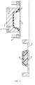
- a molded article such as that illustrated in Fig. 1 is presented as an article for decoration.
- the dimensions of this molded article are: length 900 mm, width 300 mm, height 50 mm, and wall face height 25 mm.
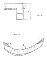
- an outside view and a cross-sectional view of the molded rubber mold for hot stamping are shown in Figs. 2, 3.
- a bar-shaped heater 9 is fitted thereon, and [the molded rubber mold with heater] is mounted on a stamp device which has a lowering and raising mechanism as shown in Fig. 4.
- This stamp device has a slide table 4 on whose inner face a support jig 5, which is for securing a product made of aluminum manufactured so as to match the shape of the molded article (referred to as "support jig" hereinafter), is arranged.
- the mold support jig and device as described above, first the molded article 6 is fixed to the top of the support jig 5 as shown in Fig. 4. Thereupon, a thermal transfer foil 7 is set using a foil chuck over a space into which the slide table is to be introduced once. Next, the slide table is moved to below the molded rubber mold as far as the state in Fig. 5, and the thermal transfer foil 7 is secured by lowering the foil clamp 8. Then, cutting of the thermal transfer foil 7 on the roll side is performed using a foil cutter. Next, by removing the air in an enclosure 10 contained by the support jig 5 and the molded article 6, using a vacuum pump, the thermal transfer foil 7 is caused to adhere to the molded article 6.
- the thermal transfer foil 7 Following adequate adhesion of the thermal transfer foil 7, heat and pressure are applied by lowering the molded rubber mold 3 as shown in Fig. 6, such that the design is transferred to the molded article 6. Thereafter, after raising the molded rubber mold 3 as shown in Fig. 7, the position of the slide table 4 is moved as shown in Fig. 8, and after peeling the thermal transfer foil 7 from the surface of the molded article 6, the molded article 6 thus decorated is removed.
- the peeling of the thermal transfer foil 7 may also be performed following removal of the molded article 6 from the support jig 5. Following peeling of the thermal transfer foil 7, in cases where foil burrs remain on the grating portions, the grating portions are rubbed using a sponge, and then, by running a cleaner, finishing of the decorated article is performed.
- thermal transfer foil 7 is supplied continuously using a foil roll, and the thermal transfer foil 7 is peeled in foil peeling bars after transfer have also already been implemented as mass production methods.
- the molded rubber mold makes contact with the thermal transfer foil at the perimeter of the molded article before reaching the drop point, that is, the molded article surface, and the thermal transfer foil is tom (referred to as foil splitting hereinafter).
- foil splitting the thermal transfer foil is tom
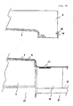
- a side upright portion is of a comparatively undulating shape, where the angle ⁇ is an obtuse angle, as shown in Figs. 9 to 12.
- thermal transfer foil For a long time, methods have been considered which position the thermal transfer foil below a molded rubber mold, perform adequate heating, and make it easier to extend the thermal transfer foil during vacuum extraction. Nevertheless, because the thermal transfer foil makes contact with the molded article after the clamping plate has dropped, the thermal transfer foil is cooled instantly, Also, the thermal deformation temperature of the molded article (HIPS, ABS) is generally equal to or less than 100°C, and since this is lower than 120°C, which is the thermal deformation temperature of the foil (PET film), it is not possible to heat the thermal transfer foil and the molded article together during vacuum extraction. As above, during vacuum extraction, heating and extending the PET film alone using a shape rubber mold was difficult.
- GB-A 2 345 661 describes a decoration method wherein a foil is transferred by means of a membrane press to an article which shall be decorated.
- a foil carrying sheet is placed over the article to be decorated against the surface to which a foil is to be transferred.
- the article and the foil arranged thereon is moved into the pressing area and the membrane of the membrane press is pressed over the arrangement. Thereby the arrangement is sealed by the overlapping edge of the membrane of the membrane press.
- US-A 5,125,994 describes a method for bounding a thermoplastic film to a three-dimensional substrate, wherein said thermoplastic foil is clamped in a frame, placed over the substrate and is heated in the whole area which has to be bounded to the substrate by means of a heater.
- the thermoplastic film according to US-A 5,125,994 is a foil arranged of a clear coat layer, a decorative paint layer, a tie-layer, a carrier film and a pressure sensitive adhesive layer.
- the carrier is an integral part of the foil and cannot be removed from the decorative article at the last step of the decoration process.
- the present inventors arrived at the invention of a method for decorating the surface of a large plastic molded article having a deeper three-dimensional shape, using a thermal transfer foil and a molded rubber mold.
- This invention corresponds to the shape in Fig. 13 to Fig. 16, but, as shown in Figs. 24 and 25, a planar heater 17 is provided at the side of the support jig of the side portions of the molded article 6. By heating the thermal transfer foil using this planar heater 17, during vacuum extraction, the thermal transfer foil is partially heated, extended, and caused to adhere to the molded article.
- the molded rubber mold may have a conventional constitution.
- a shape cutter is fixed to a side portion of the molded rubber mold and a mechanism is mounted that cuts the thermal transfer foil before the molded rubber mold reaches the drop point.
- a lubricant such as silicon grease is applied.
- the present invention having the constitution described above, the following actions were identified in the hot stamp decoration of a plastic molded article possessing three-dimensional curved faces of a deep shape.
- the thermal transfer foil by using a planar heater to heat the thermal transfer foil in the vicinity of the portion which is to be caused to adhere to a molded article, the thermal transfer foil extends partially, and, conjointly with vacuum extraction, it is possible to cause the thermal transfer foil to adhere to the sides of a deeper shape.
- the thermal transfer foil which has been extended to its limit using vacuum extraction, immediately before the molded rubber mold reaches the drop point.
- the tensile strength of the thermal transfer foil is zero, and a molded rubber mold with a deep shape like that shown in Fig. 26 is then covered, the thermal transfer foil is extended to its limit, and, thereafter, even if the thermal transfer foil contracts once again, foil recovery; is not observed.
- the thermal transfer foil adheres as far as the edges of the molded article and it is possible to prevent collision between the molded rubber mold and the foil part R when the molded rubber mold drops, whereby favorable decoration can be performed.
- h 1 ... the side total height
- h 2 ... the side face height
- ⁇ ° ... the side angle which are appended to the molded article side shapes shown in Figs. 9 to 12, Figs. 13 to 16, and Figs. 17 to 20, are shown in a table in Fig. 36.
- the molded article possesses the shape shown in Fig. 6 and is an air conditioner grill.
- the dimensions of this molded article are: length 800 mm, width 200 mm, height 44 mm, and wall face height 23 mm.
- a planar heater 17 (referred to as “side heater” hereinafter) is provided at the side of the molded article 6, when vacuum extraction is performed, since the thermal transfer foil 7 is partially heated and extended, it is possible to cause the thermal transfer foil 7 to adhere as far as the edges of the molded article 6.
- the thermal transfer foil 7 is torn, and vacuum breakage results.
- parts of the molded rubber 3 are heated to 180°C, when collision is with free parts of the thermal transfer foil 7 which is produced using polyethylene terephthalate film, the thermal transfer foil 7 is instantly damaged.
- the molded article is an air conditioner grill possessing the shape shown in Figs. 17 to 20.
- the dimensions of this molded article are: length 800 mm, width 270 mm, height 115 mm, and wall face height 30 mm.
- Fig. 86 when the molded article has a shape in which the side wall angle ⁇ is extremely small, even if the thermal transfer foil 7 is extended partially using the planar heater 17 such that same is attached to the edges of the molded article 6, ring-shaped cuts like those in Fig. 23 caused by contraction of the thermal transfer foil 7 following thermal transfer decoration no longer remain.
- FIG. 33 A cross-section through the center of the molded article is shown in Fig. 33 as an Example of the second solution.
- the thermal transfer foil 7 adheres to the molded article 6 as a result of vacuum extraction.
- the molded rubber mold 3 is caused to drop, and, when the molded rubber 3 is on the verge of reaching the surface of the molded article 6, the blade edge of the shape cutter 19 makes contact with and cuts the thermal transfer foil 7. Immediately thereafter, the molded rubber 3 reaches the surface of the molded article 6, and the design of the thermal transfer foil 7 is transferred.
- the thermal transfer foil 7 before cutting, the thermal transfer foil 7 is caused to adhere to the molded article 6 in a state in which there are no wrinkles on same, and since, immediately after cutting, the design is transferred to the molded article by the molded rubber 3 before wrinkles are produced, wrinkles are not observed on the molded article 6 thus decorated. Moreover, when the molded rubber mold 2 is raised, as shown in Fig. 35, since the thermal transfer foil 7 is cut, no ring-shaped cuts due to contraction of the thermal transfer foil 7 which has been forcibly extended were produced on the sides of the molded article. Incidentally, since the thermal transfer foil is cut in this method, a winding method cannot be employed.
Landscapes
- Engineering & Computer Science (AREA)
- Manufacturing & Machinery (AREA)
- Blow-Moulding Or Thermoforming Of Plastics Or The Like (AREA)
- Duplication Or Marking (AREA)
- Decoration By Transfer Pictures (AREA)
Claims (1)
- Technik, die eine Dekoration ausführt, indem sie eine Wärmeübertragungsfolie dazu veranlasst, eine Oberfläche eines großen Kunststoffformteils (6) mit dreidimensionaler Form abzudecken; den Umfangsrand der Wärmeübertragungsfolie (7) festklemmt; die Folie an die Form des Formteils mittels Vakuumentgasung annähert; und danach eine Formgummi-Form (2) absenkt und anhebt, umfassend ein Verfahren zum Ermöglichen der Dekoration des Formteils mit tieferer Form durch Anordnen einer ebenen Heizeinrichtung (17) am Umfangsrand einer Unterstützungsklemme und durch teilweises Erwärmen der Wärmeübertragungsfolie (7) unter Verwendung der ebenen Heizeinrichtung (17), um diese auszudehnen.
Applications Claiming Priority (1)
| Application Number | Priority Date | Filing Date | Title |
|---|---|---|---|
| PCT/EP2002/005408 WO2003095237A1 (en) | 2002-05-08 | 2002-05-08 | Method of decorating large plastic 3d objects |
Publications (2)
| Publication Number | Publication Date |
|---|---|
| EP1501690A1 EP1501690A1 (de) | 2005-02-02 |
| EP1501690B1 true EP1501690B1 (de) | 2007-11-21 |
Family
ID=29414650
Family Applications (1)
| Application Number | Title | Priority Date | Filing Date |
|---|---|---|---|
| EP02758198A Expired - Lifetime EP1501690B1 (de) | 2002-05-08 | 2002-05-08 | Verfahren zum dekorieren eines grossen, dreidimensionalen plastikgegenstandes |
Country Status (7)
| Country | Link |
|---|---|
| US (1) | US7504061B2 (de) |
| EP (1) | EP1501690B1 (de) |
| JP (1) | JP4163681B2 (de) |
| CN (1) | CN1278874C (de) |
| AU (1) | AU2002325215A1 (de) |
| DE (1) | DE60223726T2 (de) |
| WO (1) | WO2003095237A1 (de) |
Cited By (2)
| Publication number | Priority date | Publication date | Assignee | Title |
|---|---|---|---|---|
| CN106794606A (zh) * | 2014-10-10 | 2017-05-31 | 阿博格有限公司 | 进一步处理预制产品的方法及相关的预制产品 |
| US9699899B2 (en) | 2011-07-29 | 2017-07-04 | Polyic Gmbh & Co. Kg | Plastic film having lines for a multi-modal input device and method for producing |
Families Citing this family (10)
| Publication number | Priority date | Publication date | Assignee | Title |
|---|---|---|---|---|
| KR100993925B1 (ko) * | 2008-03-14 | 2010-11-11 | 포항공과대학교 산학협력단 | 금속 포일을 이용한 소수성 표면을 갖는 3차원 형상구조물의 제조방법 |
| CN102007000B (zh) | 2008-03-25 | 2014-07-16 | 3M创新有限公司 | 多层制品及其制造和使用方法 |
| KR101627875B1 (ko) | 2008-03-25 | 2016-06-07 | 쓰리엠 이노베이티브 프로퍼티즈 컴파니 | 페인트 필름 복합체와 그의 제조 및 사용 방법 |
| KR100921062B1 (ko) | 2008-05-21 | 2009-10-08 | 현대자동차주식회사 | 액티브 후드 시스템의 리프트 장치 |
| JP5690560B2 (ja) * | 2010-11-19 | 2015-03-25 | 株式会社ファルテック | ホットスタンプ方法 |
| DE102012109315A1 (de) | 2012-10-01 | 2014-04-03 | Leonhard Kurz Stiftung & Co. Kg | Verfahren und Vorrichtung zum Beprägen einer nicht-ebenen Oberfläche eines Körpers mit einer Übertragungslage einer Heißprägefolie |
| JP5799934B2 (ja) * | 2012-11-09 | 2015-10-28 | 豊田合成株式会社 | 意匠部材の製造方法および三次元転写用治具 |
| KR101450478B1 (ko) * | 2013-11-25 | 2014-10-13 | 주식회사 윌리언스 | 필름전사 시스템 |
| KR102117170B1 (ko) * | 2018-12-26 | 2020-05-29 | 이용근 | 폴리에스테르 흡음보드 표면 전사방법 |
| TWI709926B (zh) * | 2019-08-27 | 2020-11-11 | 中傳企業股份有限公司 | 製作模具的派工系統及派工方法 |
Family Cites Families (110)
| Publication number | Priority date | Publication date | Assignee | Title |
|---|---|---|---|---|
| US3493640A (en) * | 1967-01-06 | 1970-02-03 | Owens Illinois Inc | Application of plastic ends to container bodies |
| AU432371B2 (en) * | 1967-07-13 | 1973-02-06 | Commonwealth Scientific And Industrial Research Organization | Plasma sintering |
| US3731047A (en) * | 1971-12-06 | 1973-05-01 | Mc Donnell Douglas Corp | Plasma heating torch |
| US4004934A (en) * | 1973-10-24 | 1977-01-25 | General Electric Company | Sintered dense silicon carbide |
| JPS5823349B2 (ja) * | 1975-08-11 | 1983-05-14 | 新日本製鐵株式会社 | タイカブツノシヨウケツホウホウ |
| JPS5378170A (en) * | 1976-12-22 | 1978-07-11 | Toshiba Corp | Continuous processor for gas plasma etching |
| US4025818A (en) * | 1976-04-20 | 1977-05-24 | Hughes Aircraft Company | Wire ion plasma electron gun |
| CA1080562A (en) * | 1977-02-10 | 1980-07-01 | Frederick D. King | Method of and apparatus for manufacturing an optical fibre with plasma activated deposition in a tube |
| JPS55131175A (en) * | 1979-03-30 | 1980-10-11 | Toshiba Corp | Surface treatment apparatus with microwave plasma |
| US4500564A (en) * | 1982-02-01 | 1985-02-19 | Agency Of Industrial Science & Technology | Method for surface treatment by ion bombardment |
| US4504007A (en) * | 1982-09-14 | 1985-03-12 | International Business Machines Corporation | Solder and braze fluxes and processes for using the same |
| US4687680A (en) * | 1983-12-28 | 1987-08-18 | Oike Industrial Co., Ltd. | Stamping foil |
| US4666775A (en) * | 1985-04-01 | 1987-05-19 | Kennecott Corporation | Process for sintering extruded powder shapes |
| US4838973A (en) * | 1986-07-02 | 1989-06-13 | General Motors Corporation | Method of applying painted carrier films to automobile body parts |
| JPH0689456B2 (ja) * | 1986-10-01 | 1994-11-09 | キヤノン株式会社 | マイクロ波プラズマcvd法による機能性堆積膜形成装置 |
| US4919077A (en) * | 1986-12-27 | 1990-04-24 | Mitsubishi Denki Kabushiki Kaisha | Semiconductor producing apparatus |
| JPH0754759B2 (ja) * | 1987-04-27 | 1995-06-07 | 日本電信電話株式会社 | プラズマ処理方法および装置並びにプラズマ処理装置用モード変換器 |
| FR2616614B1 (fr) * | 1987-06-10 | 1989-10-20 | Air Liquide | Torche a plasma micro-onde, dispositif comportant une telle torche et procede pour la fabrication de poudre les mettant en oeuvre |
| US4891488A (en) * | 1987-07-16 | 1990-01-02 | Texas Instruments Incorporated | Processing apparatus and method |
| EP0329338A3 (de) * | 1988-02-16 | 1990-08-01 | Alcan International Limited | Verfahren und Vorrichtung zum Erhitzen von Körpern auf eine hohe Temperatur mittels Mikrowellen-Energie |
| JP2805009B2 (ja) * | 1988-05-11 | 1998-09-30 | 株式会社日立製作所 | プラズマ発生装置及びプラズマ元素分析装置 |
| DE3830249A1 (de) * | 1988-09-06 | 1990-03-15 | Schott Glaswerke | Plasmaverfahren zum beschichten ebener substrate |
| US5122431A (en) * | 1988-09-14 | 1992-06-16 | Fujitsu Limited | Thin film formation apparatus |
| US5103715A (en) * | 1989-03-17 | 1992-04-14 | Techco Corporation | Power steering system |
| DE3912568A1 (de) * | 1989-04-17 | 1990-10-18 | Siemens Ag | Gas-laser, insbesondere co(pfeil abwaerts)2(pfeil abwaerts)-laser |
| US5122633A (en) * | 1989-06-07 | 1992-06-16 | Wolfgang Moshammer | Method and apparatus for radiation microwave energy into material containing water or mixed with water |
| US5114770A (en) * | 1989-06-28 | 1992-05-19 | Canon Kabushiki Kaisha | Method for continuously forming functional deposited films with a large area by a microwave plasma cvd method |
| EP0406690B1 (de) * | 1989-06-28 | 1997-03-12 | Canon Kabushiki Kaisha | Verfahren und Anordnung zur kontinuierlichen Bildung einer durch Mikrowellen-Plasma-CVD niedergeschlagenen grossflächigen Dünnschicht |
| US5130170A (en) * | 1989-06-28 | 1992-07-14 | Canon Kabushiki Kaisha | Microwave pcvd method for continuously forming a large area functional deposited film using a curved moving substrate web with microwave energy with a directivity in one direction perpendicular to the direction of microwave propagation |
| US5037666A (en) * | 1989-08-03 | 1991-08-06 | Uha Mikakuto Precision Engineering Research Institute Co., Ltd. | High-speed film forming method by microwave plasma chemical vapor deposition (CVD) under high pressure |
| US5125994A (en) * | 1989-11-01 | 1992-06-30 | Eastman Kodak Company | Thermoforming method |
| US5023056A (en) * | 1989-12-27 | 1991-06-11 | The United States Of America As Represented By The Secretary Of The Navy | Plasma generator utilizing dielectric member for carrying microwave energy |
| US5277773A (en) * | 1989-12-27 | 1994-01-11 | Exxon Research & Engineering Co. | Conversion of hydrocarbons using microwave radiation |
| KR910016054A (ko) * | 1990-02-23 | 1991-09-30 | 미다 가쓰시게 | 마이크로 전자 장치용 표면 처리 장치 및 그 방법 |
| US5120567A (en) * | 1990-05-17 | 1992-06-09 | General Electric Company | Low frequency plasma spray method in which a stable plasma is created by operating a spray gun at less than 1 mhz in a mixture of argon and helium gas |
| US5307892A (en) * | 1990-08-03 | 1994-05-03 | Techco Corporation | Electronically controlled power steering system |
| US5085885A (en) * | 1990-09-10 | 1992-02-04 | University Of Delaware | Plasma-induced, in-situ generation, transport and use or collection of reactive precursors |
| DE4029270C1 (de) * | 1990-09-14 | 1992-04-09 | Balzers Ag, Balzers, Li | |
| JP2958086B2 (ja) * | 1990-09-18 | 1999-10-06 | 奈良精機株式会社 | 注射針の熔融処理装置 |
| US5087272A (en) * | 1990-10-17 | 1992-02-11 | Nixdorf Richard D | Filter and means for regeneration thereof |
| JP2714247B2 (ja) * | 1990-10-29 | 1998-02-16 | キヤノン株式会社 | マイクロ波プラズマcvd法による大面積の機能性堆積膜を連続的に形成する方法及び装置 |
| JP2824808B2 (ja) * | 1990-11-16 | 1998-11-18 | キヤノン株式会社 | マイクロ波プラズマcvd法による大面積の機能性堆積膜を連続的に形成する装置 |
| AU649770B2 (en) * | 1991-01-25 | 1994-06-02 | Societe Prolabo | Apparatus for simultaneous treatment, in a moist medium, on a plurality of samples, and utilisation of the said apparatus |
| US5202541A (en) * | 1991-01-28 | 1993-04-13 | Alcan International Limited | Microwave heating of workpieces |
| EP0502269A1 (de) * | 1991-03-06 | 1992-09-09 | Hitachi, Ltd. | Verfahren und Anordnung zum Behandeln mittels Mikrowellenplasmas |
| US5223308A (en) * | 1991-10-18 | 1993-06-29 | Energy Conversion Devices, Inc. | Low temperature plasma enhanced CVD process within tubular members |
| US5321223A (en) * | 1991-10-23 | 1994-06-14 | Martin Marietta Energy Systems, Inc. | Method of sintering materials with microwave radiation |
| US5521360A (en) * | 1994-09-14 | 1996-05-28 | Martin Marietta Energy Systems, Inc. | Apparatus and method for microwave processing of materials |
| US5311906A (en) * | 1992-02-04 | 1994-05-17 | Techco Corporation | Preload mechanism for power steering apparatus |
| US5316043A (en) * | 1992-02-04 | 1994-05-31 | Techco Corporation | Preload mechanism for power steering apparatus |
| US5525290A (en) * | 1992-04-09 | 1996-06-11 | Wes Carpenter | Method of manufacturing a decorated helmet |
| US5318660A (en) * | 1992-05-01 | 1994-06-07 | Kensol-Olsenmark, Inc. | Method and apparatus for generating hot stamped single and multi-color images |
| US5330800A (en) * | 1992-11-04 | 1994-07-19 | Hughes Aircraft Company | High impedance plasma ion implantation method and apparatus |
| JP2738251B2 (ja) * | 1993-01-20 | 1998-04-08 | 松下電器産業株式会社 | 内燃機関用フィルタ再生装置 |
| JP3365511B2 (ja) * | 1993-04-05 | 2003-01-14 | セイコーエプソン株式会社 | ろう材による接合方法及び装置 |
| US5401355A (en) * | 1993-05-11 | 1995-03-28 | Stiller; Larry B. | Apparatus for manufacturing multiple colored pliable soft trim components using movable dies |
| JP2803017B2 (ja) * | 1993-06-07 | 1998-09-24 | 工業技術院長 | 抗血栓性医用材料及び医療用具並びにこれらの製造方法、製造装置及びプラズマ処理装置 |
| JP2772241B2 (ja) | 1993-06-23 | 1998-07-02 | 国城金型工業株式会社 | 熱転写装置 |
| US5505275A (en) * | 1993-09-09 | 1996-04-09 | Techo Corporation | Power steering system |
| US5755097A (en) * | 1993-07-29 | 1998-05-26 | Techco Corporation | Bootstrap power steering systems |
| US6342195B1 (en) * | 1993-10-01 | 2002-01-29 | The Penn State Research Foundation | Method for synthesizing solids such as diamond and products produced thereby |
| GB9414561D0 (en) * | 1994-07-19 | 1994-09-07 | Ea Tech Ltd | Method of and apparatus for microwave-plasma production |
| JPH0891951A (ja) * | 1994-09-22 | 1996-04-09 | Sumitomo Electric Ind Ltd | アルミニウムと窒化ケイ素の接合体およびその製造方法 |
| IT1277343B1 (it) * | 1995-07-25 | 1997-11-10 | Wintune Graphics Inc | Procedimento per l'applicazione di un foglio di finitura ad un substrato particolarmente parti di carrozzeria di ciclomotori |
| US5859404A (en) * | 1995-10-12 | 1999-01-12 | Hughes Electronics Corporation | Method and apparatus for plasma processing a workpiece in an enveloping plasma |
| US5712000A (en) * | 1995-10-12 | 1998-01-27 | Hughes Aircraft Company | Large-scale, low pressure plasma-ion deposition of diamondlike carbon films |
| JP3895000B2 (ja) * | 1996-06-06 | 2007-03-22 | Dowaホールディングス株式会社 | 浸炭焼入焼戻方法及び装置 |
| GB2315038A (en) * | 1996-07-10 | 1998-01-21 | Jpe Canada Inc | Process and apparatus for the manufacture of film-coated moulded pieces |
| JPH1081971A (ja) * | 1996-07-10 | 1998-03-31 | Suzuki Motor Corp | 高分子基材へのプラズマCVDによるSiC薄膜形成方法及び装置 |
| US6011248A (en) * | 1996-07-26 | 2000-01-04 | Dennis; Mahlon Denton | Method and apparatus for fabrication and sintering composite inserts |
| US6038854A (en) * | 1996-08-19 | 2000-03-21 | The Regents Of The University Of California | Plasma regenerated particulate trap and NOx reduction system |
| US6248206B1 (en) * | 1996-10-01 | 2001-06-19 | Applied Materials Inc. | Apparatus for sidewall profile control during an etch process |
| US5734501A (en) * | 1996-11-01 | 1998-03-31 | Minnesota Mining And Manufacturing Company | Highly canted retroreflective cube corner article |
| US5715677A (en) * | 1996-11-13 | 1998-02-10 | The Regents Of The University Of California | Diesel NOx reduction by plasma-regenerated absorbend beds |
| AU5960698A (en) * | 1997-01-17 | 1998-08-07 | California Institute Of Technology | Microwave technique for brazing materials |
| US6189482B1 (en) * | 1997-02-12 | 2001-02-20 | Applied Materials, Inc. | High temperature, high flow rate chemical vapor deposition apparatus and related methods |
| US6054700A (en) * | 1997-04-10 | 2000-04-25 | Nucon Systems | Process and apparatus for joining thick-walled ceramic parts |
| FR2762748B1 (fr) * | 1997-04-25 | 1999-06-11 | Air Liquide | Dispositif d'excitation d'un gaz par plasma d'onde de surface |
| JPH1154773A (ja) * | 1997-08-01 | 1999-02-26 | Canon Inc | 光起電力素子及びその製造方法 |
| US6183689B1 (en) * | 1997-11-25 | 2001-02-06 | Penn State Research Foundation | Process for sintering powder metal components |
| US6028393A (en) * | 1998-01-22 | 2000-02-22 | Energy Conversion Devices, Inc. | E-beam/microwave gas jet PECVD method and apparatus for depositing and/or surface modification of thin film materials |
| US20020034461A1 (en) * | 1998-01-29 | 2002-03-21 | Segal David Leslie | Plasma assisted processing of gas |
| DE19814812C2 (de) * | 1998-04-02 | 2000-05-11 | Mut Mikrowellen Umwelt Technol | Plasmabrenner mit einem Mikrowellensender |
| US6228773B1 (en) * | 1998-04-14 | 2001-05-08 | Matrix Integrated Systems, Inc. | Synchronous multiplexed near zero overhead architecture for vacuum processes |
| JP4037956B2 (ja) * | 1998-04-28 | 2008-01-23 | 東海カーボン株式会社 | チャンバー内壁保護部材 |
| US6280823B1 (en) | 1998-05-22 | 2001-08-28 | Patent Holding Company | Foil-covered plastic part and method of making same |
| JP4014300B2 (ja) * | 1998-06-19 | 2007-11-28 | 東京エレクトロン株式会社 | プラズマ処理装置 |
| JP2000021871A (ja) * | 1998-06-30 | 2000-01-21 | Tokyo Electron Ltd | プラズマ処理方法 |
| GB2345661A (en) * | 1998-07-13 | 2000-07-19 | Robobond Ltd | Decorating ornamented articles |
| EP1098805A4 (de) * | 1998-07-21 | 2001-11-07 | Techco Corp | Rückkopplung und servosteuering für elektronisches servolenksystem |
| JP2991192B1 (ja) * | 1998-07-23 | 1999-12-20 | 日本電気株式会社 | プラズマ処理方法及びプラズマ処理装置 |
| US6362449B1 (en) * | 1998-08-12 | 2002-03-26 | Massachusetts Institute Of Technology | Very high power microwave-induced plasma |
| KR100634655B1 (ko) * | 1998-10-01 | 2006-10-16 | 니폰샤신인사츠가부시키가이샤 | 전사재, 표면 보호 시트, 및 이들을 사용함에 의한성형품의 제조방법 |
| US6204606B1 (en) * | 1998-10-01 | 2001-03-20 | The University Of Tennessee Research Corporation | Slotted waveguide structure for generating plasma discharges |
| US6186090B1 (en) * | 1999-03-04 | 2001-02-13 | Energy Conversion Devices, Inc. | Apparatus for the simultaneous deposition by physical vapor deposition and chemical vapor deposition and method therefor |
| SE516722C2 (sv) * | 1999-04-28 | 2002-02-19 | Hana Barankova | Förfarande och apparat för plasmabehandling av gas |
| FR2797372B1 (fr) * | 1999-08-04 | 2002-10-25 | Metal Process | Procede de production de plasmas elementaires en vue de creer un plasma uniforme pour une surface d'utilisation et dispositif de production d'un tel plasma |
| WO2001030118A1 (en) * | 1999-10-18 | 2001-04-26 | The Penn State Research Foundation | Microwave processing in pure h fields and pure e fields |
| JP3595233B2 (ja) * | 2000-02-16 | 2004-12-02 | 株式会社ノリタケカンパニーリミテド | 電子放出源及びその製造方法 |
| US6367412B1 (en) * | 2000-02-17 | 2002-04-09 | Applied Materials, Inc. | Porous ceramic liner for a plasma source |
| DE10009569C2 (de) * | 2000-02-29 | 2003-03-27 | Schott Glas | Verfahren und Vorrichtung zum Zerkleinern von Glaskörpern mittels Mikrowellenerwärmung |
| US6345497B1 (en) * | 2000-03-02 | 2002-02-12 | The Regents Of The University Of California | NOx reduction by electron beam-produced nitrogen atom injection |
| KR100341407B1 (ko) * | 2000-05-01 | 2002-06-22 | 윤덕용 | 플라즈마 처리에 의한 리튬전이금속 산화물 박막의 결정화방법 |
| JP4523118B2 (ja) * | 2000-06-14 | 2010-08-11 | 東京エレクトロン株式会社 | プラズマ処理装置 |
| JP3865289B2 (ja) * | 2000-11-22 | 2007-01-10 | 独立行政法人科学技術振興機構 | マイクロ波によるプラズマ発生装置 |
| WO2002058437A1 (en) * | 2001-01-17 | 2002-07-25 | The Penn State Research Foundation | Microwave processing using highly microwave absorbing powdered material layers |
| JP2002280196A (ja) * | 2001-03-15 | 2002-09-27 | Micro Denshi Kk | マイクロ波を利用したプラズマ発生装置 |
| JP2003075077A (ja) * | 2001-09-05 | 2003-03-12 | Natl Inst For Fusion Science | マイクロ波焼成炉およびマイクロ波焼成方法 |
| MXPA04010875A (es) * | 2002-05-08 | 2005-07-14 | Dana Corp | Catalizador de plasma. |
| US7097782B2 (en) * | 2002-11-12 | 2006-08-29 | Micron Technology, Inc. | Method of exposing a substrate to a surface microwave plasma, etching method, deposition method, surface microwave plasma generating apparatus, semiconductor substrate etching apparatus, semiconductor substrate deposition apparatus, and microwave plasma generating antenna assembly |
-
2002
- 2002-05-08 WO PCT/EP2002/005408 patent/WO2003095237A1/en not_active Ceased
- 2002-05-08 US US10/513,494 patent/US7504061B2/en not_active Expired - Lifetime
- 2002-05-08 DE DE60223726T patent/DE60223726T2/de not_active Expired - Lifetime
- 2002-05-08 AU AU2002325215A patent/AU2002325215A1/en not_active Abandoned
- 2002-05-08 JP JP2004503289A patent/JP4163681B2/ja not_active Expired - Fee Related
- 2002-05-08 EP EP02758198A patent/EP1501690B1/de not_active Expired - Lifetime
- 2002-05-08 CN CNB028288971A patent/CN1278874C/zh not_active Expired - Fee Related
Cited By (3)
| Publication number | Priority date | Publication date | Assignee | Title |
|---|---|---|---|---|
| US9699899B2 (en) | 2011-07-29 | 2017-07-04 | Polyic Gmbh & Co. Kg | Plastic film having lines for a multi-modal input device and method for producing |
| CN106794606A (zh) * | 2014-10-10 | 2017-05-31 | 阿博格有限公司 | 进一步处理预制产品的方法及相关的预制产品 |
| CN106794606B (zh) * | 2014-10-10 | 2019-11-19 | 阿博格有限公司 | 进一步处理预制产品的方法及相关的预制产品 |
Also Published As
| Publication number | Publication date |
|---|---|
| CN1278874C (zh) | 2006-10-11 |
| DE60223726T2 (de) | 2008-10-30 |
| JP2005524557A (ja) | 2005-08-18 |
| US7504061B2 (en) | 2009-03-17 |
| CN1625489A (zh) | 2005-06-08 |
| EP1501690A1 (de) | 2005-02-02 |
| AU2002325215A1 (en) | 2003-11-11 |
| WO2003095237A1 (en) | 2003-11-20 |
| JP4163681B2 (ja) | 2008-10-08 |
| DE60223726D1 (de) | 2008-01-03 |
| US20060231983A1 (en) | 2006-10-19 |
Similar Documents
| Publication | Publication Date | Title |
|---|---|---|
| EP1501690B1 (de) | Verfahren zum dekorieren eines grossen, dreidimensionalen plastikgegenstandes | |
| US5641372A (en) | Transferring apparatus and transferring method | |
| US2861405A (en) | Sealed package and method of making the same | |
| EP2010337B1 (de) | Farbwanne und herstellungsverfahren | |
| JP5580445B2 (ja) | 目に見える貴重な物品を組み込むカード | |
| WO2005009668A9 (en) | Method for making a thin die to be used in a press | |
| US3279144A (en) | Method of partially encapsulating and mounting merchandise for display | |
| IT9021836A1 (it) | Metodo per fabbricare un foglio continuo di etichette. | |
| EP3597714A1 (de) | Wiederaufklebbare brieffolie und herstellungsverfahren dafür | |
| EP2114296B1 (de) | Singulärer id-prozess und produkt | |
| JP2578554B2 (ja) | 玉杢模様の突板を貼付けた自動車用ハンドルの製造方法 | |
| JP4378539B2 (ja) | 薄肉部品への粘着剤付着方法及びそれに使用する治具。 | |
| JPH0592546A (ja) | 転写装置 | |
| JP2011194686A (ja) | 表皮加飾成形品 | |
| JP2002166700A (ja) | 大型プラスチックスの3次元形状加飾法 | |
| JPS61220822A (ja) | 表皮材部分張り成形体の製造方法 | |
| JP2016087960A (ja) | フィルム加飾部品の製造方法及びフィルム加飾部品 | |
| JP3579987B2 (ja) | ケース用インシュレータの製造方法 | |
| KR100824804B1 (ko) | 라벨제작방법 | |
| JPH0340720B2 (de) | ||
| JPH0692118B2 (ja) | 成形内装基材への表皮材被装方法 | |
| JPH10119073A (ja) | 積層成形体の成形方法 | |
| JPH03223784A (ja) | ラベルの製造方法 | |
| JPH0592547A (ja) | 転写装置 | |
| JPS6026994Y2 (ja) | 分離配列した積層プレ−ト |
Legal Events
| Date | Code | Title | Description |
|---|---|---|---|
| PUAI | Public reference made under article 153(3) epc to a published international application that has entered the european phase |
Free format text: ORIGINAL CODE: 0009012 |
|
| 17P | Request for examination filed |
Effective date: 20041019 |
|
| AK | Designated contracting states |
Kind code of ref document: A1 Designated state(s): AT BE CH CY DE DK ES FI FR GB GR IE IT LI LU MC NL PT SE TR |
|
| AX | Request for extension of the european patent |
Extension state: AL LT LV MK RO SI |
|
| DAX | Request for extension of the european patent (deleted) | ||
| GRAP | Despatch of communication of intention to grant a patent |
Free format text: ORIGINAL CODE: EPIDOSNIGR1 |
|
| GRAS | Grant fee paid |
Free format text: ORIGINAL CODE: EPIDOSNIGR3 |
|
| RAP1 | Party data changed (applicant data changed or rights of an application transferred) |
Owner name: LEONHARD KURZ GMBH & CO. KG |
|
| GRAA | (expected) grant |
Free format text: ORIGINAL CODE: 0009210 |
|
| AK | Designated contracting states |
Kind code of ref document: B1 Designated state(s): AT BE CH CY DE DK ES FI FR GB GR IE IT LI LU MC NL PT SE TR |
|
| REG | Reference to a national code |
Ref country code: GB Ref legal event code: FG4D |
|
| REG | Reference to a national code |
Ref country code: IE Ref legal event code: FG4D |
|
| REG | Reference to a national code |
Ref country code: CH Ref legal event code: EP |
|
| RAP2 | Party data changed (patent owner data changed or rights of a patent transferred) |
Owner name: LEONHARD KURZ STIFTUNG & CO. KG |
|
| REF | Corresponds to: |
Ref document number: 60223726 Country of ref document: DE Date of ref document: 20080103 Kind code of ref document: P |
|
| NLT2 | Nl: modifications (of names), taken from the european patent patent bulletin |
Owner name: LEONHARD KURZ STIFTUNG & CO. KG Effective date: 20071226 |
|
| PG25 | Lapsed in a contracting state [announced via postgrant information from national office to epo] |
Ref country code: ES Free format text: LAPSE BECAUSE OF FAILURE TO SUBMIT A TRANSLATION OF THE DESCRIPTION OR TO PAY THE FEE WITHIN THE PRESCRIBED TIME-LIMIT Effective date: 20080304 Ref country code: NL Free format text: LAPSE BECAUSE OF FAILURE TO SUBMIT A TRANSLATION OF THE DESCRIPTION OR TO PAY THE FEE WITHIN THE PRESCRIBED TIME-LIMIT Effective date: 20071121 Ref country code: SE Free format text: LAPSE BECAUSE OF FAILURE TO SUBMIT A TRANSLATION OF THE DESCRIPTION OR TO PAY THE FEE WITHIN THE PRESCRIBED TIME-LIMIT Effective date: 20080221 Ref country code: CH Free format text: LAPSE BECAUSE OF FAILURE TO SUBMIT A TRANSLATION OF THE DESCRIPTION OR TO PAY THE FEE WITHIN THE PRESCRIBED TIME-LIMIT Effective date: 20071121 Ref country code: LI Free format text: LAPSE BECAUSE OF FAILURE TO SUBMIT A TRANSLATION OF THE DESCRIPTION OR TO PAY THE FEE WITHIN THE PRESCRIBED TIME-LIMIT Effective date: 20071121 |
|
| NLV1 | Nl: lapsed or annulled due to failure to fulfill the requirements of art. 29p and 29m of the patents act | ||
| PG25 | Lapsed in a contracting state [announced via postgrant information from national office to epo] |
Ref country code: FI Free format text: LAPSE BECAUSE OF FAILURE TO SUBMIT A TRANSLATION OF THE DESCRIPTION OR TO PAY THE FEE WITHIN THE PRESCRIBED TIME-LIMIT Effective date: 20071121 |
|
| REG | Reference to a national code |
Ref country code: CH Ref legal event code: PL |
|
| PG25 | Lapsed in a contracting state [announced via postgrant information from national office to epo] |
Ref country code: AT Free format text: LAPSE BECAUSE OF FAILURE TO SUBMIT A TRANSLATION OF THE DESCRIPTION OR TO PAY THE FEE WITHIN THE PRESCRIBED TIME-LIMIT Effective date: 20071121 |
|
| ET | Fr: translation filed | ||
| PG25 | Lapsed in a contracting state [announced via postgrant information from national office to epo] |
Ref country code: DK Free format text: LAPSE BECAUSE OF FAILURE TO SUBMIT A TRANSLATION OF THE DESCRIPTION OR TO PAY THE FEE WITHIN THE PRESCRIBED TIME-LIMIT Effective date: 20071121 |
|
| PG25 | Lapsed in a contracting state [announced via postgrant information from national office to epo] |
Ref country code: BE Free format text: LAPSE BECAUSE OF FAILURE TO SUBMIT A TRANSLATION OF THE DESCRIPTION OR TO PAY THE FEE WITHIN THE PRESCRIBED TIME-LIMIT Effective date: 20071121 |
|
| PLBE | No opposition filed within time limit |
Free format text: ORIGINAL CODE: 0009261 |
|
| STAA | Information on the status of an ep patent application or granted ep patent |
Free format text: STATUS: NO OPPOSITION FILED WITHIN TIME LIMIT |
|
| PG25 | Lapsed in a contracting state [announced via postgrant information from national office to epo] |
Ref country code: PT Free format text: LAPSE BECAUSE OF FAILURE TO SUBMIT A TRANSLATION OF THE DESCRIPTION OR TO PAY THE FEE WITHIN THE PRESCRIBED TIME-LIMIT Effective date: 20080421 |
|
| 26N | No opposition filed |
Effective date: 20080822 |
|
| PG25 | Lapsed in a contracting state [announced via postgrant information from national office to epo] |
Ref country code: MC Free format text: LAPSE BECAUSE OF NON-PAYMENT OF DUE FEES Effective date: 20080531 |
|
| PG25 | Lapsed in a contracting state [announced via postgrant information from national office to epo] |
Ref country code: GR Free format text: LAPSE BECAUSE OF FAILURE TO SUBMIT A TRANSLATION OF THE DESCRIPTION OR TO PAY THE FEE WITHIN THE PRESCRIBED TIME-LIMIT Effective date: 20080222 |
|
| PG25 | Lapsed in a contracting state [announced via postgrant information from national office to epo] |
Ref country code: IE Free format text: LAPSE BECAUSE OF NON-PAYMENT OF DUE FEES Effective date: 20080508 |
|
| PG25 | Lapsed in a contracting state [announced via postgrant information from national office to epo] |
Ref country code: CY Free format text: LAPSE BECAUSE OF FAILURE TO SUBMIT A TRANSLATION OF THE DESCRIPTION OR TO PAY THE FEE WITHIN THE PRESCRIBED TIME-LIMIT Effective date: 20071121 |
|
| PG25 | Lapsed in a contracting state [announced via postgrant information from national office to epo] |
Ref country code: LU Free format text: LAPSE BECAUSE OF NON-PAYMENT OF DUE FEES Effective date: 20080508 |
|
| PG25 | Lapsed in a contracting state [announced via postgrant information from national office to epo] |
Ref country code: TR Free format text: LAPSE BECAUSE OF FAILURE TO SUBMIT A TRANSLATION OF THE DESCRIPTION OR TO PAY THE FEE WITHIN THE PRESCRIBED TIME-LIMIT Effective date: 20071121 |
|
| REG | Reference to a national code |
Ref country code: FR Ref legal event code: PLFP Year of fee payment: 15 |
|
| REG | Reference to a national code |
Ref country code: FR Ref legal event code: PLFP Year of fee payment: 16 |
|
| REG | Reference to a national code |
Ref country code: FR Ref legal event code: PLFP Year of fee payment: 17 |
|
| PGFP | Annual fee paid to national office [announced via postgrant information from national office to epo] |
Ref country code: DE Payment date: 20200526 Year of fee payment: 19 Ref country code: FR Payment date: 20200519 Year of fee payment: 19 |
|
| PGFP | Annual fee paid to national office [announced via postgrant information from national office to epo] |
Ref country code: IT Payment date: 20200528 Year of fee payment: 19 Ref country code: GB Payment date: 20200522 Year of fee payment: 19 |
|
| REG | Reference to a national code |
Ref country code: DE Ref legal event code: R119 Ref document number: 60223726 Country of ref document: DE |
|
| GBPC | Gb: european patent ceased through non-payment of renewal fee |
Effective date: 20210508 |
|
| PG25 | Lapsed in a contracting state [announced via postgrant information from national office to epo] |
Ref country code: GB Free format text: LAPSE BECAUSE OF NON-PAYMENT OF DUE FEES Effective date: 20210508 Ref country code: DE Free format text: LAPSE BECAUSE OF NON-PAYMENT OF DUE FEES Effective date: 20211201 |
|
| PG25 | Lapsed in a contracting state [announced via postgrant information from national office to epo] |
Ref country code: FR Free format text: LAPSE BECAUSE OF NON-PAYMENT OF DUE FEES Effective date: 20210531 |
|
| PG25 | Lapsed in a contracting state [announced via postgrant information from national office to epo] |
Ref country code: IT Free format text: LAPSE BECAUSE OF NON-PAYMENT OF DUE FEES Effective date: 20200508 |
|
| PG25 | Lapsed in a contracting state [announced via postgrant information from national office to epo] |
Ref country code: IT Free format text: LAPSE BECAUSE OF NON-PAYMENT OF DUE FEES Effective date: 20210508 |