EP1500849A1 - Zahnradprodukt und verfahren zur herstellung des zahnradprodukts - Google Patents
Zahnradprodukt und verfahren zur herstellung des zahnradprodukts Download PDFInfo
- Publication number
- EP1500849A1 EP1500849A1 EP03723185A EP03723185A EP1500849A1 EP 1500849 A1 EP1500849 A1 EP 1500849A1 EP 03723185 A EP03723185 A EP 03723185A EP 03723185 A EP03723185 A EP 03723185A EP 1500849 A1 EP1500849 A1 EP 1500849A1
- Authority
- EP
- European Patent Office
- Prior art keywords
- end part
- crowning
- gear
- tooth
- inclined surface
- Prior art date
- Legal status (The legal status is an assumption and is not a legal conclusion. Google has not performed a legal analysis and makes no representation as to the accuracy of the status listed.)
- Granted
Links
- 238000004519 manufacturing process Methods 0.000 title claims description 20
- 230000002093 peripheral effect Effects 0.000 claims abstract description 26
- 238000005242 forging Methods 0.000 claims abstract description 16
- 238000000034 method Methods 0.000 claims description 39
- 238000005520 cutting process Methods 0.000 claims description 18
- 238000010409 ironing Methods 0.000 claims description 10
- 238000000465 moulding Methods 0.000 claims description 6
- 238000010586 diagram Methods 0.000 description 9
- 230000000994 depressogenic effect Effects 0.000 description 5
- 239000006185 dispersion Substances 0.000 description 5
- 238000003754 machining Methods 0.000 description 4
- 101100384819 Caenorhabditis elegans cope-1 gene Proteins 0.000 description 3
- 238000005299 abrasion Methods 0.000 description 3
- 238000005516 engineering process Methods 0.000 description 3
- 238000007792 addition Methods 0.000 description 1
- 230000003247 decreasing effect Effects 0.000 description 1
- 238000001125 extrusion Methods 0.000 description 1
- 238000009415 formwork Methods 0.000 description 1
- 238000012986 modification Methods 0.000 description 1
- 230000004048 modification Effects 0.000 description 1
Images




Classifications
-
- B—PERFORMING OPERATIONS; TRANSPORTING
- B21—MECHANICAL METAL-WORKING WITHOUT ESSENTIALLY REMOVING MATERIAL; PUNCHING METAL
- B21K—MAKING FORGED OR PRESSED METAL PRODUCTS, e.g. HORSE-SHOES, RIVETS, BOLTS OR WHEELS
- B21K1/00—Making machine elements
- B21K1/28—Making machine elements wheels; discs
- B21K1/30—Making machine elements wheels; discs with gear-teeth
- B21K1/305—Making machine elements wheels; discs with gear-teeth helical
-
- B—PERFORMING OPERATIONS; TRANSPORTING
- B21—MECHANICAL METAL-WORKING WITHOUT ESSENTIALLY REMOVING MATERIAL; PUNCHING METAL
- B21K—MAKING FORGED OR PRESSED METAL PRODUCTS, e.g. HORSE-SHOES, RIVETS, BOLTS OR WHEELS
- B21K1/00—Making machine elements
- B21K1/28—Making machine elements wheels; discs
- B21K1/30—Making machine elements wheels; discs with gear-teeth
-
- B—PERFORMING OPERATIONS; TRANSPORTING
- B23—MACHINE TOOLS; METAL-WORKING NOT OTHERWISE PROVIDED FOR
- B23F—MAKING GEARS OR TOOTHED RACKS
- B23F19/00—Finishing gear teeth by other tools than those used for manufacturing gear teeth
- B23F19/002—Modifying the theoretical tooth flank form, e.g. crowning
-
- F—MECHANICAL ENGINEERING; LIGHTING; HEATING; WEAPONS; BLASTING
- F16—ENGINEERING ELEMENTS AND UNITS; GENERAL MEASURES FOR PRODUCING AND MAINTAINING EFFECTIVE FUNCTIONING OF MACHINES OR INSTALLATIONS; THERMAL INSULATION IN GENERAL
- F16H—GEARING
- F16H55/00—Elements with teeth or friction surfaces for conveying motion; Worms, pulleys or sheaves for gearing mechanisms
- F16H55/02—Toothed members; Worms
- F16H55/08—Profiling
- F16H55/0886—Profiling with corrections along the width, e.g. flank width crowning for better load distribution
-
- Y—GENERAL TAGGING OF NEW TECHNOLOGICAL DEVELOPMENTS; GENERAL TAGGING OF CROSS-SECTIONAL TECHNOLOGIES SPANNING OVER SEVERAL SECTIONS OF THE IPC; TECHNICAL SUBJECTS COVERED BY FORMER USPC CROSS-REFERENCE ART COLLECTIONS [XRACs] AND DIGESTS
- Y10—TECHNICAL SUBJECTS COVERED BY FORMER USPC
- Y10T—TECHNICAL SUBJECTS COVERED BY FORMER US CLASSIFICATION
- Y10T29/00—Metal working
- Y10T29/49—Method of mechanical manufacture
- Y10T29/49462—Gear making
-
- Y—GENERAL TAGGING OF NEW TECHNOLOGICAL DEVELOPMENTS; GENERAL TAGGING OF CROSS-SECTIONAL TECHNOLOGIES SPANNING OVER SEVERAL SECTIONS OF THE IPC; TECHNICAL SUBJECTS COVERED BY FORMER USPC CROSS-REFERENCE ART COLLECTIONS [XRACs] AND DIGESTS
- Y10—TECHNICAL SUBJECTS COVERED BY FORMER USPC
- Y10T—TECHNICAL SUBJECTS COVERED BY FORMER US CLASSIFICATION
- Y10T74/00—Machine element or mechanism
- Y10T74/19—Gearing
- Y10T74/19949—Teeth
Definitions
- the present invention relates to a gear product(including a gear with missing teeth) having a plurality of tooth formed at a predetermined pitch on an outer peripheral surface of a disc-form part thereof.
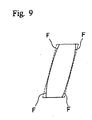
- Crowning F,F,F,F are formed at four parts of every both end parts of tooth surfaces of tooth form of a gear product so that tooth thickness may gradually decrease from the center part thereof toward both ends of tooth, as shown in Fig.9 and tooth surfaces engaging each other may always maintain the point contact thereof.
- a gear product with crowning was manufactured by forming a product having a tooth form without crowning by cutting or forging, and cutting four end parts of tooth surfaces of every tooth so as to form crowning.
- the present invention is based on a technical concept that in a gear product having plurality of tooth formed at a predetermined pitch on an outer peripheral surface of a disc-form body thereof, a crowning is formed at least at one end part of a tooth surface of at least one of gears engaging each other.
- the present invention (the first invention described in Claim 1) provides a gear product having a plurality of tooth profiles formed at a predetermined pitch on an outer peripheral surface of a disc-form body thereof, in which a crowning is formed at least at one end part of a tooth surface of at least one of gears engaging each other.
- the present invention (the second invention described in Claim 2), according to the first invention, provides a gear product in Which the crowning is formed at least at one end part of an upper side tooth surface or a lower side tooth surface of at least one or the other gear.
- the present invention (the third invention described in Claim 3), according to the first invention, provides a gear product in which the crowning is formed at two end parts arbitrarily selected from four end parts of both of an upper side tooth surface and a lower side tooth surface of one or the other gear.
- the present invention (the fourth invention described in Claim 4), according to the first invention, provides a gear product in which the crowning is formed at three end parts arbitrarily selected from four end parts of both of an upper side tooth surface and a lower side tooth surface of one or the other gear.
- the present invention (the fifth invention described in Claim 5), according to the first invention, provides a gear product in which the crowning is formed at an upper end part of an upper side tooth surface of one gear and the crowning is formed at the upper end part and a lower end part of the upper side tooth surface and a lower end part of a lower side tooth surface of the other gear.
- the present invention (the sixth invention described in Claim 6), according to the first invention, provides a gear product in which the crowning is formed at upper and lower end parts of an upper side tooth surface and an upper end part of a lower side tooth surface of one gear, and the crowning is formed at the upper and lower end parts of the upper side tooth surface and a lower end part of the lower side tooth surface of the other gear.
- the present invention (the seventh invention described in Claim 7), according to the first invention, provides a gear product in which the crowning is formed at an upper end part of an upper side tooth surface and a lower end part of a lower side tooth surface of one gear.
- the present invention (the eighth invention described in Claim 8), according to the first invention, provides a gear product in which the crowning is formed at upper and lower end parts of an upper side tooth surface and a lower end part of a lower side tooth surface of one gear and the crowning is formed at the upper end part of the upper side tooth surface and the lower end part of the lower side tooth surface of the other gear.
- the present invention (the ninth invention described in Claim 9), according to the first invention, provides a gear product in which the crowning is formed at a lower end part of an upper side tooth surface and an upper end part of a lower side tooth surface of one gear.
- the present invention (the tenth invention described in Claim 10), according to the first invention, provides a gear product in which the crowning is formed at a lower end part of an upper side tooth surface and an upper end part of a lower side tooth surface of one gear and the crowning is formed at the lower end part of the upper side tooth surface and the upper end part of the lower side tooth surface of the other gear.
- the present invention (the eleventh invention described in Claim 11) provides a technology which enables to reduce machining time for forming a crowning and a technology for forming a crowning by the utilization of forging means, and provides a gear product having a plurality of tooth formed at a predetermined pitch on an outer peripheral surface of a disc-form body thereof, in which tooth forms of all teeth are unified to one pattern selected from a plurality of pattern in which a crowning is formed at at least one of four parts of every both ends on each tooth surface of the teeth and the crowning is not formed at the other of the four parts thereof.
- the present invention provides a gear product in which the selected pattern is one of fourteen patterns comprising four patterns in which the crowning is formed at one of an upper end part or lower end part of a upper inclined surface, and an upper end part or a lower end part of a lower inclined surface, six patterns in which the crownings are formed at two parts such as the upper end part and the lower end part of the upper inclined surface, the upper end part of the upper inclined surface and the upper end part of the lower inclined surface, the upper end part of the upper inclined surface and the lower end part of the lower inclined surface, the lower end part of the upper inclined surface and the upper end part of the lower inclined surface, the lower end part of the upper inclined surface and the lower end part of the lower inclined surface, or the upper end part and lower end part of the lower inclined surface, and four patterns in which the crownings are formed at three parts such as the upper end part and the lower end part of the upper inclined surface and the upper end part of the lower inclined surface, the upper end
- the present invention (the thirteenth invention described in Claim 13), according to any one of the inventions from the first to the twelfth, provides a gear product in which the plurality of tooth formed on the outer peripheral surface of the disc-form part thereof is a helical tooth.
- the present invention provides a method for manufacturing a gear product having a plurality of tooth formed at a predetermined pitch on an outer peripheral surface of a disc-form body thereof, in which a crowning is formed at least at one end part of tooth surface of at least one of gears engaging each other.
- the present invention (the fifteenth invention described in Claim 15), according to the fourteenth invention, provides a method for manufacturing a gear product in which a tooth form having the crowning of a tooth formed on the outer peripheral surface is formed by cutting.
- the present invention (the sixteenth invention described in Claim 16), according to the fourteenth invention, provides a method for manufacturing a gear product in which a tooth form having the crowning of a helical tooth formed on the outer peripheral surface is formed by upsetting on forging.
- the present invention (the seventeenth invention described in Claim 17), according to the fourteenth invention, provides a method for manufacturing a gear product in which a tooth form having the crowning of a helical tooth formed on the outer peripheral surface is formed by ironing on forging.
- the present invention provides a method for manufacturing a gear product in which a first molding having a plurality of tooth, having no crowning, formed at a predetermined pitch on an outer peripheral surface of a disc-form body thereof is cut so that tooth forms of all teeth may be unified to a pattern selected from a plurality of pattern in which the crowning is farmed at at least one of four parts of every both ends on each tooth surface of the teeth and the crowning is not formed at the other of the four parts thereof.
- the present invention provides a method for manufacturing a gear product in which a first molding having a plurality of helical tooth, having no crowning, formed at a predetermined pitch on an outer peripheral surface of a disc-form body thereof is molded by ironing so that the crowning may be formed at a lower part of an upper side tooth surface and an upper part of a lower side tooth surface among four parts of both end parts of tooth surfaces of the all teeth.
- the present invention achieves rationalization by decreasing at least one cutting part in case that the crowning is formed by cutting.
- the present invention has an advantage that there is no need of cutting, it is efficient and there is no dispersion.
- Fig. 1 shows a forming step of the first molded article.
- 1 is a cope
- 2 is a drag
- a mandrel 3 is projected at the center of a pressure surface of the cope 1.
- a cavity 4 which is two-stage form composed of a disc-form like boss forming part 4a for forming a boss and a disc-form gear forming part 4b for forming a gear, is provided in the drag 2.
- a tooth form or profile 5 for forming helical gear is formed on an inner peripheral surface corresponding to the gear forming part 4b and a knockout sleeve 6 is provided on a bottom surface so as to project movably.
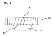
- a first molded article W1 shown in Fig.2 can be took out by push up of the knockout sleeve 6.
- the helical tooth 9 of the first molded article W1 molded in this process has no crowning.
- the cutting process is the same as a conventional cutting process with cutting tools.
- cut parts are not all of the four parts of both end parts on tooth surfaces and a crowning is formed in one pattern selected from fourteen patterns.
- the fourteen patterns comprise four patterns in which the crowning is formed at one of an upper end part A or a lower end part B of an upper inclined surface 91, an upper end part C or a lower end part D of a lower inclined surface 92 (as shown in Fig.3(a)); six patterns in which crownings are formed at two parts such as the upper end part A and the lower end part B of the upper inclined surface 91, the upper end part A of the upper inclined surface 91 and the upper end part C of the lower inclined surface 92, the upper end part A of the upper inclined surface 91 and the lower end part D of the lower inclined surface 92, the lower end part B of the upper inclined surface 91 and the upper end part C of the lower inclined surface 92, the lower end part B of the upper inclined surface 91 and the lower end part D of the lower inclined surface 92, or the upper end part C and the lower end part D of the lower
- crownings are formed at three parts such as the upper end part A and the lower end part B of the upper inclined surface 91 and the upper end part C of the lower inclined surface 92, the upper end part A and the lower end part B of the upper inclined surface 91 and the lower end part D of the lower inclined surface 92, the upper end part A of the upper inclined surface 91 and the upper end part C and the lower end part D of the lower inclined surface 92, or the lower end part B of the upper inclined surface 91 and the upper end part C and the lower end part D of the lower inclined surface 92 (as shown in Fig.3(c)).
- a crowning is formed by upsetting process as a forging process.
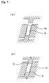
- this upsetting process as shown in Fig.5(a) and Fig.5(b), a helical tooth 9 is depressed in an axial direction in a die 10 for forming a helical tooth.
- a lower part of an upper side surface 91 and an upper part of a lower side surface 92 are strongly depressed on an inner surface of the die 10 for forming a helical tooth.
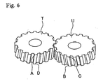
- crownings are formed at the upper part A of the upper side tooth surface 111 and the lower part D of the lower side tooth surface 112 of a helical tooth 11 of the gear shown in Fig.5(b) and the gear T shown in Fig.6.
- crownings formed by upsetting process are formed at parts having left-to-right inverted relationship determined by an inclined direction of a helical tooth. Therefore, in a pair of the gear T and a gear U having crownings formed in reverse patterns with each other, crownings are formed at all of four parts A,B,C,D of a meshing surface of any teeth.
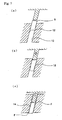
- a helical tooth 9 is ironed along a tooth trace by putting the helical tooth 9 through a die 13 for forming a helical tooth having constrictions formed on an inner surface thereof, as shown in Figs. 7(a)-(c).
- Crownings F,F are formed at a lower part of an upper side tooth surface 141 and the upper part of the lower side tooth surface 142 of a helical tooth 14 by ironing.
- crownings formed by ironing process also are formed at parts having left-to-right inverted relationship determined by an inclined direction of a helical tooth. Therefore, in a pair of the gear V and a gear W having crownings formed in reverse patterns with each other, crownings are formed at all four parts A,B,C,D of a meshing surface of any teeth.
- the crowning is formed in upsetting and ironing process as one of forging processes, there is no need of cutting process, the crowning is formed instantly and there is no dispersion.
- crownings can be formed at any other tooth form except for a helical tooth.
- a gear product having a plurality of tooth formed at a predetermined pitch on an outer peripheral surface of a disc-form body thereof and a method for manufacturing the same, by forming a crowning at least at one end part of a tooth surface of at least one of gears engaging each other, it is able to reduce the trouble of process for forming a crowning, to abbreviate machining time, to reduce the dispersion of accuracy due to abrasion of tools and the wastage cost of tools, to enhance efficiency greatly, and to lower costs.
Landscapes
- Engineering & Computer Science (AREA)
- Mechanical Engineering (AREA)
- General Engineering & Computer Science (AREA)
- Gears, Cams (AREA)
- Forging (AREA)
Applications Claiming Priority (3)
| Application Number | Priority Date | Filing Date | Title |
|---|---|---|---|
| JP2002127352 | 2002-04-26 | ||
| JP2002127352 | 2002-04-26 | ||
| PCT/JP2003/005231 WO2003091604A1 (en) | 2002-04-26 | 2003-04-24 | Gear product and method of manufacturing the gear product |
Publications (3)
| Publication Number | Publication Date |
|---|---|
| EP1500849A1 true EP1500849A1 (de) | 2005-01-26 |
| EP1500849A4 EP1500849A4 (de) | 2006-11-22 |
| EP1500849B1 EP1500849B1 (de) | 2013-07-10 |
Family
ID=29267647
Family Applications (1)
| Application Number | Title | Priority Date | Filing Date |
|---|---|---|---|
| EP03723185.9A Expired - Lifetime EP1500849B1 (de) | 2002-04-26 | 2003-04-24 | Zahnradprodukt |
Country Status (5)
| Country | Link |
|---|---|
| US (1) | US20050278952A1 (de) |
| EP (1) | EP1500849B1 (de) |
| JP (1) | JPWO2003091604A1 (de) |
| CA (1) | CA2483535C (de) |
| WO (1) | WO2003091604A1 (de) |
Cited By (1)
| Publication number | Priority date | Publication date | Assignee | Title |
|---|---|---|---|---|
| EP1938914A1 (de) * | 2006-12-29 | 2008-07-02 | O-OKA Corporation | Vorrichtung und Verfahren zum Endschmieden eines schrägverzahnten Zahnrades und das so hergestellte schrägverzahnte Zahnrad |
Families Citing this family (11)
| Publication number | Priority date | Publication date | Assignee | Title |
|---|---|---|---|---|
| DE112006001989B4 (de) * | 2005-07-28 | 2020-07-30 | Musashi Seimitsu Kogyo K.K. | Verfahren zum Konstruieren eines Zahnrades unter Verwendung eines CAD-Systems |
| JP5184762B2 (ja) * | 2006-06-08 | 2013-04-17 | シロキ工業株式会社 | リクライニング装置 |
| EP2131995B1 (de) * | 2007-04-04 | 2017-06-07 | Gkn Sinter Metals, Llc | Pulvermetallschmiedestück sowie verfahren zu seiner herstellung |
| RU2365460C2 (ru) * | 2007-07-03 | 2009-08-27 | Открытое акционерное общество "Калужский завод автомобильного электрооборудования" | Способ изготовления шестерни стеклоподъемника |
| DE102008048339B4 (de) * | 2008-09-22 | 2016-07-28 | Autoliv Development Ab | Reversibler Gurtstraffer |
| EP2656940B1 (de) | 2011-03-24 | 2018-05-09 | Aisin AW Co., Ltd. | Verfahren zur herstellung einer zahnprofilkomponente |
| JP5626061B2 (ja) * | 2011-03-24 | 2014-11-19 | アイシン・エィ・ダブリュ株式会社 | 歯形部品の製造方法および歯形部品の製造装置 |
| JP5385422B2 (ja) * | 2012-05-07 | 2014-01-08 | シロキ工業株式会社 | リクライニング装置 |
| US9403207B2 (en) * | 2014-11-25 | 2016-08-02 | Metal Industries Research And Development Centre | Spiral bevel gear forging apparatus |
| DE102017008674A1 (de) * | 2017-09-15 | 2019-03-21 | Rolls-Royce Deutschland Ltd & Co Kg | Planetengetriebe |
| JP7165081B2 (ja) * | 2019-03-18 | 2022-11-02 | Ntn株式会社 | インホイールモータ駆動装置 |
Family Cites Families (9)
| Publication number | Priority date | Publication date | Assignee | Title |
|---|---|---|---|---|
| US2346266A (en) * | 1941-04-21 | 1944-04-11 | Nat Broach & Mach | Gear crowning |
| JPH0369844A (ja) | 1989-08-07 | 1991-03-26 | Hitachi Powdered Metals Co Ltd | 歯車 |
| US5341699A (en) * | 1993-04-06 | 1994-08-30 | Axicon Gear Company | Zero dynamic increment gearing |
| JP3375041B2 (ja) * | 1996-08-06 | 2003-02-10 | 日産自動車株式会社 | 歯車の成形方法および成形装置 |
| JP3494349B2 (ja) * | 1998-04-20 | 2004-02-09 | 大岡技研株式会社 | ヘリカルギヤの製造方法 |
| DE50006701D1 (de) * | 1999-12-01 | 2004-07-08 | Lambert Ag Safnern | Formschneidverfahren für geradverzahnte kegelräder |
| JP2001340933A (ja) * | 2000-05-29 | 2001-12-11 | Toyota Motor Corp | 歯車の製造方法 |
| US7195578B2 (en) * | 2004-12-03 | 2007-03-27 | Axiom Automotive Technologies, Inc. | Automatic transmission and gear train |
| JP2007024296A (ja) * | 2005-07-21 | 2007-02-01 | Kyocera Mita Corp | 歯車および歯車機構 |
-
2003
- 2003-04-24 EP EP03723185.9A patent/EP1500849B1/de not_active Expired - Lifetime
- 2003-04-24 WO PCT/JP2003/005231 patent/WO2003091604A1/ja not_active Ceased
- 2003-04-24 US US10/511,446 patent/US20050278952A1/en not_active Abandoned
- 2003-04-24 JP JP2003588109A patent/JPWO2003091604A1/ja active Pending
- 2003-04-24 CA CA002483535A patent/CA2483535C/en not_active Expired - Lifetime
Non-Patent Citations (2)
| Title |
|---|
| No further relevant documents disclosed * |
| See also references of WO03091604A1 * |
Cited By (2)
| Publication number | Priority date | Publication date | Assignee | Title |
|---|---|---|---|---|
| EP1938914A1 (de) * | 2006-12-29 | 2008-07-02 | O-OKA Corporation | Vorrichtung und Verfahren zum Endschmieden eines schrägverzahnten Zahnrades und das so hergestellte schrägverzahnte Zahnrad |
| US8196488B2 (en) | 2006-12-29 | 2012-06-12 | O-Oka Corporation | Gear |
Also Published As
| Publication number | Publication date |
|---|---|
| WO2003091604A1 (en) | 2003-11-06 |
| EP1500849B1 (de) | 2013-07-10 |
| US20050278952A1 (en) | 2005-12-22 |
| CA2483535C (en) | 2009-06-02 |
| CA2483535A1 (en) | 2003-11-06 |
| JPWO2003091604A1 (ja) | 2005-09-02 |
| EP1500849A4 (de) | 2006-11-22 |
Similar Documents
| Publication | Publication Date | Title |
|---|---|---|
| US20050278952A1 (en) | Gear product and method for manufacturing the same | |
| JP3759419B2 (ja) | 軸付きパーキングギヤ及びその軸付きパーキングギヤの製造方法 | |
| KR20200052252A (ko) | 스탬핑된 부품을 제조하기 위한 방법 | |
| US7007536B2 (en) | Synchronizer sleeve used in power transmission and press-forming apparatus for the same | |
| JPS61502736A (ja) | 鍛造方法 | |
| JP2005118789A (ja) | ボス付き歯車状部材の成形方法及びボス付き歯車状部材 | |
| JP2017074600A (ja) | 座金付きナットの製造方法 | |
| CN100594082C (zh) | 烧结离合器盘毂 | |
| JP2010042440A (ja) | 溝付きボルトの製造方法 | |
| JP3583614B2 (ja) | 歯車の製造方法 | |
| JPH0249817B2 (de) | ||
| US20040231447A1 (en) | Gear, and method and apparatus for manufacturing the same | |
| CN104136144A (zh) | 用于形成链轮的方法 | |
| KR100573379B1 (ko) | 2단 기어의 제조방법 | |
| JP6252806B2 (ja) | ロックパウルの製造方法及び非対称部品の製造方法 | |
| JP4217913B2 (ja) | 段付きギヤの製造方法 | |
| JPH064991Y2 (ja) | プレス加工装置 | |
| JPS58122145A (ja) | 歯車の鍛造方法 | |
| JP2009156369A (ja) | 二段ヘリカル歯車 | |
| JP4614260B2 (ja) | ドッグクラッチ穴付き変速用歯車の製造方法 | |
| JP5860223B2 (ja) | 難加工形状を具えた厚肉金属部品の製造方法 | |
| JP4907811B2 (ja) | クラッチギヤの面取り加工方法 | |
| JP4638302B2 (ja) | 冷間鍛造傘歯車 | |
| JP5951947B2 (ja) | 複数の歯を具備する機械コンポーネントのブランク、および、機械コンポーネントの製造方法 | |
| JP2024135501A (ja) | 歯車素材 |
Legal Events
| Date | Code | Title | Description |
|---|---|---|---|
| PUAI | Public reference made under article 153(3) epc to a published international application that has entered the european phase |
Free format text: ORIGINAL CODE: 0009012 |
|
| 17P | Request for examination filed |
Effective date: 20041104 |
|
| AK | Designated contracting states |
Kind code of ref document: A1 Designated state(s): AT BE BG CH CY CZ DE DK EE ES FI FR GB GR HU IE IT LI LU MC NL PT RO SE SI SK TR |
|
| A4 | Supplementary search report drawn up and despatched |
Effective date: 20061019 |
|
| 17Q | First examination report despatched |
Effective date: 20090113 |
|
| RAP1 | Party data changed (applicant data changed or rights of an application transferred) |
Owner name: O-OKA CORPORATION |
|
| RIN1 | Information on inventor provided before grant (corrected) |
Inventor name: OOKA, JUNICHI |
|
| GRAP | Despatch of communication of intention to grant a patent |
Free format text: ORIGINAL CODE: EPIDOSNIGR1 |
|
| GRAS | Grant fee paid |
Free format text: ORIGINAL CODE: EPIDOSNIGR3 |
|
| GRAA | (expected) grant |
Free format text: ORIGINAL CODE: 0009210 |
|
| AK | Designated contracting states |
Kind code of ref document: B1 Designated state(s): DE FR GB IT |
|
| REG | Reference to a national code |
Ref country code: GB Ref legal event code: FG4D |
|
| REG | Reference to a national code |
Ref country code: DE Ref legal event code: R096 Ref document number: 60344465 Country of ref document: DE Effective date: 20130829 |
|
| PLBE | No opposition filed within time limit |
Free format text: ORIGINAL CODE: 0009261 |
|
| STAA | Information on the status of an ep patent application or granted ep patent |
Free format text: STATUS: NO OPPOSITION FILED WITHIN TIME LIMIT |
|
| 26N | No opposition filed |
Effective date: 20140411 |
|
| REG | Reference to a national code |
Ref country code: DE Ref legal event code: R097 Ref document number: 60344465 Country of ref document: DE Effective date: 20140411 |
|
| REG | Reference to a national code |
Ref country code: FR Ref legal event code: PLFP Year of fee payment: 14 |
|
| REG | Reference to a national code |
Ref country code: FR Ref legal event code: PLFP Year of fee payment: 15 |
|
| REG | Reference to a national code |
Ref country code: FR Ref legal event code: PLFP Year of fee payment: 16 |
|
| PGFP | Annual fee paid to national office [announced via postgrant information from national office to epo] |
Ref country code: IT Payment date: 20210310 Year of fee payment: 19 Ref country code: FR Payment date: 20210309 Year of fee payment: 19 |
|
| PGFP | Annual fee paid to national office [announced via postgrant information from national office to epo] |
Ref country code: GB Payment date: 20210331 Year of fee payment: 19 |
|
| PGFP | Annual fee paid to national office [announced via postgrant information from national office to epo] |
Ref country code: DE Payment date: 20210330 Year of fee payment: 19 |
|
| REG | Reference to a national code |
Ref country code: DE Ref legal event code: R119 Ref document number: 60344465 Country of ref document: DE |
|
| GBPC | Gb: european patent ceased through non-payment of renewal fee |
Effective date: 20220424 |
|
| PG25 | Lapsed in a contracting state [announced via postgrant information from national office to epo] |
Ref country code: GB Free format text: LAPSE BECAUSE OF NON-PAYMENT OF DUE FEES Effective date: 20220424 Ref country code: FR Free format text: LAPSE BECAUSE OF NON-PAYMENT OF DUE FEES Effective date: 20220430 Ref country code: DE Free format text: LAPSE BECAUSE OF NON-PAYMENT OF DUE FEES Effective date: 20221103 |
|
| PG25 | Lapsed in a contracting state [announced via postgrant information from national office to epo] |
Ref country code: IT Free format text: LAPSE BECAUSE OF NON-PAYMENT OF DUE FEES Effective date: 20220424 |