EP1498333A2 - Hydraulisches Bremsystem für eine Kraftfahrzeugen - Google Patents
Hydraulisches Bremsystem für eine Kraftfahrzeugen Download PDFInfo
- Publication number
- EP1498333A2 EP1498333A2 EP04019627A EP04019627A EP1498333A2 EP 1498333 A2 EP1498333 A2 EP 1498333A2 EP 04019627 A EP04019627 A EP 04019627A EP 04019627 A EP04019627 A EP 04019627A EP 1498333 A2 EP1498333 A2 EP 1498333A2
- Authority
- EP
- European Patent Office
- Prior art keywords
- pressure
- valve
- fluid
- brake
- pump
- Prior art date
- Legal status (The legal status is an assumption and is not a legal conclusion. Google has not performed a legal analysis and makes no representation as to the accuracy of the status listed.)
- Granted
Links
Images


Classifications
-
- B—PERFORMING OPERATIONS; TRANSPORTING
- B60—VEHICLES IN GENERAL
- B60T—VEHICLE BRAKE CONTROL SYSTEMS OR PARTS THEREOF; BRAKE CONTROL SYSTEMS OR PARTS THEREOF, IN GENERAL; ARRANGEMENT OF BRAKING ELEMENTS ON VEHICLES IN GENERAL; PORTABLE DEVICES FOR PREVENTING UNWANTED MOVEMENT OF VEHICLES; VEHICLE MODIFICATIONS TO FACILITATE COOLING OF BRAKES
- B60T8/00—Arrangements for adjusting wheel-braking force to meet varying vehicular or ground-surface conditions, e.g. limiting or varying distribution of braking force
- B60T8/32—Arrangements for adjusting wheel-braking force to meet varying vehicular or ground-surface conditions, e.g. limiting or varying distribution of braking force responsive to a speed condition, e.g. acceleration or deceleration
- B60T8/34—Arrangements for adjusting wheel-braking force to meet varying vehicular or ground-surface conditions, e.g. limiting or varying distribution of braking force responsive to a speed condition, e.g. acceleration or deceleration having a fluid pressure regulator responsive to a speed condition
- B60T8/40—Arrangements for adjusting wheel-braking force to meet varying vehicular or ground-surface conditions, e.g. limiting or varying distribution of braking force responsive to a speed condition, e.g. acceleration or deceleration having a fluid pressure regulator responsive to a speed condition comprising an additional fluid circuit including fluid pressurising means for modifying the pressure of the braking fluid, e.g. including wheel driven pumps for detecting a speed condition, or pumps which are controlled by means independent of the braking system
- B60T8/4072—Systems in which a driver input signal is used as a control signal for the additional fluid circuit which is normally used for braking
- B60T8/4081—Systems with stroke simulating devices for driver input
-
- B—PERFORMING OPERATIONS; TRANSPORTING
- B60—VEHICLES IN GENERAL
- B60T—VEHICLE BRAKE CONTROL SYSTEMS OR PARTS THEREOF; BRAKE CONTROL SYSTEMS OR PARTS THEREOF, IN GENERAL; ARRANGEMENT OF BRAKING ELEMENTS ON VEHICLES IN GENERAL; PORTABLE DEVICES FOR PREVENTING UNWANTED MOVEMENT OF VEHICLES; VEHICLE MODIFICATIONS TO FACILITATE COOLING OF BRAKES
- B60T13/00—Transmitting braking action from initiating means to ultimate brake actuator with power assistance or drive; Brake systems incorporating such transmitting means, e.g. air-pressure brake systems
- B60T13/10—Transmitting braking action from initiating means to ultimate brake actuator with power assistance or drive; Brake systems incorporating such transmitting means, e.g. air-pressure brake systems with fluid assistance, drive, or release
- B60T13/66—Electrical control in fluid-pressure brake systems
- B60T13/68—Electrical control in fluid-pressure brake systems by electrically-controlled valves
- B60T13/686—Electrical control in fluid-pressure brake systems by electrically-controlled valves in hydraulic systems or parts thereof
-
- B—PERFORMING OPERATIONS; TRANSPORTING
- B60—VEHICLES IN GENERAL
- B60T—VEHICLE BRAKE CONTROL SYSTEMS OR PARTS THEREOF; BRAKE CONTROL SYSTEMS OR PARTS THEREOF, IN GENERAL; ARRANGEMENT OF BRAKING ELEMENTS ON VEHICLES IN GENERAL; PORTABLE DEVICES FOR PREVENTING UNWANTED MOVEMENT OF VEHICLES; VEHICLE MODIFICATIONS TO FACILITATE COOLING OF BRAKES
- B60T7/00—Brake-action initiating means
- B60T7/02—Brake-action initiating means for personal initiation
- B60T7/04—Brake-action initiating means for personal initiation foot actuated
- B60T7/042—Brake-action initiating means for personal initiation foot actuated by electrical means, e.g. using travel or force sensors
Definitions
- This invention relates to an improved automotive hydraulic pressure brake system in which brake fluid pressure is ordinarily supplied from a pump as a main pressure source, but additional fluid pressure is supplied from a master cylinder when it is necessary to increase brake pressure at a rapid pace, such as for quick brake, at low temperature causing high brake fluid viscosity and upon pump performance degradation.
- the brake system disclosed in Japanese patent 2590825 has, besides a master cylinder for generating fluid pressure when a brake pedal is depressed, a fluid pressure source comprising a pump and an accumulator for supplying fluid pressure to the wheel cylinders in proportion to or independently of how much the brake pedal is depressed. But since such a system needs a bulky accumulator, it is difficult to mount the entire system in an engine room.
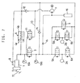
- FIG. 7 is a basic circuit diagram of such a brake system. As shown, in lines connecting the master cylinder 1 to wheel cylinders 2A, 2B (letters A, B are sometimes omitted hereinbelow), an electromagnetic on-off valve 3 and a stroke simulator 4 are provided.
- This brake system further includes control valves (comprising pressure-increasing on-off valves 5A, 5B and pressure-reducing on-off valves 6A, 6B in this example) for controlling the wheel cylinder pressure based on command from an electronic control unit (ECU, not shown), an on-off valve 9 provided in a return line extending from the discharge port of a pump 7 (a hydraulic pump in this example) to a reservoir 8, a bypass 10 connecting the master cylinder 1 to the suction port of the pump 7, an on-off valve 11 provided in the bypass 10, and a check valve 12 provided in the return line to check a fluid flow from the bypass 10 to the reservoir 8.
- the on-off valves 5 and 6, which are used for antilock control, are not essential elements in this arrangement.
- This brake system is also provided with fluid pressure sensors 13A, 13B, a relief valve 14 for preventing overpressure, a silencing throttle 15 and a silencer 16.
- Relief valve 14, throttle 15 and silencer 16 are used in this arrangement but are not essential elements.
- the stroke simulator 4 has its back-pressure chamber 4b connected to the reservoir 8 to keep the chamber wet. It has a main chamber 4a.
- Fluid pressure can be supplied from the master cylinder by opening the on-off valve 3. But when it is repeatedly opened and closed, pulsation occurs in the brake lines. It also occurs while the pump 7 is activated. Such pulsation is transmitted to the brake pedal, thus impairing the brake feeling. If the on-off valve 3 is kept open, the brake pedal will kick back when the wheel cylinder pressure exceeds the master cylinder pressure (that is, fluid pressure produced in the master cylinder).
- the brake system of Fig. 7 has the bypass 10 provided with the on-off valve 11 to supply fluid pressure from the master cylinder 1 via the pump 7.
- this modification posed another problem. That is, since the on-off valve 11 has to be opened in order to rapidly increase pressure, the check valve 12 is closed, so that fluid cannot be supplied to the pump 7 from the reservoir 8. Thus, a large amount of fluid has to be supplied from the master cylinder. This significantly increases the stroke of the brake pedal 17 compared with when the on-off valve 11 is closed for increase in the brake pressure at a moderate rate.
- valve 11 While the valve 11 is open for rapid pressure increase, the pump sucks fluid discontinuously from the master cylinder. Pulsation in the brake lines is thus directly transferred to the brake pedal.
- the throttle 15 provided at the discharge side of the pump will suppress pulsation and noise, it makes it difficult to increase fluid pressure at a rapid rate.
- An object of this invention is to provide a hydraulic pressure brake system that can eliminate a delay in the pressure rise during a rapid pressure increase and worsening of the pedal feeling, and in which the responsiveness is improved by increasing the suction efficiency of the pump during a rapid pressure increase or at a low temperature.
- an automotive hydraulic pressure brake system comprising a master cylinder for producing fluid pressure corresponding to a force applied to a brake pedal, a reservoir, wheel cylinders, a power pump having an inlet port connected to the reservoir, an on-off valve provided in a fluid line connecting the master cylinder to the wheel cylinders, the on-off valve being closed to supply brake fluid pressure to the wheel cylinders from the pump while an electric control unit of the system is functioning normally, characterised in that a bypass communicating the master cylinder to the wheel brake cylinders while bypassing the on-off valve is provided, and a check valve or a relief valve for allowing only a fluid flow from the master cylinder toward the wheel brake cylinders, and a shut-off valve are provided in the bypass.
- a bypass communicating the master cylinder to the wheel brake cylinders while bypassing the on-off valve is provided, and a check valve or a relief valve for allowing only a fluid flow from the master cylinder toward the wheel brake cylinders, and a shut-off valve are provided in the bypass
- an automotive fluid pressure brake system comprising a master cylinder for producing fluid pressure corresponding to a force applied to a brake pedal, a reservoir, wheel cylinders, a power pump having an inlet port connected to the reservoir, an on-off valve provided in a fluid line connecting the master cylinder to the wheel cylinders, a stroke simulator having a main chamber communicating with a line connecting the master cylinder to the on-off valve and a back-pressure chamber communicating with the reservoir, the on-off valve being closed to supply brake fluid pressure to the wheel brake cylinders from the pump while an electric control unit of the system is functioning normally, characterized in that a throttle is provided in a circuit connecting the back-pressure chamber of the stroke simulator to the reservoir, that the system further comprises a first suction passage extending from a circuit between the throttle and the back-pressure chamber to the suction port of the pump, and a second suction passage communicating the reservoir with the first suction passage, and a check valve provided in the second suction passage to allow only a fluid flow from
- this system is a third embodiment.
- a throttle 15 is provided in the systems of the first and third embodiments on the discharge side of the pump, the bypass is preferably provided in a circuit between the throttle and the wheel cylinders.
- the ECU opens the shut-off valve in the bypass to supply master cylinder pressure through the bypass to the wheel cylinders. In addition to that, the entire fluid sucked by the pump from the reservoir is supplied to the wheel cylinders, so that delay in the pressure increase is minimized.
- a relief valve which opens when a predetermined differential pressure is produced, is used instead of a check valve, pulsation due to activation of the pump will be less liable to be transferred. This further improves the pedal feeling.
- the throttle provided between the back-pressure chamber and the reservoir, the higher the viscosity of brake fluid, and the sharper the depressing of the brake pedal and thus the larger the amount of discharged flow from the back-pressure chamber per unit time, the larger the fluid pressure in the circuit upstream of the throttle.
- the circuit upstream of the throttle is connected to the suction port of the pump through the first suction passage.
- the stroke simulator If a fluid amount amplifier is used as the stroke simulator, the amount of fluid discharged from the back-pressure chamber increases above the amount of fluid flowing into the main chamber, so that the suction efficiency of the pump further improves. This further reduces the stroke of the pedal.
- the brake system of the third embodiment exhibits the functions and effects of both of the systems of the first and second embodiments, so that the pressure increase is faster.
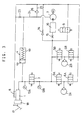
- Fig. 1 shows an automotive hydraulic pressure brake system of the first embodiment.
- Two brake fluid circuits are usually separately mounted on a vehicle, each for two of the four wheel brake cylinders.
- Fig. 1 shows one of two circuits.
- the wheel brake cylinders 2A, 2B shown may be for the front right and left wheels, rear right and left wheels, front left and rear right wheels, or front right and rear left wheels.
- the master cylinder pressure which depends on the force applied to the brake pedal 17 by the driver, is directly supplied to the wheel cylinders if the electric control system fails.
- a booster 18 proportionally amplifies the master cylinder pressure so that a sufficient brake pressure can be produced with a small effort on the part of the driver even in such a case.
- Check valves are provided at the discharge and suction sides of the pump 7 to prevent reverse flow of fluid to the reservoir 8 and reverse flow from the wheel cylinder 2 to the pump 7, respectively. In the embodiment shown, such check valves are not shown.
- a bypass 19 is provided to connect the master cylinder 1 to the wheel cylinders 2 while bypassing the on-off valve 3, and instead of the on-off valve 11, a check valve 20 that permits only a fluid flow from the master cylinder 1 to the wheel cylinders 2 and a shut-off valve 21 (such as an electromagnetic on-off valve as shown) are provided in the bypass 19.
- the system of Fig. 1 differs from that of Fig. 7 in these points.
- the ECU closes the on-off valve 3 and activates the pump 7 based on the signal from a brake switch (not shown) and/or a pressure sensor 13A.
- brake pressure can be controlled in proportion to the force applied to the brake pedal by adjusting the amount of fluid supplied from the pump 7 to the wheel cylinders without the need to directly supply master cylinder pressure to the wheel cylinders.
- the vehicle can be braked according to the intention of the driver.
- the pump 7 is initially operated at high speed with the on-off valve 9 in the return line closed. Since the on-off valve 3 in the line to the master cylinder 1 is also closed in this state, all fluid from the pump 7 is supplied to the wheel cylinders 2, so that the brake fluid pressure rises quickly.
- the ECU will slow down or stop the pump 7 and open the on-off valve 9 if necessary.
- the ECU will judge that the pump 7 alone cannot increase brake pressure to the required level, and open the shut-off valve 21 in the bypass 19 to supply brake fluid from the master cylinder 1 directly to the wheel cylinders 2 to prevent delay in pressure increase.
- the ECU will stop the pump and open the on-off valve 9 to return the fluid pressure in the wheel cylinders 2 to the reservoir 8.
- the on-off valves 5 and 6 are provided for antilock control, if necessary, the on-off valve 6 may be opened to return the fluid pressure to the reservoir more quickly to speed up the pressure decrease. Also, in the low-pressure range the on-off valve 3 may be opened to return part of the fluid to the master cylinder 1. It is preferable that as the valve 9, a current-proportional flow control valve (linear valve) is used.
- the amount of fluid supplied to the wheel cylinders 2 can be controlled to a value corresponding to the pedal depressing force by e.g. adjusting the revolving speed of the pump 7 or the torque of the pump driving motor and/or by opening and closing the on-off valves 6 and 9 based on the force applied to the brake pedal by the driver and the wheel cylinder pressure as measured by the pressure sensor 13B. Also, by adjusting the opening of the on-off valves 9 and 6 in one of the two brake systems mounted on the vehicle to a different degree from the valves 9, 6 in the other system, it is possible to apply different brake pressures to the wheel cylinders in the respective systems.
- the ECU determines whether the pump 7 alone can or cannot increase fluid pressure at a required speed based on the rate of change of the force applied to the brake pedal or change in the master cylinder pressure (it exceeds a predetermined value during panic braking), or based on the difference between the readings on the pressure sensors 13A and 13B. If the ECU determines so, it will open the shut-off valve 21 to increase brake pressure with higher response in the above-described manner.
- the ECU is ordinarily programmed to close the shut-off valve 21 when the wheel cylinder pressure has increased to a required level by comparing the values of the pressure sensors 13A, 13B. But even if the shut-off valve 21 is kept open, the brake pedal would not kick back because the check valve 20 in the bypass 19 prevents reverse fluid flow.
- the brake system of Fig. 1 is provided with on-off valves 5, 6 and 9 for controlling the wheel cylinder pressure and pressure sensors 13A and 13B for detecting the master cylinder pressure and the fluid pressure at the discharge side of the pump, respectively.
- this brake system can perform various controls as listed below:
- the check valve 20 in Fig. 1 may be replaced with a relief valve 22 shown in Fig. 2 because the latter is kept closed until the difference in fluid pressure on master cylinder side and pump side exceeds a predetermined value (e.g. 10 bar) and thus can more effectively suppress transmission of pulsation to the brake pedal than a check valve which reacts pressure change sensitively.
- a predetermined value e.g. 10 bar
- the use of a relief valve further improves the pedal feeling upon sharp pressure increase.
- shut-off valve 21 may be omitted by setting the valve-opening differential pressure for the relief valve at a relatively large value (e.g. 20 bar or over).
- the bypass 19 is preferably connected to the circuit nearer to the wheel cylinders than the throttle.
- the on-off valve 3 may be controlled by a signal from a brake switch and/or the pressure sensor 13A, a signal from a stroke sensor for detecting the stroke of the brake pedal may be used.
- Fig. 3 is a circuit diagram of the brake system of the second embodiment.
- a throttle 23 is provided in the circuit connecting the back-pressure chamber 4b of the stroke simulator 4 to the reservoir 8. Also, a first suction passage 24 extending from a point between the throttle 23 and the back-pressure chamber 4b to the suction port of the pump 7, and a second suction passage 25 for communicating the reservoir 8 with the first suction passage 24 are provided, and a check valve that allows only a fluid flow from the reservoir 8 toward the pump 7 is provided in the second suction passage 24. In these points, it differs from the brake system of Fig. 7.
- the check valve 26 in the second suction passage 25 will open, so that fluid will be sucked by the pump 7 from the reservoir 8.
- the system of Fig. 7 determines whether or not the discharge amount of the pump is insufficient based on whether or not the rate of change in the operating force by the driver or the master cylinder has exceeded a predetermined value (in the case of sharp braking, the rate of change is large), and it was necessary to open the on-off valve 11 if the discharge amount of the pump is judged to be insufficient.
- the system of Fig. 3 needs no such function. It is only necessary to suitably design the degree of opening of the throttle 23. It is easier to control.
- the operation at the end of braking is also the same as in the system of Fig. 1.
- the brake system of Fig. 3 too, by providing a brake switch, an electronic control unit and wheel speed sensors, it is possible to perform various controls 1) to 4) and 6) among the above-listed control types.
- Figs. 4A, 4B show specific examples of the stroke simulator 4.
- Fig. 4A shows one in which the main chamber 4a communicating with the master cylinder 1, and the back-pressure chamber 4b communicating with the reservoir 8 are partitioned by a piston 4d biased by a spring 4c.
- Fig. 4B shows one in which the main chamber 4a and the back-pressure chamber 4b are partitioned by a stretchable bellows piston 4e to impart a tredding reaction force to the brake pedal using the resilient restoring force of the bellows piston 4e.
- the position of the main chamber 4a and the back-pressure chamber 4b may be reversed. Any other stroke simulator may also be employed.
- Fig. 5 is a specific example of the stroke simulator having a fluid amount amplifying function.
- the main chamber 4a and the back-pressure chamber 4b are partitioned by a different-diameter piston 4f biased by a spring 4c.
- Fluid amount is amplified in proportion to the ratio between the pressure-receiving surface areas at both ends of the different-diameter piston 4f.
- the amplified fluid amount is supplied into the pump, so that it is possible to further reduce the push-in of the brake pedal.
- Fig. 6 is a circuit diagram of the brake system of the third embodiment.
- a bypass 19 is provided to communicate the master cylinder 1 and the wheel cylinders 2 with each other while bypassing the on-off valve 3, and a check valve 20 that permits only a fluid flow from the master cylinder 1 toward the wheel cylinders 2 and a shut-off valve 21 (an electromagneticall y driven on-off valve in the figure) are provided in the bypass 19.
- a throttle 23 in the circuit connecting the back-pressure chamber 4b of the stroke simulator 4 to the reservoir 8 a first suction passage 24 extending from a point between the throttle 23 and the back-pressure chamber 4b to the suction port of the pump 7, a second suction passage 25 that communicates the reservoir 8 with the first suction passage 24, and a check valve 26 that permits only a fluid flow from the reservoir 8 toward the pump 7 in the second suction passage 25.
- This system is a combination of the system of Fig. 1 and that of Fig. 3. Thus, it reveals both of the functions and effects of the system of Fig. 1 and those of the system of Fig. 3.
- the throttle 23 works to feed fluid discharged from the stroke simulator 4 into the pump 7, and the bypass 19 also opens.
- fluid from the master cylinder 1 is added to the entire amount of discharged fluid from the pump 7, of which the suction efficiency has increased, and is supplied to the wheel cylinders 2.
- a pressure rise of the wheel cylinders 2 is further sped up and the response improves.
- the brake system of Fig. 6 can perform various controls.
- a relief valve which opens when a predetermined fluid pressure difference is produced, is used as the check valve 20, it is possible to further reduce the chance of pulsation produced by the pump being transmitted to the brake pedal.
- the stroke simulator if one in which the amount of discharged fluid from the back-pressure chamber 4b is amplified relative to the amount of fluid from the master cylinder 1, which is introduced into the main chamber 4a, (the fluid amount can be amplified by use of the amplifier of Fig. 5 or a known fluid amount amplifier) is used, the suction efficiency of the pump further increases and the amount of fluid replenishment from the master cylinder decreases. Thus, it is possible to further reduce the push-in of the brake pedal.
- brake fluid replenished from the master cylinder to the wheel cylinders is introduced to the discharge side of the pump through the bypass having a check valve and a shut-off valve.
- discharge resistance is applied by an inexpensive throttle to brake fluid discharged from the back-pressure chamber of a stroke simulator toward the reservoir, and the pump sucks up brake fluid, of which pressure has been increased by the throttle.
- the suction efficiency of the pump improves. This makes it possible to economically avoid a delay in the pressure rise during a rapid pressure increase or at a low temperature.
- the invention according to a first aspect provides an automotive hydraulic pressure brake system comprising a master cylinder (1) for producing fluid pressure corresponding to a force applied to a brake pedal (17), a reservoir (8), wheel cylinders (2A,2B), a power pump (7) having an inlet port connected to said reservoir (8), an on-off valve (3) provided in a fluid line connecting said master cylinder (1) to said wheel cylinders (2A,2B), said on-off valve (3) being closed to supply brake fluid pressure to said wheel brake cylinders (2A,2B) from said pump (7) while an electric control unit of the system is functioning normally, whereby a bypass (19) communicating said master cylinder (1) to said wheel brake cylinders (2A,2B) while bypassing said on-off valve (3) is provided, and a check valve (20) or a relief valve (22) for allowing only a fluid flow from said master cylinder (1) toward said wheel brake cylinders (2A,2B), and a shut-off valve (21) are provided in said bypass (19).
- the invention provides an automotive hydraulic pressure brake system comprising a master cylinder (1) for producing fluid pressure corresponding to a force applied to a brake pedal (17), a reservoir (8), wheel cylinders (2A,2B), a power pump (7) having an inlet port connected to said reservoir (8), an on-off valve (3) provided in a fluid line connecting said master cylinder (1) to said wheel cylinders (2A,2B), a stroke simulator (4) having a main chamber (4a) communicating with a line connecting said master cylinder (1) to said on-off valve (3) and a back-pressure chamber (4b) communicating with said reservoir (8), said on-off valve (3) being closed to supply brake fluid pressure to said wheel brake cylinders (2A,2B) from said pump (7) while an electric control unit of the system is functioning normally whereby a throttle (23) is provided in a circuit connecting said back-pressure chamber (46) of said stroke simulator (4) to said reservoir (8), that said system further comprises a first suction passage (24) extending from a circuit between said throttle (23) and
- the automotive hydraulic pressure brake of the second aspect can be improved, if a bypass (19) communicating said master cylinder (1) to said wheel brake cylinders (2A,2B) while bypassing said on-off valve (3) is provided, and a check valve (20) or a relief valve (22) for allowing only a fluid flow from said master cylinder (1) toward said wheel brake cylinders (2A,2B), and a shut-off valve (21) are provided in said bypass (19).
- the automotive hydraulic pressure brake system of the first or third aspect can be improved, if a throttle (15) is provided in a circuit on the discharge side of said pump (7), said bypass (19) having one end communicating with a circuit connecting said throttle (15) and said wheel cylinders (2A,2B).
- the automotive hydraulic pressure brake system of the second or third aspect can be improved, if a fluid amount amplifier is used as said stroke simulator (4) to amplify the amount of fluid flowing out of said back-pressure chamber (4b) of said stroke simulator (4) relative to the amount of fluid flowing into said main chamber (4a) of said stroke simulator (4).
Applications Claiming Priority (13)
| Application Number | Priority Date | Filing Date | Title |
|---|---|---|---|
| JP33249599 | 1999-11-24 | ||
| JP33249599 | 1999-11-24 | ||
| JP33266099 | 1999-11-24 | ||
| JP33266099 | 1999-11-24 | ||
| JP33265299 | 1999-11-24 | ||
| JP33265299 | 1999-11-24 | ||
| JP2000256697 | 2000-08-28 | ||
| JP2000256763 | 2000-08-28 | ||
| JP2000256682 | 2000-08-28 | ||
| JP2000256763A JP2001213296A (ja) | 1999-11-24 | 2000-08-28 | 車両用液圧ブレーキ装置 |
| JP2000256697A JP2001213295A (ja) | 1999-11-24 | 2000-08-28 | 車両用液圧ブレーキ装置 |
| JP2000256682A JP2001213294A (ja) | 1999-11-24 | 2000-08-28 | 車両用液圧ブレーキ装置 |
| EP00125695A EP1103436B1 (de) | 1999-11-24 | 2000-11-23 | Hydraulisches Bremsdrucksystem für Kraftfahrzeuge |
Related Parent Applications (1)
| Application Number | Title | Priority Date | Filing Date |
|---|---|---|---|
| EP00125695A Division EP1103436B1 (de) | 1999-11-24 | 2000-11-23 | Hydraulisches Bremsdrucksystem für Kraftfahrzeuge |
Publications (3)
| Publication Number | Publication Date |
|---|---|
| EP1498333A2 true EP1498333A2 (de) | 2005-01-19 |
| EP1498333A3 EP1498333A3 (de) | 2005-05-11 |
| EP1498333B1 EP1498333B1 (de) | 2007-01-31 |
Family
ID=27554632
Family Applications (2)
| Application Number | Title | Priority Date | Filing Date |
|---|---|---|---|
| EP00125695A Expired - Lifetime EP1103436B1 (de) | 1999-11-24 | 2000-11-23 | Hydraulisches Bremsdrucksystem für Kraftfahrzeuge |
| EP04019627A Expired - Lifetime EP1498333B1 (de) | 1999-11-24 | 2000-11-23 | Hydraulisches Bremsystem für eine Kraftfahrzeugen |
Family Applications Before (1)
| Application Number | Title | Priority Date | Filing Date |
|---|---|---|---|
| EP00125695A Expired - Lifetime EP1103436B1 (de) | 1999-11-24 | 2000-11-23 | Hydraulisches Bremsdrucksystem für Kraftfahrzeuge |
Country Status (3)
| Country | Link |
|---|---|
| US (1) | US6464307B1 (de) |
| EP (2) | EP1103436B1 (de) |
| DE (2) | DE60033245T2 (de) |
Cited By (4)
| Publication number | Priority date | Publication date | Assignee | Title |
|---|---|---|---|---|
| CN100577486C (zh) * | 2004-09-03 | 2010-01-06 | 克诺尔布莱姆斯商用车制动系统有限公司 | 拖车制动系统 |
| US7983827B2 (en) | 2006-11-16 | 2011-07-19 | Hitachi, Ltd. | Brake control apparatus |
| CN108944871A (zh) * | 2017-05-26 | 2018-12-07 | 丰田自动车株式会社 | 液压制动装置 |
| DE102022204332B3 (de) | 2022-05-02 | 2023-08-24 | Volkswagen Aktiengesellschaft | Bremssystem mit Bypassleitung und Kraftfahrzeug |
Families Citing this family (44)
| Publication number | Priority date | Publication date | Assignee | Title |
|---|---|---|---|---|
| WO2002064409A2 (de) * | 2001-02-12 | 2002-08-22 | Continental Teves Ag & Co. Ohg | Elektrohydraulische bremsanlage für kraftfahrzeuge |
| JP2004203188A (ja) * | 2002-12-25 | 2004-07-22 | Advics:Kk | 液圧ブレーキ装置 |
| DE10342937A1 (de) * | 2003-09-17 | 2005-04-14 | Robert Bosch Gmbh | Elektrohydraulische Bremsanlage |
| US20050134110A1 (en) * | 2003-12-19 | 2005-06-23 | Reuter David F. | Brake assembly with brake response system |
| US7413263B2 (en) * | 2004-01-21 | 2008-08-19 | Delphi Technologies, Inc. | Modulator noise reduction via motor control |
| JP4127245B2 (ja) * | 2004-06-07 | 2008-07-30 | 日産自動車株式会社 | 車両用制動力制御装置 |
| US20060181143A1 (en) * | 2005-02-17 | 2006-08-17 | Toyota Jidosha Kabushiki Kaisha | Electronically controlled hydraulic brake system |
| US7926888B2 (en) * | 2005-07-15 | 2011-04-19 | Bwi Company Limited S.A. | Braking apparatus |
| KR100990072B1 (ko) * | 2005-09-02 | 2010-10-29 | 주식회사 만도 | 밀림방지장치 |
| KR100990069B1 (ko) * | 2005-12-07 | 2010-10-29 | 주식회사 만도 | 전자 유압 브레이크 시스템 |
| DE102005060321A1 (de) * | 2005-12-16 | 2007-06-21 | Robert Bosch Gmbh | Verfahren und Vorrichtung zur reduzierbaren Erzeugung eines vorgebbaren Enddrucks in einer Bremsanlage |
| JP4711845B2 (ja) | 2006-02-09 | 2011-06-29 | 本田技研工業株式会社 | ブレーキ装置 |
| JP5245036B2 (ja) * | 2007-03-01 | 2013-07-24 | 株式会社アドヴィックス | 車両用制動制御装置 |
| US8366203B2 (en) * | 2007-04-09 | 2013-02-05 | Ford Global Technologies | Brake system for automotive vehicle |
| JP5150410B2 (ja) * | 2008-08-25 | 2013-02-20 | 日立オートモティブシステムズ株式会社 | ブレーキ装置 |
| JP5011252B2 (ja) | 2008-09-30 | 2012-08-29 | 本田技研工業株式会社 | ブレーキ装置のストロークシミュレータ |
| DE102009028028A1 (de) * | 2009-07-27 | 2011-02-03 | Robert Bosch Gmbh | Hydraulische Fahrzeugbremsanlage und Verfahren zum Betrieb einer hydraulischen Fahrzeugbremsanlage |
| CN102695638B (zh) * | 2009-11-09 | 2015-02-25 | 丰田自动车株式会社 | 制动控制装置 |
| DE102009055117A1 (de) | 2009-12-22 | 2011-06-30 | Robert Bosch GmbH, 70469 | Hauptbremszylinder für eine hydraulische Fahrzeugbremsanlage und Verfahren zu ihrem Betrieb |
| KR101187196B1 (ko) * | 2010-07-28 | 2012-10-02 | 주식회사 만도 | 브레이크 시스템 |
| EP2602163B1 (de) * | 2010-08-06 | 2015-11-25 | Honda Motor Co., Ltd. | Bremssystem für ein fahrzeug |
| JP5318848B2 (ja) * | 2010-12-24 | 2013-10-16 | 日立オートモティブシステムズ株式会社 | ブレーキ制御装置 |
| DE102011087311A1 (de) * | 2011-11-29 | 2013-05-29 | Robert Bosch Gmbh | Steuervorrichtung für ein Bremssystem eines Fahrzeugs, Bremssystem für ein Fahrzeug und Verfahren zum Betreiben eines Bremssystems eines Fahrzeugs |
| JP5882091B2 (ja) * | 2012-03-14 | 2016-03-09 | 日立オートモティブシステムズ株式会社 | ブレーキ装置 |
| DE102012215627A1 (de) * | 2012-09-04 | 2014-03-06 | Continental Teves Ag & Co. Ohg | Bremsanlage für Kraftfahrzeuge sowie Verfahren zum Betrieb einer Bremsanlage |
| JP5811997B2 (ja) * | 2012-12-14 | 2015-11-11 | 株式会社デンソー | 液圧ブレーキ装置 |
| JP5860800B2 (ja) * | 2012-12-14 | 2016-02-16 | 日立オートモティブシステムズ株式会社 | ブレーキ装置 |
| JP6115943B2 (ja) | 2013-05-24 | 2017-04-19 | 日立オートモティブシステムズ株式会社 | ブレーキ装置及びブレーキシステム |
| DE102013209733A1 (de) * | 2013-05-24 | 2014-11-27 | Robert Bosch Gmbh | Hauptbremszylindersystem und Bremssystem für ein Fahrzeug |
| JP6115944B2 (ja) * | 2013-05-27 | 2017-04-19 | 日立オートモティブシステムズ株式会社 | ブレーキ装置及びブレーキシステム |
| JP6167364B2 (ja) * | 2013-09-17 | 2017-07-26 | 日立オートモティブシステムズ株式会社 | ブレーキ制御装置及びブレーキ制御方法 |
| JP5856133B2 (ja) * | 2013-12-11 | 2016-02-09 | 本田技研工業株式会社 | 車両用制動システム |
| EP3135549B1 (de) * | 2014-04-24 | 2020-09-23 | Hitachi Automotive Systems, Ltd. | Bremssteuerungsvorrichtung, bremssystem und verfahren zur erzeugung von hydraulischem bremsdruck |
| JP6281702B2 (ja) * | 2014-09-03 | 2018-02-21 | 日立オートモティブシステムズ株式会社 | ブレーキ装置 |
| KR101567842B1 (ko) * | 2014-09-12 | 2015-11-11 | 현대모비스 주식회사 | 차량용 제동장치 |
| DE102015209456A1 (de) * | 2015-05-22 | 2016-11-24 | Robert Bosch Gmbh | Elektronisch schlupfregelbare Fahrzeugbremsanlage |
| ITUB20156916A1 (it) * | 2015-12-09 | 2017-06-09 | Freni Brembo Spa | Impianto frenante per veicoli di tipo brake by wire munito di simulatore di feedback idraulico, e metodo di attuazione di un impianto frenante per veicoli |
| JP2017171015A (ja) * | 2016-03-22 | 2017-09-28 | トヨタ自動車株式会社 | 液圧ブレーキシステムおよびブレーキ操作装置 |
| KR102552999B1 (ko) * | 2016-04-18 | 2023-07-07 | 에이치엘만도 주식회사 | 전자식 브레이크 시스템 |
| DE102017113563A1 (de) | 2017-06-20 | 2018-12-20 | Ipgate Ag | Bremssystem |
| US20190232443A1 (en) * | 2018-01-30 | 2019-08-01 | Koike Sanso Kogyo Co., Ltd. | Rail of a machine apparatus with a traveling carriage |
| WO2019215032A1 (de) * | 2018-05-09 | 2019-11-14 | Ipgate Ag | Bremssystem |
| KR102227216B1 (ko) * | 2019-04-18 | 2021-03-12 | 현대모비스 주식회사 | 전자식 브레이크 장치 |
| KR20210022299A (ko) | 2019-08-20 | 2021-03-03 | 현대모비스 주식회사 | Esc 통합형 제동 시스템의 제어 방법 |
Citations (4)
| Publication number | Priority date | Publication date | Assignee | Title |
|---|---|---|---|---|
| DE3905044A1 (de) * | 1989-02-18 | 1990-08-23 | Teves Gmbh Alfred | Kraftfahrzeugbremsanlage mit blockier- und/oder antriebsschlupfregelung |
| DE19543582A1 (de) * | 1995-11-22 | 1997-06-05 | Daimler Benz Ag | Elektrohydraulische Mehrkreis-Bremsanlage für ein Straßenfahrzeug |
| DE19548248A1 (de) * | 1995-12-22 | 1997-06-26 | Bosch Gmbh Robert | Verfahren und Vorrichtung zur Steuerung einer Pumpe eines elektrohydraulischen Bremssystems |
| DE19649010A1 (de) * | 1996-11-27 | 1998-05-28 | Teves Gmbh Alfred | Hydraulische Bremsanlage mit einer Fremddruckquelle |
Family Cites Families (16)
| Publication number | Priority date | Publication date | Assignee | Title |
|---|---|---|---|---|
| JP2545901B2 (ja) * | 1987-12-25 | 1996-10-23 | 自動車機器株式会社 | ブレーキ倍力装置の停車保持装置 |
| DE3837315A1 (de) * | 1988-11-03 | 1990-05-10 | Teves Gmbh Alfred | Blockiergeschuetzte bremsanlage mit antriebsschlupf-regelung |
| US5601344A (en) * | 1991-06-18 | 1997-02-11 | Tokico Ltd. | Fluid pressure control device for antiskid brake system |
| JPH0680064A (ja) | 1992-07-13 | 1994-03-22 | Sumitomo Electric Ind Ltd | 液圧制御装置 |
| JPH06135314A (ja) | 1992-10-29 | 1994-05-17 | Sumitomo Electric Ind Ltd | ブレーキ液圧制御装置 |
| DE4343386B4 (de) * | 1993-12-18 | 2004-04-22 | Robert Bosch Gmbh | Hydraulische Bremsanlage für Straßenfahrzeuge, insbesondere Personenkraftwagen |
| JP3536444B2 (ja) | 1995-07-10 | 2004-06-07 | トヨタ自動車株式会社 | 液圧ブレーキ装置 |
| DE19602057A1 (de) * | 1996-01-20 | 1997-07-24 | Teves Gmbh Alfred | Hydraulische Bremsanlage mit einer Einrichtung zur Aktivbremsung |
| JPH09286314A (ja) * | 1996-02-21 | 1997-11-04 | Aisin Seiki Co Ltd | 車両用制動力制御装置 |
| JP3118191B2 (ja) * | 1996-07-31 | 2000-12-18 | アイシン精機株式会社 | 電動車両の制動制御装置 |
| JPH1067311A (ja) | 1996-08-27 | 1998-03-10 | Aisin Seiki Co Ltd | 車輪ブレーキ液圧制御装置 |
| DE19648596A1 (de) * | 1996-11-23 | 1998-05-28 | Teves Gmbh Alfred | Vefahren zum Betreiben einer blockiergeschützten Kraftfahrzeugbremnsanlage |
| US6164734A (en) * | 1997-03-14 | 2000-12-26 | Toyota Jidosha Kabushiki Kaisha | Vehicle hydraulic braking system having reservoir for storing fluid discharged from brake cylinder through pressure control valve device |
| DE19843220A1 (de) * | 1998-02-07 | 1999-08-12 | Itt Mfg Enterprises Inc | Elektronisch regelbares Bremsbetätigungssystem für Kraftfahrzeuge und Verfahren zum Ansteuern eines solchen Betätigungssystems |
| JP3584725B2 (ja) * | 1998-03-23 | 2004-11-04 | 日産自動車株式会社 | 制動力制御装置 |
| US6283558B1 (en) * | 1998-08-25 | 2001-09-04 | Continental Teves Ag & Co. Ohg | Hydraulic motor vehicle braking system with wheel slip controller |
-
2000
- 2000-11-21 US US09/716,294 patent/US6464307B1/en not_active Expired - Fee Related
- 2000-11-23 EP EP00125695A patent/EP1103436B1/de not_active Expired - Lifetime
- 2000-11-23 DE DE60033245T patent/DE60033245T2/de not_active Expired - Lifetime
- 2000-11-23 DE DE60025879T patent/DE60025879T2/de not_active Expired - Lifetime
- 2000-11-23 EP EP04019627A patent/EP1498333B1/de not_active Expired - Lifetime
Patent Citations (4)
| Publication number | Priority date | Publication date | Assignee | Title |
|---|---|---|---|---|
| DE3905044A1 (de) * | 1989-02-18 | 1990-08-23 | Teves Gmbh Alfred | Kraftfahrzeugbremsanlage mit blockier- und/oder antriebsschlupfregelung |
| DE19543582A1 (de) * | 1995-11-22 | 1997-06-05 | Daimler Benz Ag | Elektrohydraulische Mehrkreis-Bremsanlage für ein Straßenfahrzeug |
| DE19548248A1 (de) * | 1995-12-22 | 1997-06-26 | Bosch Gmbh Robert | Verfahren und Vorrichtung zur Steuerung einer Pumpe eines elektrohydraulischen Bremssystems |
| DE19649010A1 (de) * | 1996-11-27 | 1998-05-28 | Teves Gmbh Alfred | Hydraulische Bremsanlage mit einer Fremddruckquelle |
Cited By (4)
| Publication number | Priority date | Publication date | Assignee | Title |
|---|---|---|---|---|
| CN100577486C (zh) * | 2004-09-03 | 2010-01-06 | 克诺尔布莱姆斯商用车制动系统有限公司 | 拖车制动系统 |
| US7983827B2 (en) | 2006-11-16 | 2011-07-19 | Hitachi, Ltd. | Brake control apparatus |
| CN108944871A (zh) * | 2017-05-26 | 2018-12-07 | 丰田自动车株式会社 | 液压制动装置 |
| DE102022204332B3 (de) | 2022-05-02 | 2023-08-24 | Volkswagen Aktiengesellschaft | Bremssystem mit Bypassleitung und Kraftfahrzeug |
Also Published As
| Publication number | Publication date |
|---|---|
| DE60025879D1 (de) | 2006-04-20 |
| DE60033245D1 (de) | 2007-03-22 |
| EP1498333A3 (de) | 2005-05-11 |
| DE60025879T2 (de) | 2006-08-10 |
| EP1103436A3 (de) | 2003-11-05 |
| EP1103436B1 (de) | 2006-02-08 |
| DE60033245T2 (de) | 2007-05-24 |
| US6464307B1 (en) | 2002-10-15 |
| EP1498333B1 (de) | 2007-01-31 |
| EP1103436A2 (de) | 2001-05-30 |
Similar Documents
| Publication | Publication Date | Title |
|---|---|---|
| EP1103436B1 (de) | Hydraulisches Bremsdrucksystem für Kraftfahrzeuge | |
| US8827378B2 (en) | Brake apparatus | |
| JP4257880B2 (ja) | 油圧制御ユニット | |
| US9221443B2 (en) | Slip control boost braking system | |
| US6945610B1 (en) | Hydraulic braking system wherein electrically controllable assisting drive force is applied to master cylinder piston upon brake pedal operation | |
| WO2005108179A1 (en) | Slip control boost braking system | |
| JPH04231242A (ja) | 電子制御ブレーキ力配分装置およびアンチロック制御装置付きの自動車用油圧ブレーキシステム | |
| US5178442A (en) | Brake pressure controlling apparatus | |
| JPH02220954A (ja) | 自動車用流体ブレーキ回路 | |
| US5620238A (en) | Brake control device for automotive vehicle | |
| US5911484A (en) | Automatic brake fluid pressure control device | |
| US6022085A (en) | Supply valve for vehicular braking system | |
| JP2001213295A (ja) | 車両用液圧ブレーキ装置 | |
| US8573708B1 (en) | Hydraulic brake booster with variable control valve for regenerative braking | |
| JPS60179364A (ja) | 液圧ブレーキシステム | |
| JP2000177562A (ja) | ブレーキ液圧制御装置 | |
| JP2001213294A (ja) | 車両用液圧ブレーキ装置 | |
| JPH0423719Y2 (de) | ||
| CN220262751U (zh) | 用于工程机械的电控液压制动系统和工程机械 | |
| GB2242948A (en) | Hydraulic braking system for an automotive vehicle | |
| KR200278670Y1 (ko) | 차량용 안티록 브레이크 시스템 | |
| JP3518146B2 (ja) | 車両用ブレーキ装置 | |
| JP3716484B2 (ja) | 車両用ブレーキ装置 | |
| KR100351487B1 (ko) | 차량의 제동압력 조절 장치 | |
| JP2561218Y2 (ja) | Abs/tcsモジュレータ |
Legal Events
| Date | Code | Title | Description |
|---|---|---|---|
| PUAI | Public reference made under article 153(3) epc to a published international application that has entered the european phase |
Free format text: ORIGINAL CODE: 0009012 |
|
| AC | Divisional application: reference to earlier application |
Ref document number: 1103436 Country of ref document: EP Kind code of ref document: P |
|
| AK | Designated contracting states |
Kind code of ref document: A2 Designated state(s): AT BE CH CY DE DK ES FI FR GB GR IE IT LI LU MC NL PT SE TR |
|
| AX | Request for extension of the european patent |
Extension state: AL LT LV MK |
|
| PUAL | Search report despatched |
Free format text: ORIGINAL CODE: 0009013 |
|
| AK | Designated contracting states |
Kind code of ref document: A3 Designated state(s): AT BE CH CY DE DK ES FI FR GB GR IE IT LI LU MC NL PT SE TR |
|
| AX | Request for extension of the european patent |
Extension state: AL LT LV MK |
|
| 17P | Request for examination filed |
Effective date: 20050718 |
|
| AKX | Designation fees paid |
Designated state(s): DE |
|
| GRAP | Despatch of communication of intention to grant a patent |
Free format text: ORIGINAL CODE: EPIDOSNIGR1 |
|
| GRAS | Grant fee paid |
Free format text: ORIGINAL CODE: EPIDOSNIGR3 |
|
| GRAA | (expected) grant |
Free format text: ORIGINAL CODE: 0009210 |
|
| AC | Divisional application: reference to earlier application |
Ref document number: 1103436 Country of ref document: EP Kind code of ref document: P |
|
| AK | Designated contracting states |
Kind code of ref document: B1 Designated state(s): DE |
|
| REF | Corresponds to: |
Ref document number: 60033245 Country of ref document: DE Date of ref document: 20070322 Kind code of ref document: P |
|
| PLBE | No opposition filed within time limit |
Free format text: ORIGINAL CODE: 0009261 |
|
| STAA | Information on the status of an ep patent application or granted ep patent |
Free format text: STATUS: NO OPPOSITION FILED WITHIN TIME LIMIT |
|
| 26N | No opposition filed |
Effective date: 20071101 |
|
| PGFP | Annual fee paid to national office [announced via postgrant information from national office to epo] |
Ref country code: DE Payment date: 20091119 Year of fee payment: 10 |
|
| REG | Reference to a national code |
Ref country code: DE Ref legal event code: R119 Ref document number: 60033245 Country of ref document: DE Effective date: 20110601 Ref country code: DE Ref legal event code: R119 Ref document number: 60033245 Country of ref document: DE Effective date: 20110531 |
|
| PG25 | Lapsed in a contracting state [announced via postgrant information from national office to epo] |
Ref country code: DE Free format text: LAPSE BECAUSE OF NON-PAYMENT OF DUE FEES Effective date: 20110531 |