EP1486919A2 - Drucktonmessverfahren - Google Patents
Drucktonmessverfahren Download PDFInfo
- Publication number
- EP1486919A2 EP1486919A2 EP04013520A EP04013520A EP1486919A2 EP 1486919 A2 EP1486919 A2 EP 1486919A2 EP 04013520 A EP04013520 A EP 04013520A EP 04013520 A EP04013520 A EP 04013520A EP 1486919 A2 EP1486919 A2 EP 1486919A2
- Authority
- EP
- European Patent Office
- Prior art keywords
- image data
- control points
- image
- points
- Prior art date
- Legal status (The legal status is an assumption and is not a legal conclusion. Google has not performed a legal analysis and makes no representation as to the accuracy of the status listed.)
- Withdrawn
Links
Images





Classifications
-
- B—PERFORMING OPERATIONS; TRANSPORTING
- B41—PRINTING; LINING MACHINES; TYPEWRITERS; STAMPS
- B41F—PRINTING MACHINES OR PRESSES
- B41F33/00—Indicating, counting, warning, control or safety devices
- B41F33/0036—Devices for scanning or checking the printed matter for quality control
- B41F33/0045—Devices for scanning or checking the printed matter for quality control for automatically regulating the ink supply
-
- G—PHYSICS
- G06—COMPUTING OR CALCULATING; COUNTING
- G06T—IMAGE DATA PROCESSING OR GENERATION, IN GENERAL
- G06T7/00—Image analysis
- G06T7/0002—Inspection of images, e.g. flaw detection
- G06T7/0004—Industrial image inspection
- G06T7/001—Industrial image inspection using an image reference approach
-
- H—ELECTRICITY
- H04—ELECTRIC COMMUNICATION TECHNIQUE
- H04N—PICTORIAL COMMUNICATION, e.g. TELEVISION
- H04N1/00—Scanning, transmission or reproduction of documents or the like, e.g. facsimile transmission; Details thereof
- H04N1/00002—Diagnosis, testing or measuring; Detecting, analysing or monitoring not otherwise provided for
-
- H—ELECTRICITY
- H04—ELECTRIC COMMUNICATION TECHNIQUE
- H04N—PICTORIAL COMMUNICATION, e.g. TELEVISION
- H04N1/00—Scanning, transmission or reproduction of documents or the like, e.g. facsimile transmission; Details thereof
- H04N1/00002—Diagnosis, testing or measuring; Detecting, analysing or monitoring not otherwise provided for
- H04N1/00007—Diagnosis, testing or measuring; Detecting, analysing or monitoring not otherwise provided for relating to particular apparatus or devices
- H04N1/00015—Reproducing apparatus
-
- H—ELECTRICITY
- H04—ELECTRIC COMMUNICATION TECHNIQUE
- H04N—PICTORIAL COMMUNICATION, e.g. TELEVISION
- H04N1/00—Scanning, transmission or reproduction of documents or the like, e.g. facsimile transmission; Details thereof
- H04N1/00002—Diagnosis, testing or measuring; Detecting, analysing or monitoring not otherwise provided for
- H04N1/00007—Diagnosis, testing or measuring; Detecting, analysing or monitoring not otherwise provided for relating to particular apparatus or devices
- H04N1/00023—Colour systems
-
- H—ELECTRICITY
- H04—ELECTRIC COMMUNICATION TECHNIQUE
- H04N—PICTORIAL COMMUNICATION, e.g. TELEVISION
- H04N1/00—Scanning, transmission or reproduction of documents or the like, e.g. facsimile transmission; Details thereof
- H04N1/00002—Diagnosis, testing or measuring; Detecting, analysing or monitoring not otherwise provided for
- H04N1/00026—Methods therefor
- H04N1/00031—Testing, i.e. determining the result of a trial
-
- H—ELECTRICITY
- H04—ELECTRIC COMMUNICATION TECHNIQUE
- H04N—PICTORIAL COMMUNICATION, e.g. TELEVISION
- H04N1/00—Scanning, transmission or reproduction of documents or the like, e.g. facsimile transmission; Details thereof
- H04N1/00002—Diagnosis, testing or measuring; Detecting, analysing or monitoring not otherwise provided for
- H04N1/00026—Methods therefor
- H04N1/00047—Methods therefor using an image not specifically designed for the purpose
-
- H—ELECTRICITY
- H04—ELECTRIC COMMUNICATION TECHNIQUE
- H04N—PICTORIAL COMMUNICATION, e.g. TELEVISION
- H04N1/00—Scanning, transmission or reproduction of documents or the like, e.g. facsimile transmission; Details thereof
- H04N1/00002—Diagnosis, testing or measuring; Detecting, analysing or monitoring not otherwise provided for
- H04N1/00026—Methods therefor
- H04N1/0005—Methods therefor in service, i.e. during normal operation
-
- H—ELECTRICITY
- H04—ELECTRIC COMMUNICATION TECHNIQUE
- H04N—PICTORIAL COMMUNICATION, e.g. TELEVISION
- H04N1/00—Scanning, transmission or reproduction of documents or the like, e.g. facsimile transmission; Details thereof
- H04N1/00002—Diagnosis, testing or measuring; Detecting, analysing or monitoring not otherwise provided for
- H04N1/00026—Methods therefor
- H04N1/00063—Methods therefor using at least a part of the apparatus itself, e.g. self-testing
-
- H—ELECTRICITY
- H04—ELECTRIC COMMUNICATION TECHNIQUE
- H04N—PICTORIAL COMMUNICATION, e.g. TELEVISION
- H04N1/00—Scanning, transmission or reproduction of documents or the like, e.g. facsimile transmission; Details thereof
- H04N1/00002—Diagnosis, testing or measuring; Detecting, analysing or monitoring not otherwise provided for
- H04N1/00026—Methods therefor
- H04N1/00068—Calculating or estimating
-
- H—ELECTRICITY
- H04—ELECTRIC COMMUNICATION TECHNIQUE
- H04N—PICTORIAL COMMUNICATION, e.g. TELEVISION
- H04N1/00—Scanning, transmission or reproduction of documents or the like, e.g. facsimile transmission; Details thereof
- H04N1/00002—Diagnosis, testing or measuring; Detecting, analysing or monitoring not otherwise provided for
- H04N1/00071—Diagnosis, testing or measuring; Detecting, analysing or monitoring not otherwise provided for characterised by the action taken
- H04N1/00082—Adjusting or controlling
-
- H—ELECTRICITY
- H04—ELECTRIC COMMUNICATION TECHNIQUE
- H04N—PICTORIAL COMMUNICATION, e.g. TELEVISION
- H04N1/00—Scanning, transmission or reproduction of documents or the like, e.g. facsimile transmission; Details thereof
- H04N1/23—Reproducing arrangements
- H04N1/2307—Circuits or arrangements for the control thereof, e.g. using a programmed control device, according to a measured quantity
-
- H—ELECTRICITY
- H04—ELECTRIC COMMUNICATION TECHNIQUE
- H04N—PICTORIAL COMMUNICATION, e.g. TELEVISION
- H04N1/00—Scanning, transmission or reproduction of documents or the like, e.g. facsimile transmission; Details thereof
- H04N1/23—Reproducing arrangements
- H04N1/2307—Circuits or arrangements for the control thereof, e.g. using a programmed control device, according to a measured quantity
- H04N1/233—Circuits or arrangements for the control thereof, e.g. using a programmed control device, according to a measured quantity according to characteristics of the data to be reproduced, e.g. number of lines
-
- H—ELECTRICITY
- H04—ELECTRIC COMMUNICATION TECHNIQUE
- H04N—PICTORIAL COMMUNICATION, e.g. TELEVISION
- H04N1/00—Scanning, transmission or reproduction of documents or the like, e.g. facsimile transmission; Details thereof
- H04N1/23—Reproducing arrangements
- H04N1/2307—Circuits or arrangements for the control thereof, e.g. using a programmed control device, according to a measured quantity
- H04N1/2346—Circuits or arrangements for the control thereof, e.g. using a programmed control device, according to a measured quantity according to a detected condition or state of the reproducing device, e.g. temperature or ink quantity
-
- G—PHYSICS
- G06—COMPUTING OR CALCULATING; COUNTING
- G06T—IMAGE DATA PROCESSING OR GENERATION, IN GENERAL
- G06T2207/00—Indexing scheme for image analysis or image enhancement
- G06T2207/30—Subject of image; Context of image processing
- G06T2207/30108—Industrial image inspection
- G06T2207/30144—Printing quality
Definitions
- This invention relates to a print tone measuring method.
- a print tone measuring apparatus which provides control data for controlling the ink feeding rates of a printing machine.
- the control data is produced by comparing an image on reference paper and an image on an actual print.
- the reference paper is also called proof paper, and serves as a reference indicating a color tone of finished prints to obtain proper prints.
- Printing paper actually printed is also called sampling paper which is extracted by the operator from a discharge station of a printing machine at certain intervals during a printing operation. The printing is considered proper when the color tone of the sampling paper substantially coincides with the color tone of the reference paper.
- control points such as representative points having colors that characterize a picture pattern on the print. These control points are key points used in order to control the ink feeding rates, and are set to the image by the operator.
- Japanese Unexamined Patent Publication No. 10-305562 discloses a print evaluating apparatus, in which a pair of reference points are specified on each of an image of reference paper and an image of an actual print for indicating image positions, and positions of control points on the image of the actual print are calculated from these reference points and the control points on the image of the reference paper.
- a partial distortion of the image of the print makes it impossible to attain an accurate corresponding relationship between the control points on the image of the reference paper and those on the image of the print. That is, a curvature aberration of an image pickup optical system for reading images from the reference paper and print, or an error due to a distortion of printing paper, results in a displacement between the control points on the image of the reference paper and those on the image of the print. Such a displacement hampers an accurate measurement of the print tone.
- An image area usually is formed of halftone dots. Particularly where large halftone dots are used, a disagreement may occur between color information on a single pixel and color information on an image formed of a plurality of halftone dots. Noise of a CCD camera acting as an image pickup device, or dust or scratches on the print, may also hamper an accurate measurement based on color information on a single pixel.
- the object of this invention is to provide a print tone measuring method capable of attaining an accurate corresponding relationship between control points on an image of reference paper and those on an image of an actual print, thereby enabling an accurate measurement of the print.
- a print tone measuring method for obtaining data for controlling ink feeding rates of a printing machine by comparing data of control points in image data obtained by reading an image of reference paper and data of control points in image data obtained by reading an image of an actual print, the method comprising:
- This print tone measuring method corrects the positions of the corresponding control points by comparing the image data adjacent the designated control points and the image data adjacent the corresponding control points. Thus, an accurate agreement is achieved between the control points in the image of the reference paper and those in the image of the actual print, thereby enabling an accurate measurement of the print tone.
- a print tone measuring method for measuring tones of an actual print by comparing data of control points in reference image data and data of control points in image data obtained by reading an image of the actual print, the method comprising:
- a print tone measuring method for obtaining data for controlling ink feeding rates of a printing machine by comparing first image data serving as a reference and second image data obtained by reading an image of a print actually made by the printing machine, the method comprising:
- print tone measuring method color may be measured accurately even where large halftone dots are used, noise occurs with a CCD camera, or dust or scratches is/are present on the print.
- Fig. 1 is a perspective view of a print tone measuring apparatus in a first embodiment of the invention.
- Fig. 2 is a side view of the apparatus. It is to be noted that light sources 13 and a control panel 15 are omitted from Fig. 2.
- This print tone measuring apparatus is used to create control data for controlling ink feeding rates of a printing machine by measuring image tones of reference paper and actual prints.
- the print tone measuring apparatus includes a table 12 disposed above a frame 11, a pair of light sources 13 arranged at right and left sides of the table 12, an image pickup unit 14 disposed above the table 12, a control panel 15 disposed above one of the light sources 13, an upper light-shielding plate 17 and a rear light-shielding plate 18 supported by a pair of posts 16, an auxiliary light source 19 attached to the rear light-shielding plate 18, and a control unit 20 mounted inside the frame 11 for controlling the entire apparatus.
- the table 12 is shaped planar for receiving a print thereon.
- the table 12 has a surface in the form of a suction plate for holding the print by static electricity or vacuum suction.
- the surface of the table 12 is inclined about 10 degrees for facility of operation by the operator.
- the print held by suction on the inclined surface of the table 12 is illuminated by the pair of light sources 13 arranged at the opposite sides.
- the image pickup unit 14 disposed above the table 12 has a digital camera for separating, with a dichroic mirror, light emitted from the light sources 13 and reflected from the surface of the print into the three primary color components of RGB, and receiving the individual components with separate CCD arrays. With this image pickup unit 14, RGB data can be obtained from the print.
- the control panel 15 is the touch panel type in the form of an LCD monitor having a pressure sensitive input function (also called a touch sensitive screen). This control panel 15 acts as both a display device and an input device, and is connected to the control unit 20 described hereinafter.
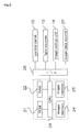
- Fig. 3 is a block diagram showing a principal structure of the control unit 20.
- This control unit 20 includes a ROM 21 for storing operating programs necessary for controlling the apparatus, a RAM 22 for temporarily storing data and the like during a control operation, a CPU 23 for performing logic operations, and a first and a second image memories 24 and 25.
- the control unit 20 is connected through an interface 26 to the control panel 15, light sources 13 and image pickup unit 14 noted above.
- the control unit 20 is connected also to an image data source 27 storing image data to be printed, such as a hard disk or an image processing device.
- the upper light-shielding plate 17 supported by the pair of posts 16 has a curved configuration extending in the fore and aft direction of the print tone measuring apparatus.
- the light-shielding plate 17 is installed in order to intercept light, such as light from indoor light sources, that would constitute a regular reflection from the table 12.
- the rear light-shielding plate 18 supported between the pair of posts 16 serves to intercept light coming from behind the print tone measuring apparatus.
- the auxiliary light source 19 attached to the rear light-shielding plate 18 serves to compensate for a lack of light on the table 12 caused by the upper light-shielding plate 17 and rear light-shielding plate 18.
- the auxiliary light source 19 is in the form of a fluorescent light or the like, which is turned off when reading an image of a print with the image pickup unit 14.
- FIG. 4 is a flow chart of the print tone measuring operation.
- the image of the reference paper is first read by using the print tone measuring apparatus (step S11). Specifically, the reference paper is placed on the table 12 and held thereon by suction. The reference paper is illuminated by the light sources 13, and the image of the reference paper is read by the image pickup unit 14. Data of the image of the reference paper is stored as first image data in the first image memory 24 of the control unit 20 (step S12).
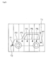
- Fig. 5 is an explanatory view showing the image of the reference paper displayed on the control panel 15.
- ink keys of the printing machine are divided into seven regions. Thus, seven regions corresponding to the ink keys are set to the image of the reference paper.
- control points are designated, which are key points for controlling the ink feeding rates (step S13). That is, based on the image of the reference paper displayed on the control panel 15, the operator designates control points P1-P7 (which may be collectively called "designated control points P") in the respective regions corresponding to the ink keys as shown in Fig. 5. These control points consist of representative points having colors that characterize a picture pattern on a print. The control points may be set automatically. In this specification, the control points set by the operator as described above are called designated control points. Information on the designated control points P1-P7 is stored in the first image memory 24 or RAM 22 of the control unit 20.
- a pair of first reference points T1 and T2 are designated for specifying image positions in the first image data (step S 14).
- the first reference points T1 and T2 preferably, are set to points on a diagonal line in the image.
- Information on these first reference points T1 and T2 is stored in the first image memory 24 or RAM 22 of the control unit 20.
- Step S3 and step S4 described above may be executed in reverse order.
- an image of an actual print is read (step S 15). Specifically, a print extracted by the operator from a discharge station of the printing machine during a printing operation is placed on the table 12, and held thereon by suction. This print is illuminated by the light sources 13, and the image of the print is read by the image pickup unit 14. Data of the image of the print is stored as second image data in the second image memory 25 of the control unit 20 (step S16).
- the image data of the print stored in the second image memory 24 is displayed on the control panel 15 as is the image data of the reference paper. Then, a pair of second reference points T3 and T4 are designated to correspond to the pair of first reference points T1 and T2 designated in the first image data (step S 17). Information on these second reference points T3 and T4 is stored in the second image memory 25 or RAM 22 of the control unit 20.
- control points on the image of the actual print corresponding to the positions of the above designated control points P1-P7 are calculated (step S18). Specifically, positions of the corresponding control points are determined by geometrical calculation from position data of the first reference points T1 and T2, second reference points T3 and T4 and designated control points P1-P7 determined previously. Seven such corresponding control points are set to the respective regions corresponding to the ink keys of the printing machine, as are the designated control points P1-P7 shown in Fig. 5. Information on these corresponding control points is stored in the second image memory 25 or RAM 22 of the control unit 20.
- This corresponding control point calculating step should provide the respective designated control points and corresponding control points having coordinates positions in agreement.
- a partial distortion of the image of the print could inhibit an accurate agreement between the coordinates of the designated control points on the reference paper and the coordinates of the corresponding control points on the print.
- the following steps are executed to achieve an accurate agreement between the coordinates of the designated control points on the reference paper and the coordinates of the corresponding control points on the print.
- image data adjacent each designated control point and image data adjacent the corresponding control point are extracted (step S19).
- Figs. 6A through 6C are explanatory views showing image data A adjacent a designated control point and image data B adjacent a corresponding control point.
- image data A adjacent the designated control point includes 169 pixels of each of R, G and B in an arrangement of 13 rows by 13 columns.
- image data B adjacent the corresponding control point includes 81 pixels of each of R, G and B in an arrangement of 9 rows by 9 columns.
- the position of the corresponding control point is corrected by comparing these image data A and B (step S20).
- image data A is larger in size than image data B in order to simplify an operating algorithm by causing the two image data to overlap each other constantly when determining differences between the pixels while shifting the image data pixel by pixel.
- the step of correcting the position of the corresponding control point is performed as follows.
- the image data B adjacent the corresponding control point is arranged relative to the image data A adjacent the designated control point with the respective upper and left ends placed in register.
- differences sums of R, G and B
- This cumulative addition is carried out, with the differences not taking negative values but taking absolute values.
- the image data B is shifted by one pixel to the right. Then, differences between all the pixels in the image data B and corresponding pixels in the image data A are added up and the resulting value is stored. This operation is repeated 25 times by moving the image data B rightward or downward by one pixel at a time. Consequently, as shown in Fig. 6C, the image data A and image data B assume an arrangement with the respective lower and right ends in register.
- a minimum value is determined among the 25 cumulative sums acquired by the above matching operation.
- the position of image data B adjacent the corresponding control point providing the minimum value is a position of an accurate corresponding control point.
- a necessary correction is made to the information on the corresponding control point previously stored in the second image memory 25 or RAM 22 of the control unit 20.
- the coordinates of the designated control point and the coordinates of the corresponding control point are thereby brought into accurate agreement even when a partial distortion occurs with the image of the print.
- the image data A adjacent each designated control point is extracted in 13 rows by 13 columns, and the image data B adjacent the corresponding control point is extracted in 9 rows by 9 columns.
- the position of the corresponding control point may be corrected even if the coordinates of the designated control point and the coordinates of the corresponding control point are displaced relative to each other by two pixels.
- the position of the corresponding control point may be corrected even if the coordinates of the designated control point and the coordinates of the corresponding control point are displaced relative to each other by three pixels.
- control data for controlling the ink feeding rates of the printing machine is calculated for the respective regions corresponding to the ink keys of the printing machine by using color data of the designated control points and color data of the corresponding control points (step S21).
- This control data is transmitted on-line or off-line through the interface 26 shown in Fig. 3 to the printing machine not shown.
- the above matching operation is described by way of example only, and a different pattern matching technique (calculation) may be used.
- step S22 whether a required number of prints have been made is determined.
- the operation in step S 15 to step S21 is repeated.
- the operator extracts a print, for image reading, from the discharge station of the printing machine upon completion of every 100 prints, for example.
- the operation is terminated.
- image data obtained by reading the image of the reference paper is used as the image data for reference.
- the image data supplied from the image data source 27 for platemaking purposes may be used as the reference image data.
- the described order of image reading from the reference paper and print may be reversed.
- the designated control points are set to the image of the reference paper, to correct the coordinates of the corresponding control points on the image of the actual print.
- designated control points may be set to the image of the actual print, to correct the coordinates of the corresponding control points on the image of the reference paper.
- Fig. 7 is a flow chart showing a print tone measuring method in a second embodiment.
- control data for controlling the ink feeding rates of the printing machine is calculated for the respective regions corresponding to the ink keys of the printing machine by using color data of the designated control points and color data of the corresponding control points.
- an image area usually is formed of halftone dots, and particularly where large halftone dots are used, a disagreement may occur between color information on a single pixel and color information on an image formed of a plurality of halftone dots.
- Noise of a CCD camera acting as an image pickup device, or dust or scratches on the print, may also hamper an accurate measurement based on color information on a single pixel.
- image data of a region including a designated control point among the image data adjacent the designated control point in the first image data is compared with a plurality of templates having different pixel arrangements. Pixels present in the same positions as the pixels arranged in a template are selected as relevant pixels in the first image data. Thereafter, data for controlling the ink feeding rates of the printing machine is calculated for the respective regions corresponding to the ink keys of the printing machine by comparing an average of colors of the relevant pixels in the first image data and an average of colors of relevant pixels in the second image data.
- a relevant pixel selecting step (step S41) is executed after steps S31 to S40 which are the same as steps S11 to S20 in the first embodiment.
- This relevant pixel selecting step is executed as follows.
- Fig. 8 is an explanatory view showing an image adjacent the designated control point P displayed on the control panel 15.
- a linear pattern I is shown to extend in the transverse direction.
- relevant pixels relating to each designated control point P are selected. Specifically, image data including the designated control point P among the image data adjacent the designated control point P extracted previously is compared with a plurality of templates having different pixel arrangements, and a template closest to the image of a region including the designated control point P is selected. Pixels present in the same positions as the pixels arranged in the selected template are selected as relevant pixels.
- Figs. 9A through 9H are schematic views showing eight templates having different pixel arrangements. These templates have regions arranged in five rows by five columns. In these figures, the regions having pixels are hatched.
- Mr [(A-F) 2 +(B-F) 2 +(C-F) 2 +(D-F) 2 +(E-F) 2 ] /5 where A, B, C, D and E are pixel values of the five pixels, and F is an average of the pixel values A, B, C, D and E.
- M (Mr+Mg+Mb) /3
- the template L providing a minimum distribution M among these distributions M is determined and selected as the closest to the pattern adjacent the designated control point P extracted previously.
- the template L shown in Fig. 9F is selected.
- the pixels arranged in the selected template L are selected as relevant pixels relating to the designated control point P.
- image data adjacent each control point is displayed on the control panel 15.
- relevant pixels relating to the corresponding control points are selected from the image data adjacent the corresponding control points.
- the center of selected template L shown in Fig. 9F may be placed to coincide with a corresponding control point.
- pixels arranged in the same positions as the pixels in the selected template L shown in Fig. 9F are selected as relevant pixels.
- control data for controlling the ink feeding rates of the printing machine is calculated for the respective regions corresponding to the ink keys of the printing machine by using color data of the designated control points and color data of the corresponding control points (step S42).
- an average of the colors of the relevant pixels relating to the designated control points P is determined as color of the designated control points.
- An average of the relevant pixels relating to the corresponding control points is determined as color of the corresponding control points. That is, the average of the colors of the relevant pixels relating to the designated control points P is used as data of the color of the designated control points, and the average of the relevant pixels relating to the corresponding control points is used as data of the corresponding control points.
- color may be measured accurately even where large halftone dots are used, noise occurs with a CCD camera, or dust or scratches is/are present on the print.
- Weighted averages may be used instead of an average of the colors of the relevant pixels relating to the designated control points P and an average of the relevant pixels relating to the corresponding control points.
- values of the control points may be regarded as high and values of surrounding areas regarded as low, or values may be weighted according to distances from the control points.
- control data is transmitted on-line or off-line through the interface 26 shown in Fig. 3 to the printing machine not shown.
- step S43 whether a required number of prints have been made is determined.
- the operation in step S35 to step S42 is repeated.
- the operator extracts a print, for image reading, from the discharge station of the printing machine upon completion of every 100 prints, for example.
- the operation is terminated.
- image data of a region including a designated control point among the image data adjacent the designated control point is compared with a plurality of templates having different pixel arrangements.
- a template closest to the image of the region including the designated control point is selected. Pixels present in the same positions as the pixels arranged in the selected template are selected as relevant pixels.
- pixels within a predetermined range of color differences with respect to the color of the designated control point may be selected as relevant pixels.
- step S41 shown in Fig. 7 may be executed to select pixels in the positions corresponding to the relevant pixels selected in step S4, as relevant pixels relating to the corresponding control point.
- image data obtained by reading the image of the reference paper is used as the image data for reference.
- the image data supplied from the image data source 27 for platemaking purposes may be used as the reference image data.
- the described order of image reading from the reference paper and print may be reversed.
- the designated control points are set to the image of the reference paper, to correct the coordinates of the corresponding control points in the image of the actual print.
- designated control points may be set to the image of the actual print, to correct the coordinates of the corresponding control points on the image of the reference paper.
Landscapes
- Engineering & Computer Science (AREA)
- Signal Processing (AREA)
- Multimedia (AREA)
- Health & Medical Sciences (AREA)
- Biomedical Technology (AREA)
- General Health & Medical Sciences (AREA)
- Quality & Reliability (AREA)
- General Physics & Mathematics (AREA)
- Theoretical Computer Science (AREA)
- Physics & Mathematics (AREA)
- Computer Vision & Pattern Recognition (AREA)
- Image Processing (AREA)
- Accessory Devices And Overall Control Thereof (AREA)
Applications Claiming Priority (4)
| Application Number | Priority Date | Filing Date | Title |
|---|---|---|---|
| JP2003166336 | 2003-06-11 | ||
| JP2003166335A JP2005003482A (ja) | 2003-06-11 | 2003-06-11 | 印刷物測定方法 |
| JP2003166335 | 2003-06-11 | ||
| JP2003166336A JP2005001212A (ja) | 2003-06-11 | 2003-06-11 | 印刷物測定方法 |
Publications (2)
| Publication Number | Publication Date |
|---|---|
| EP1486919A2 true EP1486919A2 (de) | 2004-12-15 |
| EP1486919A3 EP1486919A3 (de) | 2011-06-29 |
Family
ID=33302288
Family Applications (1)
| Application Number | Title | Priority Date | Filing Date |
|---|---|---|---|
| EP04013520A Withdrawn EP1486919A3 (de) | 2003-06-11 | 2004-06-08 | Drucktonmessverfahren |
Country Status (2)
| Country | Link |
|---|---|
| US (1) | US7418114B2 (de) |
| EP (1) | EP1486919A3 (de) |
Cited By (3)
| Publication number | Priority date | Publication date | Assignee | Title |
|---|---|---|---|---|
| EP1832421A1 (de) * | 2006-03-09 | 2007-09-12 | Dainippon Screen Mfg., Co., Ltd. | Verfahren zur Steuerung der Farbzufuhr und Gerät zur Bestimmung eines repräsentativen Punktes |
| JP2014008744A (ja) * | 2012-07-02 | 2014-01-20 | Mitsubishi Heavy Industries Printing & Packaging Machinery Ltd | 色調制御装置、印刷機、色調制御方法及びコンピュータプログラム |
| US20240022676A1 (en) * | 2022-07-15 | 2024-01-18 | Zhejiang University Of Technology | Method for acquiring color density characteristic curve in printing |
Families Citing this family (4)
| Publication number | Priority date | Publication date | Assignee | Title |
|---|---|---|---|---|
| JP2010234551A (ja) * | 2009-03-30 | 2010-10-21 | Fujifilm Corp | 画像形成装置 |
| JP6135059B2 (ja) * | 2011-08-16 | 2017-05-31 | 株式会社リコー | 画像検査装置、画像形成装置、画像検査装置の制御方法及び画像形成システム |
| US9031344B2 (en) * | 2012-04-18 | 2015-05-12 | Hewlett-Packard Industrial Printing Ltd. | Mobile device for measuring image quality |
| DE102015119819A1 (de) * | 2015-11-17 | 2017-05-18 | Uwe Sandig | Verfahren zur Messung der Farbdichte eines Druckerzeugnisses |
Family Cites Families (43)
| Publication number | Priority date | Publication date | Assignee | Title |
|---|---|---|---|---|
| US4752822A (en) * | 1983-03-08 | 1988-06-21 | Canon Kabushiki Kaisha | Color halftone image processing apparatus producing various screen angles and having an adaptive color image data conversion look-up table and a small-capacity masking memory |
| US4680805A (en) * | 1983-11-17 | 1987-07-14 | Texas Instruments Incorporated | Method and apparatus for recognition of discontinuous text |
| US4827526A (en) * | 1985-04-16 | 1989-05-02 | Fuji Photo Film Co., Ltd. | Image information detecting/processing method |
| DE68927970T2 (de) * | 1988-09-08 | 1997-10-09 | Canon Kk | Punktbilddatenausgabegerät |
| US5128711A (en) * | 1989-04-28 | 1992-07-07 | Fuji Photo Film Co., Ltd. | Apparatus for recording position information of principal image and method of detecting principal image |
| EP0400991B1 (de) * | 1989-05-31 | 1998-08-26 | Canon Kabushiki Kaisha | Farbbildverarbeitungsvorrichtung |
| CH679990A5 (de) * | 1989-06-08 | 1992-05-29 | Bobst Sa | |
| DE3924989A1 (de) * | 1989-07-28 | 1991-02-07 | Roland Man Druckmasch | Vorrichtung zur durchfuehrung einer umfassenden qualitaetskontrolle an druckbogen |
| JP3255409B2 (ja) * | 1990-11-29 | 2002-02-12 | キヤノン株式会社 | 画像形成装置 |
| DE4100170C2 (de) | 1991-01-05 | 1994-10-27 | Roland Man Druckmasch | Farbabstimmpult zur Qualitätskontrolle an Druckbogen |
| JP2899158B2 (ja) * | 1992-01-28 | 1999-06-02 | キヤノン株式会社 | インクジェット記録装置 |
| US5611023A (en) * | 1992-09-02 | 1997-03-11 | Ricoh Company, Ltd. | Apparatus and method for processing two-tone image data so as to smooth and magnify image |
| US5412577A (en) * | 1992-10-28 | 1995-05-02 | Quad/Tech International | Color registration system for a printing press |
| US5434956A (en) * | 1992-11-04 | 1995-07-18 | Hewlett-Packard Company | Method and apparatus for printing an image in a specified positional relationship with a preprinted registration mark |
| WO1995000337A1 (en) * | 1993-06-17 | 1995-01-05 | The Analytic Sciences Corporation | Automated system for print quality control |
| JP3488499B2 (ja) * | 1993-12-28 | 2004-01-19 | 株式会社東芝 | 印刷装置 |
| DE4401534C1 (de) * | 1994-01-20 | 1995-03-16 | Heidelberger Druckmasch Ag | Abmusterungseinrichtung zur visuellen Auflichtbeurteilung von flexiblen Vorlagen |
| US5708514A (en) * | 1994-08-31 | 1998-01-13 | Kabushiki Kaisha Toshiba | Error diffusion method in a multi-level image recording apparatus utilizing adjacent-pixel characteristics |
| US6081608A (en) * | 1995-02-09 | 2000-06-27 | Mitsubishi Jukogyo Kabushiki Kaisha | Printing quality examining method |
| JP3218910B2 (ja) | 1995-03-28 | 2001-10-15 | 凸版印刷株式会社 | 印刷物評価装置 |
| US5903712A (en) * | 1995-10-05 | 1999-05-11 | Goss Graphic Systems, Inc. | Ink separation device for printing press ink feed control |
| US5774225A (en) | 1996-03-27 | 1998-06-30 | Advanced Vision Technology, Ltd. | System and method for color measurement and control on-press during printing |
| US6408107B1 (en) * | 1996-07-10 | 2002-06-18 | Michael I. Miller | Rapid convolution based large deformation image matching via landmark and volume imagery |
| JPH1067099A (ja) | 1996-08-29 | 1998-03-10 | Toppan Printing Co Ltd | 印刷物検査装置 |
| US6382101B1 (en) | 1997-03-04 | 2002-05-07 | Heidelberg Harris, Inc. & Heidelberger Druckmaschinen | Remote ink fountain selection method and apparatus |
| US6024018A (en) | 1997-04-03 | 2000-02-15 | Intex Israel Technologies Corp., Ltd | On press color control system |
| JPH10305562A (ja) | 1997-05-02 | 1998-11-17 | Toppan Printing Co Ltd | 印刷物評価装置 |
| US6078701A (en) * | 1997-08-01 | 2000-06-20 | Sarnoff Corporation | Method and apparatus for performing local to global multiframe alignment to construct mosaic images |
| US5999636A (en) * | 1997-10-10 | 1999-12-07 | Printprobe Technology, Llc | Apparatus and process for inspecting print material |
| JP3980149B2 (ja) | 1998-02-13 | 2007-09-26 | 大日本印刷株式会社 | 複数カメラの位置ずれ補正方法及び装置 |
| US6275600B1 (en) * | 1998-03-09 | 2001-08-14 | I.Data International, Inc. | Measuring image characteristics of output from a digital printer |
| US6243501B1 (en) * | 1998-05-20 | 2001-06-05 | Canon Kabushiki Kaisha | Adaptive recognition of documents using layout attributes |
| JP2000067247A (ja) * | 1998-06-08 | 2000-03-03 | Toshiba Corp | 画像認識装置 |
| JP2000010090A (ja) | 1998-06-18 | 2000-01-14 | Casio Comput Co Ltd | 液晶表示装置 |
| US6351556B1 (en) * | 1998-11-20 | 2002-02-26 | Eastman Kodak Company | Method for automatically comparing content of images for classification into events |
| JP3998856B2 (ja) | 1999-05-19 | 2007-10-31 | 株式会社リコー | 画像形成装置 |
| DE19940879A1 (de) | 1999-08-27 | 2001-03-08 | Innomess Elektronik Gmbh | Verfahren und Vorrichtung zum automatisierten Vergleich von Druckbildern an Druckmaschinen |
| JP3781941B2 (ja) * | 2000-03-13 | 2006-06-07 | 大日本スクリーン製造株式会社 | 印刷装置 |
| JP2001353852A (ja) | 2000-04-10 | 2001-12-25 | Dainippon Screen Mfg Co Ltd | 印刷装置補助装置 |
| JP2001293847A (ja) | 2000-04-11 | 2001-10-23 | Mitsubishi Heavy Ind Ltd | 印刷物の色調測定方法及び装置 |
| JP2002192700A (ja) * | 2000-12-26 | 2002-07-10 | Dainippon Screen Mfg Co Ltd | 印刷制御装置および記録媒体 |
| US7202973B2 (en) | 2001-07-04 | 2007-04-10 | Dainippon Screen Mfg. Co., Ltd. | Patch measurement device |
| JP4254204B2 (ja) * | 2001-12-19 | 2009-04-15 | 富士ゼロックス株式会社 | 画像照合装置、画像形成装置及び画像照合プログラム |
-
2004
- 2004-06-04 US US10/860,155 patent/US7418114B2/en not_active Expired - Fee Related
- 2004-06-08 EP EP04013520A patent/EP1486919A3/de not_active Withdrawn
Cited By (5)
| Publication number | Priority date | Publication date | Assignee | Title |
|---|---|---|---|---|
| EP1832421A1 (de) * | 2006-03-09 | 2007-09-12 | Dainippon Screen Mfg., Co., Ltd. | Verfahren zur Steuerung der Farbzufuhr und Gerät zur Bestimmung eines repräsentativen Punktes |
| US7643176B2 (en) | 2006-03-09 | 2010-01-05 | Dainippon Screen Mfg. Co., Ltd. | Method and apparatus controlling printed color tone conditionally using a representative point or alternative representative point |
| JP2014008744A (ja) * | 2012-07-02 | 2014-01-20 | Mitsubishi Heavy Industries Printing & Packaging Machinery Ltd | 色調制御装置、印刷機、色調制御方法及びコンピュータプログラム |
| US20240022676A1 (en) * | 2022-07-15 | 2024-01-18 | Zhejiang University Of Technology | Method for acquiring color density characteristic curve in printing |
| US12075017B2 (en) * | 2022-07-15 | 2024-08-27 | Zhejiang University Of Technology | Method for acquiring color density characteristic curve in printing |
Also Published As
| Publication number | Publication date |
|---|---|
| EP1486919A3 (de) | 2011-06-29 |
| US20040252317A1 (en) | 2004-12-16 |
| US7418114B2 (en) | 2008-08-26 |
Similar Documents
| Publication | Publication Date | Title |
|---|---|---|
| US6275600B1 (en) | Measuring image characteristics of output from a digital printer | |
| JP2004108779A (ja) | 画像欠陥検査装置 | |
| US11267264B2 (en) | Method for automated alignment and register measurement using circular measuring marks | |
| US7800798B2 (en) | Print quality measuring method and print quality measuring apparatus | |
| US7283673B2 (en) | Image processing method and apparatus | |
| US7164496B2 (en) | Image correction apparatus | |
| US7418114B2 (en) | Print tone measuring method | |
| CN103245287A (zh) | 图像评估装置、图像评估方法以及非临时性存储介质 | |
| US20040212680A1 (en) | Device for determining a location-dependent intensity profile and color profile and/or sharpness profile of optical lens system | |
| US6976425B2 (en) | Ink feeding rate control method and an ink feeding rate control apparatus | |
| EP0834831A3 (de) | Verfahren und Gerät zur Bildinspektion in einem Druckplattenherstellungsverfahren | |
| US20050264835A1 (en) | Tone control method | |
| JPH10155091A (ja) | 画像記録装置 | |
| US7667867B2 (en) | Printing apparatus and correction data generating method | |
| JP3748209B2 (ja) | 網点面積率測定方法および網点面積率測定装置 | |
| JP2005001212A (ja) | 印刷物測定方法 | |
| JP3743397B2 (ja) | 画像処理方法、画像処理プログラム、および画像処理プログラムを記録した記録媒体 | |
| JP2025019643A (ja) | 画像処理装置、画像処理方法、及びプログラム | |
| JP2000004351A (ja) | 画像処理装置 | |
| JP2005003482A (ja) | 印刷物測定方法 | |
| CN120697460A (zh) | 印刷系统及程序产品 | |
| JPH11348241A (ja) | 印刷物検査方法及び装置 | |
| JP2001285594A (ja) | 画像読取装置、シェーディング異常検出方法、及び記憶媒体 | |
| JPH08323964A (ja) | レジスターマークの位置検出装置 | |
| JP3335729B2 (ja) | 絵柄の輪郭線抽出装置 |
Legal Events
| Date | Code | Title | Description |
|---|---|---|---|
| PUAI | Public reference made under article 153(3) epc to a published international application that has entered the european phase |
Free format text: ORIGINAL CODE: 0009012 |
|
| AK | Designated contracting states |
Kind code of ref document: A2 Designated state(s): AT BE BG CH CY CZ DE DK EE ES FI FR GB GR HU IE IT LI LU MC NL PL PT RO SE SI SK TR |
|
| AX | Request for extension of the european patent |
Extension state: AL HR LT LV MK |
|
| PUAL | Search report despatched |
Free format text: ORIGINAL CODE: 0009013 |
|
| AK | Designated contracting states |
Kind code of ref document: A3 Designated state(s): AT BE BG CH CY CZ DE DK EE ES FI FR GB GR HU IE IT LI LU MC NL PL PT RO SE SI SK TR |
|
| AX | Request for extension of the european patent |
Extension state: AL HR LT LV MK |
|
| RIC1 | Information provided on ipc code assigned before grant |
Ipc: H04N 1/00 20060101ALI20110525BHEP Ipc: H04N 1/23 20060101ALI20110525BHEP Ipc: G06T 7/00 20060101AFI20040916BHEP |
|
| AKY | No designation fees paid | ||
| REG | Reference to a national code |
Ref country code: DE Ref legal event code: R108 Effective date: 20120307 |
|
| STAA | Information on the status of an ep patent application or granted ep patent |
Free format text: STATUS: THE APPLICATION IS DEEMED TO BE WITHDRAWN |
|
| 18D | Application deemed to be withdrawn |
Effective date: 20111230 |