EP1486710A1 - Steuerventil und Flüssigkeitszuführungs-/Entleerungs- system - Google Patents
Steuerventil und Flüssigkeitszuführungs-/Entleerungs- system Download PDFInfo
- Publication number
- EP1486710A1 EP1486710A1 EP20040021881 EP04021881A EP1486710A1 EP 1486710 A1 EP1486710 A1 EP 1486710A1 EP 20040021881 EP20040021881 EP 20040021881 EP 04021881 A EP04021881 A EP 04021881A EP 1486710 A1 EP1486710 A1 EP 1486710A1
- Authority
- EP
- European Patent Office
- Prior art keywords
- valve
- coil
- fluid control
- fluid
- control valve
- Prior art date
- Legal status (The legal status is an assumption and is not a legal conclusion. Google has not performed a legal analysis and makes no representation as to the accuracy of the status listed.)
- Granted
Links
Images


Classifications
-
- F—MECHANICAL ENGINEERING; LIGHTING; HEATING; WEAPONS; BLASTING
- F16—ENGINEERING ELEMENTS AND UNITS; GENERAL MEASURES FOR PRODUCING AND MAINTAINING EFFECTIVE FUNCTIONING OF MACHINES OR INSTALLATIONS; THERMAL INSULATION IN GENERAL
- F16K—VALVES; TAPS; COCKS; ACTUATING-FLOATS; DEVICES FOR VENTING OR AERATING
- F16K31/00—Actuating devices; Operating means; Releasing devices
- F16K31/02—Actuating devices; Operating means; Releasing devices electric; magnetic
- F16K31/06—Actuating devices; Operating means; Releasing devices electric; magnetic using a magnet, e.g. diaphragm valves, cutting off by means of a liquid
- F16K31/08—Actuating devices; Operating means; Releasing devices electric; magnetic using a magnet, e.g. diaphragm valves, cutting off by means of a liquid using a permanent magnet
- F16K31/082—Actuating devices; Operating means; Releasing devices electric; magnetic using a magnet, e.g. diaphragm valves, cutting off by means of a liquid using a permanent magnet using a electromagnet and a permanent magnet
-
- F—MECHANICAL ENGINEERING; LIGHTING; HEATING; WEAPONS; BLASTING
- F16—ENGINEERING ELEMENTS AND UNITS; GENERAL MEASURES FOR PRODUCING AND MAINTAINING EFFECTIVE FUNCTIONING OF MACHINES OR INSTALLATIONS; THERMAL INSULATION IN GENERAL
- F16K—VALVES; TAPS; COCKS; ACTUATING-FLOATS; DEVICES FOR VENTING OR AERATING
- F16K31/00—Actuating devices; Operating means; Releasing devices
- F16K31/02—Actuating devices; Operating means; Releasing devices electric; magnetic
- F16K31/06—Actuating devices; Operating means; Releasing devices electric; magnetic using a magnet, e.g. diaphragm valves, cutting off by means of a liquid
- F16K31/0644—One-way valve
- F16K31/0655—Lift valves
-
- F—MECHANICAL ENGINEERING; LIGHTING; HEATING; WEAPONS; BLASTING
- F16—ENGINEERING ELEMENTS AND UNITS; GENERAL MEASURES FOR PRODUCING AND MAINTAINING EFFECTIVE FUNCTIONING OF MACHINES OR INSTALLATIONS; THERMAL INSULATION IN GENERAL
- F16K—VALVES; TAPS; COCKS; ACTUATING-FLOATS; DEVICES FOR VENTING OR AERATING
- F16K31/00—Actuating devices; Operating means; Releasing devices
- F16K31/02—Actuating devices; Operating means; Releasing devices electric; magnetic
- F16K31/06—Actuating devices; Operating means; Releasing devices electric; magnetic using a magnet, e.g. diaphragm valves, cutting off by means of a liquid
- F16K31/0644—One-way valve
- F16K31/0672—One-way valve the valve member being a diaphragm
-
- F—MECHANICAL ENGINEERING; LIGHTING; HEATING; WEAPONS; BLASTING
- F16—ENGINEERING ELEMENTS AND UNITS; GENERAL MEASURES FOR PRODUCING AND MAINTAINING EFFECTIVE FUNCTIONING OF MACHINES OR INSTALLATIONS; THERMAL INSULATION IN GENERAL
- F16K—VALVES; TAPS; COCKS; ACTUATING-FLOATS; DEVICES FOR VENTING OR AERATING
- F16K7/00—Diaphragm valves or cut-off apparatus, e.g. with a member deformed, but not moved bodily, to close the passage ; Pinch valves
- F16K7/12—Diaphragm valves or cut-off apparatus, e.g. with a member deformed, but not moved bodily, to close the passage ; Pinch valves with flat, dished, or bowl-shaped diaphragm
- F16K7/14—Diaphragm valves or cut-off apparatus, e.g. with a member deformed, but not moved bodily, to close the passage ; Pinch valves with flat, dished, or bowl-shaped diaphragm arranged to be deformed against a flat seat
-
- Y—GENERAL TAGGING OF NEW TECHNOLOGICAL DEVELOPMENTS; GENERAL TAGGING OF CROSS-SECTIONAL TECHNOLOGIES SPANNING OVER SEVERAL SECTIONS OF THE IPC; TECHNICAL SUBJECTS COVERED BY FORMER USPC CROSS-REFERENCE ART COLLECTIONS [XRACs] AND DIGESTS
- Y10—TECHNICAL SUBJECTS COVERED BY FORMER USPC
- Y10T—TECHNICAL SUBJECTS COVERED BY FORMER US CLASSIFICATION
- Y10T137/00—Fluid handling
- Y10T137/8158—With indicator, register, recorder, alarm or inspection means
- Y10T137/8225—Position or extent of motion indicator
- Y10T137/8242—Electrical
Definitions
- the present invention relates to a fluid control valve and fluid supply/exhaust system.
- the present invention refers to a fluid control valve, and a fluid supply/exhaust system, in which a member a which is made unitary with a rod shaped shaft which applies pressure to a valve holder is moved upwardly and downwardly by a coil using electromagnetic induction, and thereby, the portion between the valve seat and the valve holder is opened and closed.
- the fluid control valve and fluid supply/exhaust system of the present invention is chiefly used in semiconductor manufacturing apparatuses.
- valves which controlled fluids flowing through the valve body by means of opening and closing a portion between a valve seat and a valve holder using a drive unit had valve holders comprising a diaphragm and a diaphragm holder, and were of the following types.
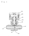
- Figure 4 is a schematic cross sectional view of an air pressure valve of a type in which the open and closed state of the valve is normally closed; the state is depicted in which the valve is closed.
- the opening and closing operation of the value is as given below.
- an actuator 402 pushes upward, and simultaneously therewith, a rod shaped valve rod 403 which is affixed to actuator 402 is pushed upward, so that the diaphragm 404, which is pushed against by valve rod 403, separates from valve seat 405, and the fluid flows from fluid input port 406 to fluid output port 407.
- the actuator 402 and the rod shaped valve rod 403 which is affixed to the actuator 402 are pushed downward as a result of the force of spring 408, and diaphragm 404 is pushed by valve rod 403 and diaphragm 404 comes into contact with valve 405, and the flow of the fluid from fluid input port 406 to fluid output port 407 is halted.
- FIG. 5 is a schematic cross sectional view of an electromagnetic valve in which the valve state is normally closed; the state is depicted in which the valve is closed.
- the opening and closing operation of the valve is as follows.
- the present invention has as an object thereof to provide a fluid control valve, and a fluid supply/discharge system, in which fluid can be stably controlled at a pressure of approximately 10 kg/cm 2 , the valves are high speed, having a response time of few milliseconds, and the miniaturization of the valve, and, since an instrumentation system is not required, the miniaturization of the fluid supply and exhaust system is possible, and in the case in which a system is constructed using a plurality of valves, there is little counter flow of the gas.
- the fluid control valve of the present invention is a fluid control valve in which a fluid moving through the valve body is controlled by the opening and closing of the portion between a valve seat and a valve holder using a drive unit, wherein this drive unit comprises a rod shaped shaft which applies pressure via a valve holder and a valve rod, and a member a which is fixed around the rod shaped shaft; the member a is made from a magnetic material, and has a space between it and the shaft, and a coil provided at a position parallel to the shaft moves the member a upwardly and downwardly by electromagnetic induction and makes use of a spring force to open and close a portion between the valve seat and the valve holder.
- this drive unit comprises a rod shaped shaft which applies pressure via a valve holder and a valve rod, and a member a which is fixed around the rod shaped shaft; the member a is made from a magnetic material, and has a space between it and the shaft, and a coil provided at a position parallel to the shaft moves the member a upward
- the present invention has the following functions.
- member a is constructed from a magnetic material, member a has a saturated magnetic flux density, so that by means of the electrical field generated by the coil, it is possible to pull the member a at a high rate of speed in the direction of the coil. Accordingly, the shaft which is made unitary with member a can also be moved upwardly and downwardly at a high rate of speed, so that it is possible to stably conduct the opening and closing of the portion between the valve seat and the valve holder at a high rate of speed. As a result, a fluid control valve is obtained which has a small response time.
- the valve holder comprises a diaphragm and a diaphragm holder, so that the structure of the parts and contact with gas is simple, and there is little dead space, and it is possible to obtain a fluid control valve having superior gas replacement characteristics.
- valve holder Furthermore, by disposing a bellows about the valve holder, it is possible to obtain a fluid control valve having superior durability in valve opening and closing.
- a magnetic material comprising an iron/cobalt system alloy having a saturation magnetic flux density of 2T (Tesla) or more, or by using, as member a2, a magnetic material comprising an iron/nickel system alloy having a saturation magnetic flux density of 2T (Tesla) or more, it is possible to greatly reduce the volume of member a, so that it is possible to achieve a miniaturization of the fluid control valve.
- the magnetic flux flowing out from one end of the coil at the side of member d is induced in the direction of the members b and c described above.
- the magnetic flux flowing out of one end of the coil at the side of member a is induced through members b and c described above into the other end of the coil; however, by providing member d, the convergence of magnetic flux at the other end of the coil is increased.
- the coil provided in parallel to the shaft from a plurality of coils disposed in series, then by means of the electromagnetic field generated by the coils described above, it is possible to increase the force with which member a is drawn in the direction of the coil at high speed, that is to say, to increase the drive force.
- members e comprising a magnetic material identical to that of member a, it is possible to make uniform the drive force described above, that is to say, the force with which the member a is pulled at high speed in a direction of the coil as a result of the electric field generated by the coil, and this is preferable.
- the magnetic material contains 5 percent by weight of vanadium, so that the workability of the material is improved. For this reason, it is possible to construct the fluid control valve at low cost. Furthermore, when the magnetic material contains 5 weight percent or less of vanadium, then it is possible to reduce the magnetic resistance while maintaining the high saturation magnetic flux density of the magnetic material. Accordingly, the permeability of the magnetic material (saturation magnetic flux density/magnetic resistance) increases, so that it is possible to more strongly induce the magnetic field flowing out of the coil.
- the soft landing control of the valve holder is possible. That is to say, the pushing force of the spring in the direction of the valve seat is reduced, so that as a result of reducing the valve closing speed, the shock effect of the valve holder with respect to the valve seat is ameliorated, and this essentially eliminates the occurrence of damage in the valve seat or valve holder.
- the structure by making the structure one in which the gap G positioned between the coil and member a, member b, and/or member c is filled in a freely chargeable and dischargeable manner with a magnetic fluid, it is possible to reduce the magnetic resistance of the portion of gap G corresponding to the valve stroke. As a result, it is possible to achieve a miniaturization of the drive unit which conducts the operation of pulling member a in the coil direction at high speed by means of the electrical field generated by the coil described above.
- the system comprises fluid control valves, a unit control apparatus which is provided with a power source, a control unit, and a plurality of drive units, a control computer which is provided in a remote central control point, and communication lines which connect the control computer with the unit control apparatus; by means of conducting operations of the fluid control valves by means of operational signals S from the control computer, a simplification of the communication lines is possible, and it is possible to rapidly and accurately control a plurality of fluid control valves simultaneously via the unit control apparatus, and a miniaturization and increase in control function of the fluid supply/exhaust system is possible.
- Figure 1 is a schematic cross sectional view showing an example of a fluid control valve in accordance with the present invention.
- reference 101 indicates a terminal
- reference 102 indicates a coil
- reference 103 indicates a case
- reference 104 indicates member a
- reference 105 indicates member b
- reference 106 indicates member c
- reference 107 indicates member d
- reference 108 indicates a shaft
- reference 109 indicates a valve rod
- reference 110 indicates a diaphragm holder
- reference 111 indicates a diaphragm
- reference 112 indicates a valve seat
- reference 113 indicates a fluid input port
- reference 114 indicates a fluid output port
- reference 115 indicates a spring
- reference 116 indicates a bonnet
- reference 117 indicates a screw for attaching bonnet 116 and case 103
- reference 118 indicates a screw for attaching shaft 108 and bonnet 118.
- diaphragm holder 110 and diaphragm 111 may be made unitary with the valve holder, or a bellows may be disposed about the valve holder.
- the drive unit which serves to open and close the portion between valve seat 112 and diaphragm 111 comprises a rod shaped shaft 108 for applying pressure to diaphragm 11 via diaphragm holder 110 and valve rod 109, and a member a (104) which is affixed about this rod shaped shaft 108.
- Member a (104) preferably comprises a magnetic material comprising an iron/cobalt system alloy or an iron/nickel system alloy having a saturation magnetic flux density of 2T (Tesla) or more.
- Coil 102 is positioned in parallel with shaft 108 and a space is present between coil 102 and shaft 108. Coil 102 moves member a (104) upwardly and downwardly by means of electromagnetic induction, and by means of employing the force of spring 115, it is possible to open and close the space between valve seat 112 and diaphragm 111.
- the drive force can be increased.
- the workability of the material is improved.
- the permeability of the magnetic material also increased, so that this is advantageous in that it is possible to more strongly induce the magnetic field flowing out from the coil.
- the exciting current supplied to the coil in such a manner as to be divided into a large initial drive current up to the opening of the valve and, after the opening of the valve, a small maintenance current to maintain the opened state of the valve, it is possible to suppress the power consumption in the drive unit conducting the operation by which member a is pulled at high speed in the direction of the coil as a result of the electric field generated by the coil, and it is possible to prevent damage to the coil resulting from heat.
- the soft landing control of the valve holder is made possible.
- the pushing force in the direction of the valve seat is reduced by the spring, so that the shock of the impact of the valve holder and valve seat is ameliorated as a result of a reduction in the valve opening speed, and it is possible to essentially eliminate the danger of damage to the valve seat or the valve holder.
- Figure 1 is a schematic cross sectional view of a normally closed type in which the valve is closed.
- Electricity is inputted from terminal 101 into coil 102, and thereby, coil 102 is electromagnetically induced, and coil 102 and member b (105) and member c (106) affixed to case 103 come into contact with member a1 or member a2 (104), and in accordance with this, the rod shaped shaft 108 which is affixed to member a1 or member a2 (104) is pushed upwards, so that the diaphragm 111 which is pushed by shaft 108 and the valve seat 112 are separated, and fluid flows from fluid input port 113 to fluid output 114.
- the fluid control valve of the present invention is a electrically controlled fluid control valve which conducts opening and closing operations at high speed and in a standard manner with respect to electrical signals, and which is, moreover, small and of high reliability, and furthermore, in order to increase the reliability, it is preferable that chromium oxide passivation treatment, which provides superior resistance to lack of water, corrosion resistance, and non catalytic properties to the surfaces of the parts in contact with gas, and fluoride passivation treatment, which provides superior corrosion resistance to fluorides, be conducted.
- the coil diameter: L which permitted the opening and closing operation of the valve was investigated.
- the coil diameter: L was altered by varying the number of turns of coil 102 within a range of 750 - 1500 T (0.3 m ⁇ , 12.6 ⁇ 20°C). At this time, the length of the coil in the direction of the shaft was fixed at a predetermined value.
- Figure 6 is a graph showing the relationship between the saturation magnetic flux density of the member a used to produce the fluid control valve and the coil diameter permitting the opening and closing operation of the valve.
- a member a1 comprising a magnetic material comprising an iron/cobalt system alloy
- a member a2 comprising a magnetic material comprising an iron/nickel system alloy
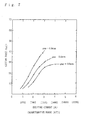
- the valve response times was measured while altering the saturation magnetic flux density of the two types of members.
- the member a1 and member a2 having differing saturation magnetic flux density materials were produced by altering the composition ratios of the various alloys.
- the coil diameter was set to 30 mm and the other points were identical to those of embodiment 1.
- Figure 2 is a graph showing the relationship between the saturation magnetic flux density of member a1 and member a2 and the response time. Furthermore, in Figure 2, the opening and closing state of the valve is shown in which a gas (nitrogen) is filled from the fluid input port at a pressure of 10 kg/cm 2 , and using the force of a spring, the diaphragm is pushed against the valve seat, and thereby, gas flow is stopped, and from this state, a current is passed through a coil at a fixed voltage, and by means of the resulting electromagnetic induction, member a1 or member a2 is drawn upward with a force stronger than that of the spring, and the gas filling the fluid input port is supplied to the fluid output port.
- a gas nitrogen
- Figures 8 and 9 show the operating characteristics during the opening operation and the closing operation of the fluid control valve shown in Figure 1, and during the opening of the valve, after approximately 0.007 seconds from the point at which operational signal S enters the ON state, the valve becomes fully open (a valve lift of approximately 0.3 mm). Furthermore, during the closing of the valve, after approximately 0.0031 sec from the point at which operational signal S is in the OFF state, the valve enters a fully closed state.
- the fluid control valve of the present invention it is possible to change the valve from fully closed to fully open at a high speed of approximately 0.01 second or less, and it is possible to change the valve from a fully opened to a fully closed state in approximately 0.005 seconds or less.
- the flow control valve of the present invention maintains approximately the same outer dimensions of the drive unit with respect to height, width, and depth, but achieves an approximately tenfold increase in the operating speed of the valve.
- valve structure in accordance with claim 1 or claim 2 of the present invention and by employing a member a1 and a member a2 having a saturation magnetic flux density of 2T (Teslas) or more, it is possibly to stably control the response time at a level of a few milliseconds of a gas at a pressure of 10 kg/cm 2 or less.
- Teslas saturation magnetic flux density
- a shaft (SUS316)108 of a nonmagnetic material formed so as to be unitary with the upper end of valve rod 109 is inserted, and by screwably engaging an affixing screw 118 which was affixed to the upper end of the plunger 119 with the screw part provided on the upper end of shaft 108, plunger 119 is supported and affixed on shaft 108 in such a manner as to be capable of upward and downward positional adjustment.
- a mechanism is provided for adjusting the gap G between the coil 102 and the member a 104.
- shaft 108 is urged in a downward direction by spring 115 with a force F of approximately 17 kgf, and by adjusting the amount of tightening of screw 118, the plunger 119 is moved in the upward or downward direction, and by means of this, the gap G between the member a 104 and the lower end surface of coil 102, the operating stroke G, is adjusted to, for example, 0.4 mm.
- Figure 7 is a graph showing the results of an investigation into the relationship between the exciting current and the suction force in the drive unit of Figure 1 when the initial gap G is altered.
- the plunger suction force of the drive unit was set to approximately 20 kgf (when the plunger operating stroke was set to approximately 0.4 mm); however, it is possible to appropriately regulate this by means of the force F of spring 115.
- valve rod 109 and shaft 108 were made unitary; however, these may also be formed so as to be separate.
- members b, c, and d are disposed in the fluid control valve shown in Figure 1.
- the magnetic material which was employed for members b, c, and d was the same as that of member a1.
- the dispositions of members b, c, and d were conducted in the combinations shown in Table 1.
- Table 1 the results of the measurement of the valve response time under conditions identical to those of embodiment 2 are shown. However, the response times shown in Table 1 represent values standardized by dividing response times obtained when using each combination of members by response times obtained in embodiment 1 employing only member a1 (that is to say, in which members b, c, and d were not used).
- Member combination Member Name Standardized Response Time a1 b c d 1 Present Absent Absent Absent 1 2 Present Present Absent Absent 0.97 3 Present Present Present Absent 0.94 4 Present Present Present Present 0.92
- members b, c, and d and the actuator body 120 had a cylindrical shape; however, these may also have the shape of a square tube.
- a fluid control valve will be discussed in which the coil 102, which is provided in parallel with the shaft, comprises a plurality of coils disposed in series.
- the fluid control valve of Figure 13 has a structure in which members b, c, and d were all disposed within the fluid control valve of Figure 1 (member combination 4 of embodiment 3), and all the other points were identical to those of embodiment 3.
- the settings were such that the outer diameter of actuator body 120 was 28 mm, while the inner diameter thereof was 23.6 mm ⁇ , and the height from the upper end surface of actuator body 120 to the central axis of valve body 121 was approximately 102 mm, the distance from the upper end surface of member d 107 to the lower end surface of member a 104 (when a current is not being conducted) was 50.4 mm, the number of turns of coil 102 was 940 T (at 0.3 m ⁇ , 12.6 ⁇ , at 20°C) and the outer diameter of plunger 119 was 6 mm, while the outer diameter of shaft 108 was 3 mm.
- Coil 102 is made into two coils 102a and b which are combined in series, and between these coils, a member e 124 comprising a magnetic material identical to that of the member a was provided.
- Figure 3 is a schematic diagram of a fluid supply and exhaust system comprising a gas source, a flow rate regulator, and a valve, together with devices into which fluid flows from this system.
- valve E is first closed, and next valve D is closed, and then valve C is opened, and the valves are switched in the order B, A (because the gas supplied from the gas source is at a higher pressure than the purged gas).
- valves in which the response speed is slow such as conventional air pressure valves, are employed, large irregularities are generated in the operational time of the various valves, so that phenomena such as the admixture of exhaust gases (when the valve C opens prior to the closing of valves E and D) or the admixture of fluid (a purge gas or a gas source gas) (when the opening and closing order of valves A and B is reversed), may occur.
- the type of gas source gas is changed, similar phenomena may occur.
- the fluid supply and exhaust system is structured in such a manner that the control of the opening and closing of a plurality (maximally approximately 20) of fluid control valves by means of an operational signal S from a control computer 24 provided at a central control point is conducted via a unit control apparatus 25 which is provided in the vicinity of the valves.
- the unit control apparatus 25 is provided with a power source 26, a control unit 27, drive units 28a-28n, and a communication port 29, and where necessary, valve opening detectors 31 may be provided at each fluid control valve.
- control computer 24 and the unit control apparatus 25 are connected via a dedicated protocol by means of a central communication system, and operational signal S is provided with respect to each fluid control valve via communication lines 30.
- a signal P indicating the operational state of each fluid control valve is inputted from the opening and closing detectors 31 of each fluid control valve into control unit 27, and this is sent back to control computer 24.
- control unit 27 of unit control apparatus 25 the adjustment control of exciting current I, and the soft landing control of diaphragm 111 during the closing of the valve, are conducted, where necessary.
- the drive units of each fluid control valve may be rapidly operated under a high suction force, so that a large exciting current I is required at the initiation of operations.
- gap G becomes smaller with the opening of the valve, in order to reduce the necessary exciting current I and prevent power consumption and the overheating of coil 102, it is desirable that the exciting current be steadily reduced after the opening of the valve.
- diaphragm 111 presses-toward the side of valve seat 112 at high speed in such a manner as to create a shock as a result of the elastic forces of spring 115 when exciting current I of coil 102 enters an OFF state, so that this leads to the production of impact noise, or to damage to diaphragm 111 or valve seat 112.
- control unit 27 sets the exciting current I to a maximum value during the startup of the valve opening operation (approximately 10 msec), and after the opening of the valve, reduces this to an elastic current I generating a suction force just sufficient to resist the elastic force of spring 115.
- the upper limit of the temperature is set to 30°C, then when the time during which the current is initially conducted (the state of the maximum exciting current) is 0.1 seconds, then it is not possible to set the repeated opening and closing periods of the fluid control valves at less than approximately 3.6 seconds, and if the opening and closing periods are set to 3.6 seconds or less, the increase in temperature will exceed 30°C.
- the minimum repeating opening and closing period when the upper limit of the temperature is set at 30°C can be reduced by approximately 1.5 times.
- control unit 27 causes the conduction of current for a short period of time after the passage of t msec.
- the compressive force in the downward direction from spring 115 is reduced, and since the valve closing speed is reduced, the shock of the impact of diaphragm 111 with respect to valve seat 112 can be prevented.
- the timing of the reamplification of exciting current I in Figure 11 may be by means of a method in which the time t from the point at which the operating signal S enters an OFF state to the initiation of the current (see Figure 11) is set in advance; however, in addition to this, a method in which a so-called trigger signal for re-sending the current is obtained by means of the operation of a switch mechanism or a potentiosensor provided at the fluid control valve side.
- the soft landing control a method may be employed in which a physical control method is employed in place of electrical control; for example, the lower inner space of actuator body 120 may be filled with a gel-form semifluid material, and a so-called dampening effect may be exercised thereby during the decent of valve rod 109 during the closing of the valve.
- the resin film comprises a compound other than tetrafluoroethylene resin such as, for example, trifluoroethylene resin, silicon resin, or the like.
- the thickness of this resin film was set to approximately 0.05 mm; however, this thickness may be appropriately set in accordance with the size of the valve stroke.
- Figure 12 shows another example of a fluid control rod in accordance with the present invention; this is a normally open type valve.
- the shaft 108 is constantly urged in an upward direction by spring 115, and diaphragm 111 is separated from valve seat 112, and fluid constantly flows from fluid input port 113, to fluid output port 114 (the state in which the valve is opened).
- Figure 14 shows another example of a fluid control valve in accordance with the present invention; a bellows is installed around the valve holder. The other points are completely identical to that of the structure of the fluid control valve shown in Figure 1.
- a fluid control valve and fluid supply and exhaust system are obtained in which it is possible to stably control a fluid at a pressure of approximately 10 kg/cm 2 , in which the valve response time is rapid, at a few milliseconds, in which the miniaturization of the valve is possible, and in which there is little gas counter flow when the construction involves a plurality of valves.
Priority Applications (1)
| Application Number | Priority Date | Filing Date | Title |
|---|---|---|---|
| EP20060005025 EP1666780B1 (de) | 1996-12-01 | 1997-12-01 | Steuerventil und Flüssigkeitszuführungs-/Entleerungs- system |
Applications Claiming Priority (7)
| Application Number | Priority Date | Filing Date | Title |
|---|---|---|---|
| JP33486696 | 1996-12-01 | ||
| JP33486696 | 1996-12-01 | ||
| JP32127696 | 1996-12-02 | ||
| JP32127696 | 1996-12-02 | ||
| JP32399596 | 1996-12-04 | ||
| JP32399596 | 1996-12-04 | ||
| EP97913482A EP0942214B1 (de) | 1996-12-01 | 1997-12-01 | Fluidreregelventil und fluid zu-und ablaufauslasssystem |
Related Parent Applications (1)
| Application Number | Title | Priority Date | Filing Date |
|---|---|---|---|
| EP97913482A Division EP0942214B1 (de) | 1996-12-01 | 1997-12-01 | Fluidreregelventil und fluid zu-und ablaufauslasssystem |
Related Child Applications (1)
| Application Number | Title | Priority Date | Filing Date |
|---|---|---|---|
| EP20060005025 Division EP1666780B1 (de) | 1996-12-01 | 1997-12-01 | Steuerventil und Flüssigkeitszuführungs-/Entleerungs- system |
Publications (2)
| Publication Number | Publication Date |
|---|---|
| EP1486710A1 true EP1486710A1 (de) | 2004-12-15 |
| EP1486710B1 EP1486710B1 (de) | 2007-02-14 |
Family
ID=27339839
Family Applications (4)
| Application Number | Title | Priority Date | Filing Date |
|---|---|---|---|
| EP20040021884 Expired - Lifetime EP1486711B1 (de) | 1996-12-01 | 1997-12-01 | Steuerventil und Flüssigkeitszuführungs-/Entleerungs- system |
| EP20040021881 Expired - Lifetime EP1486710B1 (de) | 1996-12-01 | 1997-12-01 | Steuerventil und Flüssigkeitszuführungs-/Entleerungs- system |
| EP20060005025 Expired - Lifetime EP1666780B1 (de) | 1996-12-01 | 1997-12-01 | Steuerventil und Flüssigkeitszuführungs-/Entleerungs- system |
| EP97913482A Expired - Lifetime EP0942214B1 (de) | 1996-12-01 | 1997-12-01 | Fluidreregelventil und fluid zu-und ablaufauslasssystem |
Family Applications Before (1)
| Application Number | Title | Priority Date | Filing Date |
|---|---|---|---|
| EP20040021884 Expired - Lifetime EP1486711B1 (de) | 1996-12-01 | 1997-12-01 | Steuerventil und Flüssigkeitszuführungs-/Entleerungs- system |
Family Applications After (2)
| Application Number | Title | Priority Date | Filing Date |
|---|---|---|---|
| EP20060005025 Expired - Lifetime EP1666780B1 (de) | 1996-12-01 | 1997-12-01 | Steuerventil und Flüssigkeitszuführungs-/Entleerungs- system |
| EP97913482A Expired - Lifetime EP0942214B1 (de) | 1996-12-01 | 1997-12-01 | Fluidreregelventil und fluid zu-und ablaufauslasssystem |
Country Status (9)
| Country | Link |
|---|---|
| US (2) | US6193212B1 (de) |
| EP (4) | EP1486711B1 (de) |
| JP (1) | JP3845454B2 (de) |
| KR (1) | KR100495897B1 (de) |
| AT (4) | ATE292766T1 (de) |
| DE (4) | DE69737841T2 (de) |
| IL (1) | IL129792A (de) |
| TW (2) | TW506498U (de) |
| WO (1) | WO1998025062A1 (de) |
Cited By (1)
| Publication number | Priority date | Publication date | Assignee | Title |
|---|---|---|---|---|
| WO2008052954A1 (de) * | 2006-11-02 | 2008-05-08 | Continental Teves Ag & Co. Ohg | Proportionalregelventil |
Families Citing this family (54)
| Publication number | Priority date | Publication date | Assignee | Title |
|---|---|---|---|---|
| US6537505B1 (en) * | 1998-02-20 | 2003-03-25 | Bio Dot, Inc. | Reagent dispensing valve |
| DE19922423A1 (de) * | 1999-05-14 | 2000-11-30 | Siemens Ag | Elektromechanischer Stellantrieb |
| US6293516B1 (en) | 1999-10-21 | 2001-09-25 | Arichell Technologies, Inc. | Reduced-energy-consumption actuator |
| US6739573B1 (en) * | 1999-10-28 | 2004-05-25 | Siemens Canada Limited | Canister purge valve noise attenuation |
| DE69931787T2 (de) * | 1999-11-11 | 2007-05-24 | The Provost, Fellows And Scholars Of The College Of The Holy And Undivided Trinity Of Queen Elizabeth Near Dublin | Vorrichtung und Verfahren zur Verabreichung von Tropfen |
| US20070241298A1 (en) | 2000-02-29 | 2007-10-18 | Kay Herbert | Electromagnetic apparatus and method for controlling fluid flow |
| US6948697B2 (en) | 2000-02-29 | 2005-09-27 | Arichell Technologies, Inc. | Apparatus and method for controlling fluid flow |
| US6305662B1 (en) | 2000-02-29 | 2001-10-23 | Arichell Technologies, Inc. | Reduced-energy-consumption actuator |
| DE10062487C1 (de) * | 2000-12-14 | 2002-03-07 | Gruner Ag | Elektromagnetventil |
| US6669909B2 (en) * | 2001-03-26 | 2003-12-30 | Allegro Technologies Limited | Liquid droplet dispensing |
| DE10124847A1 (de) * | 2001-05-22 | 2002-11-28 | Abb Patent Gmbh | Verfahren zum Betrieb eines Stellantriebs |
| JP2003156169A (ja) * | 2001-09-04 | 2003-05-30 | Denso Corp | 電磁式流体制御装置 |
| US7222636B2 (en) * | 2002-08-20 | 2007-05-29 | Applied Materials, Inc. | Electronically actuated valve |
| US6749136B1 (en) * | 2002-11-26 | 2004-06-15 | Orbit Irrigation Products, Inc. | Enhanced sprinkler valving apparatus and method |
| US6907897B2 (en) | 2003-06-26 | 2005-06-21 | Planar Systems, Inc. | Diaphragm valve for high-temperature precursor supply in atomic layer deposition |
| US6941963B2 (en) * | 2003-06-26 | 2005-09-13 | Planar Systems, Inc. | High-speed diaphragm valve for atomic layer deposition |
| US7021330B2 (en) | 2003-06-26 | 2006-04-04 | Planar Systems, Inc. | Diaphragm valve with reliability enhancements for atomic layer deposition |
| JP4383933B2 (ja) * | 2004-03-15 | 2009-12-16 | 三菱電機株式会社 | 電動制御弁の出力軸接続構造の製造方法 |
| US7628860B2 (en) * | 2004-04-12 | 2009-12-08 | Mks Instruments, Inc. | Pulsed mass flow delivery system and method |
| JP2005299811A (ja) * | 2004-04-13 | 2005-10-27 | Tgk Co Ltd | 流体制御弁 |
| DE102005008010B4 (de) | 2005-02-22 | 2022-01-27 | Zf Friedrichshafen Ag | Verfahren zur Erhöhung der Spontaneität bei Schaltungen eines Automatgetriebes oder eines automatisierten Schaltgetriebes |
| JP4743763B2 (ja) * | 2006-01-18 | 2011-08-10 | 株式会社フジキン | 圧電素子駆動式金属ダイヤフラム型制御弁 |
| KR100927896B1 (ko) * | 2007-09-19 | 2009-11-25 | 주식회사 세 바 | 유체제어밸브 |
| JP4644242B2 (ja) * | 2007-12-10 | 2011-03-02 | 忠弘 大見 | 真空排気系用バルブの使用方法 |
| US8430378B2 (en) * | 2008-05-30 | 2013-04-30 | South Bend Controls Holdings Llc | High flow proportional valve |
| EP2159462B1 (de) * | 2008-09-01 | 2015-01-14 | Siemens Aktiengesellschaft | Kupplungselement zum Anschluss eines Aktuators an ein Ventil |
| US20100212763A1 (en) * | 2009-02-24 | 2010-08-26 | Means Stephen R | Well gauging system and method |
| KR100924265B1 (ko) | 2009-05-28 | 2009-10-30 | 신우공업 주식회사 | 전자제어밸브 |
| CN101839362B (zh) * | 2010-06-18 | 2011-06-15 | 欧好光电控制技术(上海)有限公司 | 常闭式半自动燃气紧急切断电磁阀 |
| EP2453122B1 (de) | 2010-11-12 | 2016-09-07 | Hitachi, Ltd. | Verfahren und Steuergerät zur Steuerung einer Hochdruckkraftstoffförderpumpe zur Speisung von Kraftstoff unter Druck in einen Verbrennungsmotor |
| DE102010061271A1 (de) * | 2010-12-15 | 2012-06-21 | Contitech Schlauch Gmbh | Beheizbare Anschlussvorrichtung für medienführende, elektrisch beheizbare Schläuche |
| US9353886B2 (en) | 2011-12-29 | 2016-05-31 | Koge Micro Tech Co., Ltd. | Solenoid valve having air tap structure |
| TWI451029B (zh) * | 2011-12-29 | 2014-09-01 | Koge Electronics Co Ltd | 具氣嘴構造之電磁閥 |
| RU2516057C2 (ru) * | 2012-06-14 | 2014-05-20 | Рауф Рахимович Сафаров | Клапан перепускной дискретного действия с магнитной фиксацей, разгрузкой и контролем положения |
| CN102777653B (zh) * | 2012-07-25 | 2013-11-06 | 欧好光电控制技术(上海)有限公司 | 工业级含储能关阀模块的电磁式燃气紧急切断阀 |
| US9454158B2 (en) | 2013-03-15 | 2016-09-27 | Bhushan Somani | Real time diagnostics for flow controller systems and methods |
| CN103672147A (zh) * | 2013-11-28 | 2014-03-26 | 武汉工程大学 | 流体稳压调节阀 |
| US9911561B2 (en) | 2015-11-13 | 2018-03-06 | Target Rock Division Of Curtiss-Wright Flow Control Corporation | Solenoid current control with fault detection, override, and shutdown features |
| NL2016009B1 (nl) * | 2015-12-22 | 2017-07-03 | Eskens Solutions B V | Werkwijze voor het doseren van een kleurpasta. |
| RU2617651C1 (ru) * | 2016-06-01 | 2017-04-25 | Иван Николаевич Селиванов | Клапан магниторегулируемый |
| DE102016112115A1 (de) * | 2016-07-01 | 2018-01-04 | Bürkert Werke GmbH | Ventillinearantrieb sowie Ventil |
| US10993546B2 (en) | 2016-10-28 | 2021-05-04 | Sleep Number Corporation | Noise reducing plunger |
| US10983537B2 (en) | 2017-02-27 | 2021-04-20 | Flow Devices And Systems Inc. | Systems and methods for flow sensor back pressure adjustment for mass flow controller |
| JP6153684B1 (ja) * | 2017-04-03 | 2017-06-28 | 伸和コントロールズ株式会社 | 酸素、水素及び水に対する耐久性を有する電磁弁 |
| GB2564703A (en) * | 2017-07-21 | 2019-01-23 | Weir Group Ip Ltd | Valve |
| US11460869B2 (en) | 2017-07-31 | 2022-10-04 | Fujikin Incorporated | Fluid control system and flow rate measurement method |
| CN107676495B (zh) * | 2017-09-21 | 2019-03-26 | 安徽荣达阀门有限公司 | 一种检测水质的阀门系统 |
| WO2019065117A1 (ja) * | 2017-09-29 | 2019-04-04 | 株式会社フジキン | 手動バルブ装置および流体制御装置 |
| WO2019079426A1 (en) | 2017-10-17 | 2019-04-25 | Automotive Technologies International, Inc. | HIGH SPEED VALVE |
| US11486313B2 (en) * | 2019-06-14 | 2022-11-01 | Hamilton Sundstrand Corporation | Linear electric air valve |
| CN110701312A (zh) * | 2019-10-15 | 2020-01-17 | 中冶华天工程技术有限公司 | 一种高压干油气控阀 |
| CN113447261A (zh) * | 2021-07-16 | 2021-09-28 | 上海廷本流体控制有限公司 | 用于安全阀的检测系统及检测方法 |
| US11832728B2 (en) | 2021-08-24 | 2023-12-05 | Sleep Number Corporation | Controlling vibration transmission within inflation assemblies |
| KR102585781B1 (ko) | 2021-09-08 | 2023-10-05 | 주식회사 현대케피코 | 차량의 연료탱크 차단밸브 |
Citations (8)
| Publication number | Priority date | Publication date | Assignee | Title |
|---|---|---|---|---|
| US3174716A (en) * | 1962-10-15 | 1965-03-23 | Salter Jack Nelson | Magnetostrictive multiplier device |
| EP0289337A2 (de) * | 1987-04-30 | 1988-11-02 | AlliedSignal Inc. | Magnetventil |
| US4813647A (en) * | 1986-11-24 | 1989-03-21 | Nippondenso Co., Ltd. | Electromagnetic actuator for controlling fluid flow |
| US5094429A (en) * | 1990-03-09 | 1992-03-10 | Siemens Aktiengesellschaft | Valve having piezoelecrtric drive |
| DE4310984A1 (de) * | 1993-04-03 | 1994-10-06 | Rexroth Mannesmann Gmbh | Elektromagnetisch betätigbares hydraulisches Schaltventil |
| EP0701053A2 (de) * | 1994-09-09 | 1996-03-13 | General Motors Corporation | Stellantrieb für ein Abgasrückführungsventil |
| US5501425A (en) * | 1994-09-21 | 1996-03-26 | Marotta Scientific Controls, Inc. | Magnetostrictively actuated valve |
| EP0709606A2 (de) * | 1994-10-25 | 1996-05-01 | MANNESMANN Aktiengesellschaft | Elektromagnetisch gesteuertes Wegesitzventil |
Family Cites Families (26)
| Publication number | Priority date | Publication date | Assignee | Title |
|---|---|---|---|---|
| US3633869A (en) * | 1970-07-31 | 1972-01-11 | Danfoss As | Solenoid valve with adjustable stroke |
| US4165762A (en) * | 1978-02-21 | 1979-08-28 | International Telephone And Telegraph Corporation | Latching valve |
| DE2862229D1 (en) * | 1978-07-06 | 1983-05-19 | Burkert Gmbh | Electronically controlled magnetic valve |
| JPS59133884A (ja) | 1983-01-20 | 1984-08-01 | Matsushita Electric Ind Co Ltd | 電磁弁 |
| DE3437487A1 (de) * | 1984-10-12 | 1986-04-17 | H. Kuhnke Gmbh Kg, 2427 Malente | Bistabiles magnetventil |
| US4757943A (en) * | 1984-12-24 | 1988-07-19 | Naiad Company Usa | Method and apparatus for controlling the temperature of a liquid |
| JPS6220980A (ja) | 1985-07-18 | 1987-01-29 | Diesel Kiki Co Ltd | 電磁弁 |
| JPS62188872A (ja) | 1986-02-13 | 1987-08-18 | Tokyo Keiki Co Ltd | 流体制御弁の通信制御システム |
| JPS63318380A (ja) | 1987-06-23 | 1988-12-27 | Hitachi Ltd | 電磁弁の磁気回路部材及びその製造方法 |
| US4829947A (en) * | 1987-08-12 | 1989-05-16 | General Motors Corporation | Variable lift operation of bistable electromechanical poppet valve actuator |
| JPH01241104A (ja) | 1988-03-22 | 1989-09-26 | Tokin Corp | 吸着電磁石 |
| JP2635663B2 (ja) | 1988-03-23 | 1997-07-30 | 日立金属株式会社 | プリンタ用ヘッド |
| JPH0231088A (ja) | 1988-07-20 | 1990-02-01 | Matsushita Electric Ind Co Ltd | 電磁弁 |
| JPH0361776A (ja) | 1989-07-26 | 1991-03-18 | Takasago Denki Kogyo Kk | 直流ソレノイドバルブ |
| US4988907A (en) * | 1990-01-30 | 1991-01-29 | Lucas Ledex Inc. | Independent redundant force motor |
| IT220662Z2 (it) | 1990-10-31 | 1993-10-08 | Elasis Sistema Ricerca Fita Nel Mezzogiorno Soc.Consortile P.A. | Perfezionamenti alla valvola pilota e alla relativa ancora di comando odi un iniettore elettromagnetico per sistemi di iniezione del combustibile di motori a combustione interna |
| DE4036491C2 (de) * | 1990-11-16 | 1994-01-27 | Danfoss As | Magnetventil |
| JP2611539B2 (ja) | 1990-11-19 | 1997-05-21 | 三菱マテリアル株式会社 | 微小力によって作動する弁 |
| DE69219614T3 (de) * | 1991-09-10 | 2001-05-03 | Smc Kk | Flüssigkeitsdruckvorrichtung |
| US5458048A (en) * | 1992-08-19 | 1995-10-17 | Festo Kg | Electro-pneumatic control device |
| JPH06207684A (ja) | 1992-08-28 | 1994-07-26 | Taiheiyo Kogyo Kk | 無音電磁弁 |
| US5548263A (en) * | 1992-10-05 | 1996-08-20 | Aura Systems, Inc. | Electromagnetically actuated valve |
| US5333643A (en) * | 1993-03-24 | 1994-08-02 | South Bend Controls, Inc. | Solenoid valve |
| JP3437300B2 (ja) * | 1994-12-02 | 2003-08-18 | Smc株式会社 | 電磁弁制御装置 |
| DE19631909A1 (de) * | 1995-08-08 | 1997-02-13 | Fev Motorentech Gmbh & Co Kg | Verfahren zur Justierung der Ruhelage des Ankers an einem elektromganetischen Aktuator |
| JP3552849B2 (ja) * | 1996-07-12 | 2004-08-11 | 株式会社東芝 | 制御棒駆動機構の水圧駆動システムおよびその運用方法 |
-
1997
- 1997-11-28 TW TW91206683U patent/TW506498U/zh unknown
- 1997-11-28 TW TW89222640U patent/TW479773U/zh not_active IP Right Cessation
- 1997-12-01 WO PCT/JP1997/004377 patent/WO1998025062A1/ja active IP Right Grant
- 1997-12-01 US US09/308,922 patent/US6193212B1/en not_active Expired - Lifetime
- 1997-12-01 DE DE1997637841 patent/DE69737841T2/de not_active Expired - Lifetime
- 1997-12-01 EP EP20040021884 patent/EP1486711B1/de not_active Expired - Lifetime
- 1997-12-01 KR KR10-1999-7004536A patent/KR100495897B1/ko not_active IP Right Cessation
- 1997-12-01 AT AT97913482T patent/ATE292766T1/de not_active IP Right Cessation
- 1997-12-01 AT AT04021884T patent/ATE318384T1/de not_active IP Right Cessation
- 1997-12-01 AT AT04021881T patent/ATE354048T1/de not_active IP Right Cessation
- 1997-12-01 EP EP20040021881 patent/EP1486710B1/de not_active Expired - Lifetime
- 1997-12-01 AT AT06005025T patent/ATE365292T1/de not_active IP Right Cessation
- 1997-12-01 DE DE1997637377 patent/DE69737377T2/de not_active Expired - Lifetime
- 1997-12-01 EP EP20060005025 patent/EP1666780B1/de not_active Expired - Lifetime
- 1997-12-01 EP EP97913482A patent/EP0942214B1/de not_active Expired - Lifetime
- 1997-12-01 JP JP52544198A patent/JP3845454B2/ja not_active Expired - Fee Related
- 1997-12-01 IL IL12979297A patent/IL129792A/en not_active IP Right Cessation
- 1997-12-01 DE DE1997635280 patent/DE69735280T2/de not_active Expired - Lifetime
- 1997-12-01 DE DE1997632976 patent/DE69732976T2/de not_active Expired - Lifetime
-
2000
- 2000-07-27 US US09/627,784 patent/US6394415B1/en not_active Expired - Lifetime
Patent Citations (8)
| Publication number | Priority date | Publication date | Assignee | Title |
|---|---|---|---|---|
| US3174716A (en) * | 1962-10-15 | 1965-03-23 | Salter Jack Nelson | Magnetostrictive multiplier device |
| US4813647A (en) * | 1986-11-24 | 1989-03-21 | Nippondenso Co., Ltd. | Electromagnetic actuator for controlling fluid flow |
| EP0289337A2 (de) * | 1987-04-30 | 1988-11-02 | AlliedSignal Inc. | Magnetventil |
| US5094429A (en) * | 1990-03-09 | 1992-03-10 | Siemens Aktiengesellschaft | Valve having piezoelecrtric drive |
| DE4310984A1 (de) * | 1993-04-03 | 1994-10-06 | Rexroth Mannesmann Gmbh | Elektromagnetisch betätigbares hydraulisches Schaltventil |
| EP0701053A2 (de) * | 1994-09-09 | 1996-03-13 | General Motors Corporation | Stellantrieb für ein Abgasrückführungsventil |
| US5501425A (en) * | 1994-09-21 | 1996-03-26 | Marotta Scientific Controls, Inc. | Magnetostrictively actuated valve |
| EP0709606A2 (de) * | 1994-10-25 | 1996-05-01 | MANNESMANN Aktiengesellschaft | Elektromagnetisch gesteuertes Wegesitzventil |
Cited By (2)
| Publication number | Priority date | Publication date | Assignee | Title |
|---|---|---|---|---|
| WO2008052954A1 (de) * | 2006-11-02 | 2008-05-08 | Continental Teves Ag & Co. Ohg | Proportionalregelventil |
| US8151952B2 (en) | 2006-11-02 | 2012-04-10 | Continental Teves Ag & Co. Ohg | Proportional control valve |
Also Published As
| Publication number | Publication date |
|---|---|
| EP0942214A1 (de) | 1999-09-15 |
| EP1486711A2 (de) | 2004-12-15 |
| DE69737841T2 (de) | 2008-02-07 |
| DE69737841D1 (de) | 2007-08-02 |
| DE69732976T2 (de) | 2006-02-16 |
| KR20000057204A (ko) | 2000-09-15 |
| DE69737377D1 (de) | 2007-03-29 |
| ATE365292T1 (de) | 2007-07-15 |
| DE69735280T2 (de) | 2006-10-12 |
| US6193212B1 (en) | 2001-02-27 |
| EP1486711B1 (de) | 2006-02-22 |
| DE69732976D1 (de) | 2005-05-12 |
| EP1486710B1 (de) | 2007-02-14 |
| IL129792A0 (en) | 2000-02-29 |
| JP3845454B2 (ja) | 2006-11-15 |
| US6394415B1 (en) | 2002-05-28 |
| ATE292766T1 (de) | 2005-04-15 |
| DE69735280D1 (de) | 2006-04-27 |
| IL129792A (en) | 2002-12-01 |
| EP0942214A4 (de) | 2002-07-31 |
| KR100495897B1 (ko) | 2005-06-17 |
| TW506498U (en) | 2002-10-11 |
| EP1486711A3 (de) | 2004-12-22 |
| TW479773U (en) | 2002-03-11 |
| EP1666780A1 (de) | 2006-06-07 |
| EP0942214B1 (de) | 2005-04-06 |
| ATE318384T1 (de) | 2006-03-15 |
| ATE354048T1 (de) | 2007-03-15 |
| WO1998025062A1 (fr) | 1998-06-11 |
| DE69737377T2 (de) | 2007-11-29 |
| EP1666780B1 (de) | 2007-06-20 |
Similar Documents
| Publication | Publication Date | Title |
|---|---|---|
| EP0942214B1 (de) | Fluidreregelventil und fluid zu-und ablaufauslasssystem | |
| US5785298A (en) | Proportional solenoid-controlled fluid valve assembly | |
| TW381205B (en) | Gas supplying device with a pressure flow controller | |
| EP0107445B1 (de) | Elektromagnetisches Ventil | |
| JP2509179B2 (ja) | 燃料の計量に関する改良 | |
| US8757588B2 (en) | Valve with an electromagnetic drive | |
| US5251659A (en) | High speed miniature solenoid | |
| US20120298896A1 (en) | Pilot solenoid valve | |
| WO2005057064A1 (ja) | 電磁弁 | |
| WO2006137404A1 (ja) | 流量制御弁 | |
| JPH0784650A (ja) | マスフローコントローラ、その運転方法及び電磁弁 | |
| US3926405A (en) | Solenoid operated proportional valve | |
| US20050145812A1 (en) | Solenoid valve and poppet assembly | |
| JP3764598B2 (ja) | ソレノイド駆動式金属ダイヤフラム型開閉制御弁 | |
| US20140001385A1 (en) | Adjustable Solenoid-Operated Directional Valve | |
| JPH0384285A (ja) | 閉止機能付き流量調製弁 | |
| CN110131442A (zh) | 一种三通控制阀结构 | |
| US20200224772A1 (en) | Solenoid Valve with a Pneumatic Cylinder | |
| JP4262036B2 (ja) | 定流量膨張弁 | |
| JP2021196001A (ja) | 流量調整弁 | |
| RU2752959C1 (ru) | Клапан электромагнитный нормально закрытый | |
| JPS6188001A (ja) | 電気空気式コンバータ用のボイスコイルアセンブリ | |
| JP2655967B2 (ja) | 電磁弁 | |
| SU1767265A1 (ru) | Электромагнитный клапан | |
| JPH11513536A (ja) | 可動プレートと電磁リニアアクチュエータによって制御されるバルブ液体レギュレータとを備えた電磁リニアアクチュエータ |
Legal Events
| Date | Code | Title | Description |
|---|---|---|---|
| PUAI | Public reference made under article 153(3) epc to a published international application that has entered the european phase |
Free format text: ORIGINAL CODE: 0009012 |
|
| 17P | Request for examination filed |
Effective date: 20040915 |
|
| AC | Divisional application: reference to earlier application |
Ref document number: 0942214 Country of ref document: EP Kind code of ref document: P |
|
| AK | Designated contracting states |
Kind code of ref document: A1 Designated state(s): AT DE FR GB IT |
|
| 17Q | First examination report despatched |
Effective date: 20050620 |
|
| AKX | Designation fees paid |
Designated state(s): AT DE FR GB IT |
|
| GRAP | Despatch of communication of intention to grant a patent |
Free format text: ORIGINAL CODE: EPIDOSNIGR1 |
|
| GRAS | Grant fee paid |
Free format text: ORIGINAL CODE: EPIDOSNIGR3 |
|
| GRAA | (expected) grant |
Free format text: ORIGINAL CODE: 0009210 |
|
| AC | Divisional application: reference to earlier application |
Ref document number: 0942214 Country of ref document: EP Kind code of ref document: P |
|
| AK | Designated contracting states |
Kind code of ref document: B1 Designated state(s): AT DE FR GB IT |
|
| REG | Reference to a national code |
Ref country code: GB Ref legal event code: FG4D |
|
| REF | Corresponds to: |
Ref document number: 69737377 Country of ref document: DE Date of ref document: 20070329 Kind code of ref document: P |
|
| ET | Fr: translation filed | ||
| PLBE | No opposition filed within time limit |
Free format text: ORIGINAL CODE: 0009261 |
|
| STAA | Information on the status of an ep patent application or granted ep patent |
Free format text: STATUS: NO OPPOSITION FILED WITHIN TIME LIMIT |
|
| 26N | No opposition filed |
Effective date: 20071115 |
|
| PGFP | Annual fee paid to national office [announced via postgrant information from national office to epo] |
Ref country code: AT Payment date: 20081216 Year of fee payment: 12 |
|
| PGFP | Annual fee paid to national office [announced via postgrant information from national office to epo] |
Ref country code: FR Payment date: 20081211 Year of fee payment: 12 |
|
| PGFP | Annual fee paid to national office [announced via postgrant information from national office to epo] |
Ref country code: GB Payment date: 20081217 Year of fee payment: 12 |
|
| GBPC | Gb: european patent ceased through non-payment of renewal fee |
Effective date: 20091201 |
|
| PG25 | Lapsed in a contracting state [announced via postgrant information from national office to epo] |
Ref country code: AT Free format text: LAPSE BECAUSE OF NON-PAYMENT OF DUE FEES Effective date: 20091201 |
|
| REG | Reference to a national code |
Ref country code: FR Ref legal event code: ST Effective date: 20100831 |
|
| PG25 | Lapsed in a contracting state [announced via postgrant information from national office to epo] |
Ref country code: FR Free format text: LAPSE BECAUSE OF NON-PAYMENT OF DUE FEES Effective date: 20091231 |
|
| PG25 | Lapsed in a contracting state [announced via postgrant information from national office to epo] |
Ref country code: GB Free format text: LAPSE BECAUSE OF NON-PAYMENT OF DUE FEES Effective date: 20091201 |
|
| PGFP | Annual fee paid to national office [announced via postgrant information from national office to epo] |
Ref country code: IT Payment date: 20121218 Year of fee payment: 16 |
|
| PGFP | Annual fee paid to national office [announced via postgrant information from national office to epo] |
Ref country code: DE Payment date: 20150107 Year of fee payment: 18 |
|
| PG25 | Lapsed in a contracting state [announced via postgrant information from national office to epo] |
Ref country code: IT Free format text: LAPSE BECAUSE OF NON-PAYMENT OF DUE FEES Effective date: 20131231 |
|
| PG25 | Lapsed in a contracting state [announced via postgrant information from national office to epo] |
Ref country code: IT Free format text: LAPSE BECAUSE OF NON-PAYMENT OF DUE FEES Effective date: 20131201 |
|
| REG | Reference to a national code |
Ref country code: DE Ref legal event code: R119 Ref document number: 69737377 Country of ref document: DE |
|
| PG25 | Lapsed in a contracting state [announced via postgrant information from national office to epo] |
Ref country code: DE Free format text: LAPSE BECAUSE OF NON-PAYMENT OF DUE FEES Effective date: 20160701 |