EP1486443A1 - Vorrichtung zum Ausschleusen von Signaturen oder eines Anfanges einer Bahn oder eines Bahnstranges aus einem Falzapparat - Google Patents
Vorrichtung zum Ausschleusen von Signaturen oder eines Anfanges einer Bahn oder eines Bahnstranges aus einem Falzapparat Download PDFInfo
- Publication number
- EP1486443A1 EP1486443A1 EP04102367A EP04102367A EP1486443A1 EP 1486443 A1 EP1486443 A1 EP 1486443A1 EP 04102367 A EP04102367 A EP 04102367A EP 04102367 A EP04102367 A EP 04102367A EP 1486443 A1 EP1486443 A1 EP 1486443A1
- Authority
- EP
- European Patent Office
- Prior art keywords
- cylinder
- web
- puncture
- signatures
- cutting
- Prior art date
- Legal status (The legal status is an assumption and is not a legal conclusion. Google has not performed a legal analysis and makes no representation as to the accuracy of the status listed.)
- Granted
Links
- 238000007599 discharging Methods 0.000 claims description 7
- 238000001514 detection method Methods 0.000 abstract description 7
- 238000005520 cutting process Methods 0.000 description 53
- 238000004519 manufacturing process Methods 0.000 description 5
- 230000000694 effects Effects 0.000 description 3
- 238000007726 management method Methods 0.000 description 3
- 230000000284 resting effect Effects 0.000 description 3
- 238000005096 rolling process Methods 0.000 description 2
- 239000012791 sliding layer Substances 0.000 description 2
- 239000002699 waste material Substances 0.000 description 2
- 230000007257 malfunction Effects 0.000 description 1
- 239000000463 material Substances 0.000 description 1
- 238000000034 method Methods 0.000 description 1
- 238000011144 upstream manufacturing Methods 0.000 description 1
- 238000004804 winding Methods 0.000 description 1
Images





Classifications
-
- B—PERFORMING OPERATIONS; TRANSPORTING
- B65—CONVEYING; PACKING; STORING; HANDLING THIN OR FILAMENTARY MATERIAL
- B65H—HANDLING THIN OR FILAMENTARY MATERIAL, e.g. SHEETS, WEBS, CABLES
- B65H29/00—Delivering or advancing articles from machines; Advancing articles to or into piles
- B65H29/54—Article strippers, e.g. for stripping from advancing elements
- B65H29/56—Article strippers, e.g. for stripping from advancing elements for stripping from elements or machines
-
- B—PERFORMING OPERATIONS; TRANSPORTING
- B65—CONVEYING; PACKING; STORING; HANDLING THIN OR FILAMENTARY MATERIAL
- B65H—HANDLING THIN OR FILAMENTARY MATERIAL, e.g. SHEETS, WEBS, CABLES
- B65H29/00—Delivering or advancing articles from machines; Advancing articles to or into piles
- B65H29/58—Article switches or diverters
- B65H29/62—Article switches or diverters diverting faulty articles from the main streams
-
- B—PERFORMING OPERATIONS; TRANSPORTING
- B65—CONVEYING; PACKING; STORING; HANDLING THIN OR FILAMENTARY MATERIAL
- B65H—HANDLING THIN OR FILAMENTARY MATERIAL, e.g. SHEETS, WEBS, CABLES
- B65H45/00—Folding thin material
- B65H45/12—Folding articles or webs with application of pressure to define or form crease lines
- B65H45/16—Rotary folders
- B65H45/162—Rotary folders with folding jaw cylinders
-
- B—PERFORMING OPERATIONS; TRANSPORTING
- B65—CONVEYING; PACKING; STORING; HANDLING THIN OR FILAMENTARY MATERIAL
- B65H—HANDLING THIN OR FILAMENTARY MATERIAL, e.g. SHEETS, WEBS, CABLES
- B65H2301/00—Handling processes for sheets or webs
- B65H2301/50—Auxiliary process performed during handling process
- B65H2301/52—Auxiliary process performed during handling process for starting
-
- Y—GENERAL TAGGING OF NEW TECHNOLOGICAL DEVELOPMENTS; GENERAL TAGGING OF CROSS-SECTIONAL TECHNOLOGIES SPANNING OVER SEVERAL SECTIONS OF THE IPC; TECHNICAL SUBJECTS COVERED BY FORMER USPC CROSS-REFERENCE ART COLLECTIONS [XRACs] AND DIGESTS
- Y10—TECHNICAL SUBJECTS COVERED BY FORMER USPC
- Y10T—TECHNICAL SUBJECTS COVERED BY FORMER US CLASSIFICATION
- Y10T83/00—Cutting
- Y10T83/202—With product handling means
- Y10T83/2092—Means to move, guide, or permit free fall or flight of product
- Y10T83/2192—Endless conveyor
-
- Y—GENERAL TAGGING OF NEW TECHNOLOGICAL DEVELOPMENTS; GENERAL TAGGING OF CROSS-SECTIONAL TECHNOLOGIES SPANNING OVER SEVERAL SECTIONS OF THE IPC; TECHNICAL SUBJECTS COVERED BY FORMER USPC CROSS-REFERENCE ART COLLECTIONS [XRACs] AND DIGESTS
- Y10—TECHNICAL SUBJECTS COVERED BY FORMER USPC
- Y10T—TECHNICAL SUBJECTS COVERED BY FORMER US CLASSIFICATION
- Y10T83/00—Cutting
- Y10T83/202—With product handling means
- Y10T83/2092—Means to move, guide, or permit free fall or flight of product
- Y10T83/2198—Tiltable or withdrawable support
-
- Y—GENERAL TAGGING OF NEW TECHNOLOGICAL DEVELOPMENTS; GENERAL TAGGING OF CROSS-SECTIONAL TECHNOLOGIES SPANNING OVER SEVERAL SECTIONS OF THE IPC; TECHNICAL SUBJECTS COVERED BY FORMER USPC CROSS-REFERENCE ART COLLECTIONS [XRACs] AND DIGESTS
- Y10—TECHNICAL SUBJECTS COVERED BY FORMER USPC
- Y10T—TECHNICAL SUBJECTS COVERED BY FORMER US CLASSIFICATION
- Y10T83/00—Cutting
- Y10T83/465—Cutting motion of tool has component in direction of moving work
- Y10T83/4766—Orbital motion of cutting blade
- Y10T83/4795—Rotary tool
- Y10T83/483—With cooperating rotary cutter or backup
- Y10T83/4838—With anvil backup
Definitions
- the invention relates to a device for discharging signatures or one Beginning of a web or a web strand from a folder according to Preamble of claim 1.
- DE 21 26 610 A discloses a folder with a waste switch, one Transport cylinder has pin needles and deflectors.
- DE 43 01 093 A1 discloses a device for taking sample copies in a folder. Punctures are arranged on a groove cylinder, which with interact with a stationary scraper.
- the invention has for its object a device for discharging Signatures or a beginning of a path or a strand from one To create folder.
- a Deriving webs or paper webs in the form of cut strand sections or signatures which are easier to handle compared to web wraps.
- the signatures are automatic, differentiated according to printed or unprinted, sent to a reject system for disposal. It is also possible, to feed an undivided web strand to the rejection system.
- a Web feed can be carried out automatically into the folder without doing so the paper web speed must be reduced. On manual winding a paper web in front of the folder inlet can be omitted.
- the device can also be used in the event of malfunctions
- Folding system can be used in the cylinder fold group or the delivery belt, so that a known one, arranged before the entry into the cylinder fold group Paper strand tee system can be omitted.
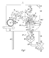
- the collecting cylinder 4 has counter-cutting bars 6, Holding means or holding elements, e.g. B. controlled puncture systems 7 with puncture needles 10 and folding knife 8.
- the collecting cylinder 4 works with a three-field, controlled folding jaw system 9 having folding jaw cylinder 11 together.
- the folding jaw cylinder 11 has a paddle wheel 12 and a delivery belt 13 downstream.
- the folder 1 can also be constructed differently.
- the Counter-cutting bar and collecting cylinder 4 also as a five-field or seven-field Cylinder with a corresponding associated jaw cylinder 11 may be formed.
- the cutting knife cylinder 2 and transport cylinder 4, z. B. Collection cylinder 4 existing cross cutting device are two known pairs of draw rollers 14; 16 upstream.
- the collecting cylinder 4 and the jaw cylinder 11 are nearby its scope not shown paper guide devices, which z. B. from in Production direction exist next to each other spaced guide rails.
- the cylinder fold group 2; 4; 11 and the paddle wheel 12 are in side frames 21, 22 stored.
- the side frames 21; 22 can on underlying machine frames 23; 24 may be arranged.
- a device for treating and in particular for deriving a web or Material web e.g. B. paper web or one consisting of several paper webs
- Paper web strand 26 has before or after a transfer point 17, 18 for signatures 19 a switchable delivery device 27 or 25 to a disposal device 28.
- the transfer point 17 for signatures 19 is located in a gap between cylinder 4 and cylinder 11 and the transfer point 18 is located between cylinder 11 and Paddle wheel 12.
- the switchable delivery device 27 can on the circumference of the cylinder 2 or 4 and Dispensing device 25 can be arranged on the cylinder 11 and by means of control devices be operable.
- the dispenser 27 cannot in the cutting area of the cylinder 2; 4 or in the range the transfer points 17; 18 take effect.
- the dispenser 27 is preferably in the area of the outlet gusset 29 of the cylinders 2; 4; so before the Transfer point 17 at a release point 31 or after the transfer point 18 in one Area e actuated at a release point 32.
- the dispenser 25 consists in this Trap from folding jaw systems controlled in this area 9.
- At the release point 31 of the cylinder 4 (FIG. 3) and 32 of the cylinder 11 (FIG. 1) are each the Holding devices 7 and 9 ineffective, so that the beginning 33 of the paper web strand 26 or the beginning 34 of the signatures 19 of a switchable line or Signature detection and transport device 36 is supplied.
- the holding devices consist of puncture systems 7 Dispensing device 27 of the cylinder 4 is as a stripping device 37 for the needles Puncture systems 7 formed.
- the stripping devices 37 are, in Production direction of rotation of the cylinder 4 seen, each behind the puncture systems 7th arranged and consist of, the puncture needles 10 fork-shaped, d. H. partially comprehensive lifters 40.
- the lifters 40 can also use the puncture needles 10 entirely include, e.g. B. if the lifters have 40 holes through which the Protruding puncture needles 10.
- scraper devices 37 are provided with a side-mounted, pivotable cam segment 38 in connection.
- the signatures 19, i.e. H. the one cut into pieces Paper web 26 by means of the lifter 40 of the stripping device 37 from the puncture needles 10 of the puncture systems 7 pushed down and the disposal device 28 fed (Fig. 1).
- Between the stripping device 37 and the strand or signature detection and Transport device 36 is advantageously a spaced on the circumference of the Collection cylinder 4 in a rest position A - shown in dashed lines - swiveling or in a working position B swivel guide 39 or switchable switch arranged.
- the guide 39 is z. B. from one of the outlet gusset 29 Cross cutting device 2; 4 near part of the paper guide.
- the guide 39 will z. B. actuated by means of a pneumatic working cylinder 41 (FIG. 2) and is one Pivot axis 42 in the aforementioned positions A; B swiveling.
- the ends 43 of the guides 39 remote from the pivot axis cooperate in the working position B. a wedge-shaped narrowing inlet gap 44 between two co-operating endless belt systems 46; 47 the strand or signature acquisition and Transport device 36 together.
- the tape systems 46; 47 are each over Deflection rollers 48; 49; 51; 52 and guide rollers 53; 54 guided, the deflection rollers 49; 52 z. B. are driven by motors.
- Both tape systems 46; 47 are e.g. B. in one not shown frames arranged. This frame is by means of a not shown drive z. B. pneumatic cylinder, from a horizontal Rest position C - shown in dashed lines - around a side frame fixed Pivot axis 42 can be pivoted into a vertical working position D (FIG. 1).
- Signatures 19 are cross-cut and possibly previously longitudinally folded sections of a Paper web strand 26 or a paper web.
- the disposal device 28 consists of a known chopper 56.
- the there shredded signatures 19 are carried out by means of a pipeline 57, optionally via a pipe switch 58 of another pipe 59 or 61 optionally a delivery point 62 for white paper residues or a delivery point 63 printed Paper scraps fed.
- the piping switch 58 can be used to select its position via the machine control station a signal e.g. B. for "pressure-down” or "pressure-on".
- Pipelines and subsequent conveyor belts for transporting the signatures 19 can be assigned to one or several collecting containers. This can be both for both unprinted and printed signatures.
- a method for treating a beginning of a paper web or a signature 19 runs as follows from: Are z. B. new paper webs 26 in a web-fed rotary printing press retracted, the paper webs 26 arrive one after the other and possibly individually in front of the Inlet of the cross cutting device 2; 4 of the folder 1. There are the beginnings 33 of the paper webs 26 continuously the cross cutting device 2; 4 fed with Retaining means 7 and by means of the guide 39 or located in working position B. Switch with the aid of the lifter 40 of the stripping device 37, the in Working position D located belt system 46; 47 fed, d. H. from the usual Production process derived. Generally speaking, the beginning of the Paper web strand 26 of holding means, e.g. B.
- Puncture systems 7 of the cylinder 4th seized or needled and transported.
- the Dispenser 27 If a signal is issued by the machine control center, the Dispenser 27 its activity by changing the position of the cam segment 38 and the switch or guide 39. The strand or Signature detection and transport device 36 assumes its rest position C and the Tape systems 46; 47 are pivoted into their rest position C. The signatures 19 run now in the usual way through the folder 1.
- the collecting cylinder 4 has side disks 71; 72 on which with a shaft 73 are firmly connected.
- the shaft 73 is on both sides via bearings 74; 76 and side frame fixed bearing bushes 77; 78 freely rotatable and by means of a gear 79 drivable (Fig. 4).
- the side windows 71; 72 have three on the circumference Puncture waves 81, which each have the puncture systems 7 with the puncture needles 10 wear. Alternatively, five or seven point waves 81 can also be arranged.
- Each puncture shaft 81 is a lever arm, not shown, and rollers 82; 83 with a known side frame fixed cam 84 for puncture systems 7 and one by means of a gearbox rotatably arranged on the bearing bush 77 Cam 86 - a so-called cover plate - connected.
- the puncture needles 10 comprise stripping devices in the form of a fork 37 on a side-shaft-mounted hollow shaft 87 with an internal one Torsion bar spring arranged.
- z. B. in the outlet gusset 29 of the cross cutting device 2; 4 is the side frame fixed, by an angular amount alpha from a rest position G to a working position F pivotable, segment-shaped cam segment 38 arranged.
- the Cam segment 38 is through with an axis-parallel to the shaft 73 the bearing bush 78 guided shaft 88 via a lever arm 89 with a side frame fixed, hydraulically operating cylinder 91 connected.
- the bearing bush 78 carries a coaxial to the shaft 73 on its side window distal side arranged cylindrical cam 92 with a circumference circular control surface 93. On this control surface 93 runs a roller 94 with a double width tread 96 um. Double width means that the tread 96 with both the control surface 93 as well as with the control surface 35 of the cam segment 38 communicates.
- the roller 94 is connected to the hollow shaft 87 by means of a lever arm 95 connected.
- the working cylinder 91 is double-acting and with a control valve 97 a pressure supply station 98 in connection (Fig. 5).
- the pressure supply station 98 includes e.g. B. a hydraulic pump, a pressure regulator, a check valve, a Hydraulic accumulator and a measuring device.
- the control valve 97 is still means Control lines 99; 101 connected to a control device 102, which in turn both via lines 103; 104 with a computer or control center as well as via a line 106 is connected to a side frame-fixed sensor 107.
- the sensor 107 detects the by means of a cam 109 located on the shaft 108 of the cylinder 2 respective position of the cutting knife 3.
- the control device 102 is connected via the lines 103; 104 signals sent.
- the working cylinder 91 thus receives control valve 97 and a line 111 pressure oil is supplied so that the cam segment 38 of the Rest position G is brought into the working position F.
- the double-width roller 94 already points on the control surface 93 during the rolling process a certain speed, which when driving over the control surface 35 of the Cam segment 38 is advantageously increased only slightly.
- a device for treating, discharging or redirecting signatures 19 or a beginning 33 of a paper web 26 or a paper web strand exists after a further embodiment z. B. from releasable holding means, for. B. from retractable puncture systems 7.
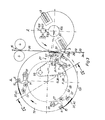
- the puncture systems 7 are located on the Collection cylinder 4 of the first pair of cylinders 2; 117 and are at least in the range of one Outlet gusset 118 by means of a puncture system control 81, 119, 121, 122, 134, 140 arranged retractably within the circumference 137 of the collecting cylinder 117 (FIG. 6).
- the puncture needles 10 are each arranged in a puncture shaft 81 Puncture needle holders 119 held.
- a roller lever attached to each puncture shaft 81 121 carries a double-wide roller 122 at its end.
- Two side windows 123; 124 limit the collecting cylinder 117 on a shaft 126.
- the shaft 126 is on both sides via bearings 127; 128 and side frame fixed bearing bushes 129; 131 freely rotatably mounted and driven by a gear 132 (Fig. 7).
- the roller 122 runs on the one hand on a control surface 133 of the side frame fixed Cam 134 off.
- the control surface 133 is designed so that. H. flattened that the Tip of the puncture needles 10 in the area of a nip 136 between the Cutting knife cylinder 2 and the collecting cylinder 117 within the circumference 137 of the Collection cylinder 117 are retractable.
- inlet gusset 138 and Outlet gusset 118 of the cutting knife cylinder 2 and the collecting cylinder 117 means in the area of an inlet gusset 138 and Outlet gusset 118 of the cutting knife cylinder 2 and the collecting cylinder 117.
- the drivable cover plate 140 (FIG. 6) by about 90 ° against the Turned clockwise, which then with an increase 139 in their control surface 141 covers a flat 142 of the control surface 133.
- the cover plate 140 is fixed arranged on the rotatable bearing bush 129, which carries a ring gear 143.
- On The cover disk 140 is rotated by means of a gear segment 144, which mounted on the side frame so as to be pivotable and by means of a working cylinder 146 in two Positions is adjustable.
- the cutting knives 3 located on the cutting knife cylinder 2 or 116 at least in the area of the nip 136 within the circumference 148 of the Cutting knife cylinder 116 are retracted.
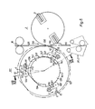
- the illustration 8 are both the puncture needles 10 of the cylinder in the area of the roller gap 136 117 and the cutting knife 3 of the cutting knife cylinder 116 are withdrawn.
- the beginning 33 of the path 26 and subsequently the entire path 26 can Strand or signature detection and transport device 36 and / or the Disposal device 28 are supplied.
- This control body 147 can by means not shown, for. B. Working cylinder at an angle beta, e.g. B. from 90 ° to the outer cutter cylinder 116 are rotated so that the vertical axis 150 of the cross-sectionally oval Control body 147 no longer as shown in FIG. 8, in the direction of rollers 152 points, but in the direction of the cutting knife 3.
- the cutting knives 3 are optionally in the area of the roller gap 136 within the circumference 148 of the cutting knife cylinder 116 (Fig. 8) or in Normal position, d. H. outside the scope 148 - not shown.
- the cutting blades 3 are in each case on both sides by means of two-armed angle levers 149 in Side windows 151 stored. There can be several angle levers 149 per cutting knife 3 be provided.
- a first side of the angle lever 149 carries a roller 152 and a second side of the Angle lever 149 carries the cutting knife 3 in a cutting knife holder 153.
- Die der Cutting edge of the cutting knife 3 is facing away from the cutting knife holder 153 each have a friction-reducing sliding layer 154 with which the Cutting knife holder 153 is supported on the surface of the control body 147.
- the cutting knife cylinder 116 expediently has on its outer surface or Scope 148 brushes 156 with which the paper web strand 26 to the Counter cutting and collecting cylinder 117 is pressed.
Landscapes
- Engineering & Computer Science (AREA)
- Mechanical Engineering (AREA)
- Folding Of Thin Sheet-Like Materials, Special Discharging Devices, And Others (AREA)
- Auxiliary Devices For And Details Of Packaging Control (AREA)
- Separation, Sorting, Adjustment, Or Bending Of Sheets To Be Conveyed (AREA)
- Advancing Webs (AREA)
- Forming Counted Batches (AREA)
- Preliminary Treatment Of Fibers (AREA)
- Credit Cards Or The Like (AREA)
- Orthopedics, Nursing, And Contraception (AREA)
Abstract
Description
- Fig. 1
- eine schematische Darstellung eines Querschnittes durch die Zylindergruppe eines Falzapparates mit einer Vorrichtung;
- Fig. 2
- eine vergrößerte Darstellung der Abgabeeinrichtung, Führung sowie des Einlaufs in die Erfassungs- und Transporteinrichtung;
- Fig. 3
- eine präzisierte Darstellung eines Antriebes der Abgabeeinrichtung;
- Fig. 4
- einen Schnitt IV - IV nach Fig. 3;
- Fig. 5
- eine ausschnittsweise Detaildarstellung des Antriebes und der Steuerung einer Abstreifvorrichtung nach Fig. 2 oder 3;
- Fig. 6
- eine vergrößerte Darstellung eines Schneidzylinders sowie eines Punktur- und Gegenschneidleistenzylinders mit einer weiteren Ausführungsvariante einer Abgabeeinrichtung zum Ausschleusen einer Signatur;
- Fig. 7
- eine Schnitt VII - VII nach Fig. 6;
- Fig. 8
- eine vergrößerte Darstellung eines Schneidzylinders sowie eines Punktur- und Gegenschneidleistenzylinders mit einer weiteren Ausführungsvariante einer Vorrichtung zum Ausschleusen einer Papierbahn.
- 01
- Falzapparat
- 02
- Schneidmesserzylinder (1)
- 03
- Schneidmesser (2)
- 04
- Sammelzylinder (1)
- 05
- -
- 06
- Gegenschneidleisten (4)
- 07
- Halteeinrichtung; Punktursystem (4)
- 08
- Falzmesser (4)
- 09
- Halteeinrichtung; Falzklappensystem (11)
- 10
- Punkturnadel (7)
- 11
- Falzklappenzylinder (1 )
- 12
- Schaufelrad
- 13
- Auslageband
- 14
- Zugwalzenpaar
- 15
- -
- 16
- Zugwalzenpaar
- 17
- Übergabestelle (4; 11)
- 18
- Übergabestelle (11; 12)
- 19
- Signatur
- 20
- -
- 21
- Seitengestell
- 22
- Seitengestell
- 23
- Maschinengestell
- 24
- Maschinengestell
- 25
- Abgabeeinrichtung (11)
- 26
- Papierbahnstrang, Bahn
- 27
- Abgabeeinrichtung (4)
- 28
- Entsorgungseinrichtung
- 29
- Auslaufzwickel (2; 4)
- 30
- Freigabestelle (2)
- 31
- Freigabestelle (4)
- 32
- Freigabestelle (11 )
- 33
- Anfang (26)
- 34
- Anfang (19)
- 35
- Steuerfläche (38)
- 36
- Strang- oder Signaturerfassungs- und Transporteinrichtung
- 37
- Abstreifeinrichtung (7)
- 38
- Kurvenscheiben-Segment (37)
- 39
- Führung, Weiche
- 40
- Ausheber (37)
- 41
- Arbeitszylinder (39)
- 42
- Schwenkachse (39)
- 43
- Ende (39)
- 44
- Einlaufspalt (46; 47)
- 45
- -
- 46
- Bandsystem
- 47
- Bandsystem
- 48
- Umlenkrolle (46)
- 49
- Umlenkrolle (46)
- 50
- -
- 51
- Umlenkrolle (47)
- 52
- Umlenkrolle (47)
- 53
- Leitrolle (46)
- 54
- Leitrolle(47)
- 55
- -
- 56
- Häckselwerk
- 57
- Rohrleitung
- 58
- Rohrleitungsweiche
- 59
- Rohrleitung
- 60
- -
- 61
- Rohrleitung
- 62
- Abgabestelle
- 63
- Abgabestelle
- 64 bis 70
- -
- 71
- Seitenscheibe (4)
- 72
- Seitenscheibe (4)
- 73
- Welle (4)
- 74
- Lager (73)
- 75
- -
- 76
- Lager (73)
- 77
- Lagerbuchse (73)
- 78
- Lagerbuchse (73)
- 79
- Zahnrad (73)
- 80
- -
- 81
- Punkturwelle (7)
- 82
- Laufrolle (81)
- 83
- Laufrolle (81)
- 84
- Kurvenscheibe (7)
- 85
- -
- 86
- Kurvenscheibe
- 87
- Hohlwelle (37)
- 88
- Welle (89)
- 89
- Hebelarm (91)
- 90
- -
- 91
- Arbeitszylinder (38)
- 92
- Kurvenscheibe
- 93
- Steuerfläche (92)
- 94
- Laufrolle
- 95
- Hebelarm (94)
- 96
- Lauffläche (94)
- 97
- Steuerventil
- 98
- Druckversorgungsstation
- 99
- Steuerleitung
- 100
- -
- 101
- Steuerleitung
- 102
- Steuergerät
- 103
- Leitung
- 104
- Leitung
- 105
- -
- 106
- Leitung
- 107
- Sensor
- 108
- Welle (2)
- 109
- Nocken (108)
- 110
- -
- 111
- Leitung (91)
- 112
- Anschlag (89)
- 113
- Anschlag (89)
- 114
- Leitung (91)
- 115
- -
- 116
- Schneidmesserzylinder
- 117
- Sammelzylinder
- 118
- Auslaufzwickel (116, 117; 2, 117)
- 119
- Punkturnadelhalter (10)
- 120
- -
- 121
- Rollenhebel
- 122
- Laufrolle (121)
- 123
- Seitenscheibe (117)
- 124
- Seitenscheibe (117)
- 125
- -
- 126
- Welle (117)
- 127
- Lager
- 128
- Lager
- 129
- Lagerbuchse (127)
- 130
- -
- 131
- Lagerbuchse (128)
- 132
- Zahnrad (126)
- 133
- Steuerfläche (134)
- 134
- Kurvenscheibe
- 135
- -
- 136
- Walzenspalt (2, 117; 116, 117)
- 137
- Umfang (117)
- 138
- Einlaufzwickel
- 139
- Erhöhung (141)
- 140
- Abdeckscheibe
- 141
- Steuerfläche (140)
- 142
- Abflachung (133)
- 143
- Zahnkranz
- 144
- Zahnradsegment
- 145
- -
- 146
- Arbeitszylinder (144)
- 147
- Steuerkörper (116)
- 148
- Umfang (116)
- 149
- Winkelhebel (116)
- 150
- Hochachse (147)
- 151
- Seitenscheibe (116)
- 152
- Laufrolle (116)
- 153
- Schneidmesserhalter
- 154
- Gleitschicht (153)
- 155
- -
- 156
- Bürste
- A
- Ruhestellung (39
- B
- Arbeitsstellung (39)
- C
- Ruhestellung (36)
- D
- Arbeitsstellung (36)
- G
- Ruhestellung (38)
- F
- Arbeitsstellung (38)
- e
- Bereich
- Alpha
- Winkelbetrag (G; F)
- Beta
- Winkel
Claims (4)
- Vorrichtung zum Ausschleusen von Signaturen (19) oder eines Anfanges (33) einer Bahn (26) oder eines Bahnstranges aus einem Falzapparat (2, 4, 11), dadurch gekennzeichnet, dass dem Falzapparat eine Zerkleinerungseinrichtung (56) zugeordnet ist.
- Vorrichtung nach Anspruch 1, dadurch gekennzeichnet, dass die Zerkleinerungseinrichtung (56) als Häckseleinrichtung ausgebildet ist.
- Vorrichtung nach Anspruch 1, dadurch gekennzeichnet, dass die Zerkleinerungseinrichtung (56) in unmittelbarer Nähe eines Zylinders des Falzapparates angeordnet ist.
- Vorrichtung nach Anspruch 1, dadurch gekennzeichnet, dass eine schaltbare Abgabeeinrichtung (27) zu der Zerkleinerungseinrichtung (56) vor einer zwischen einem Sammelzylinder (4) und Falzklappenzylinder (11) angeordneten Übergabestelle (17) für Signaturen (19) vorgesehen ist.
Applications Claiming Priority (3)
| Application Number | Priority Date | Filing Date | Title |
|---|---|---|---|
| DE10018770A DE10018770C1 (de) | 2000-04-15 | 2000-04-15 | Vorrichtung zum Ausschleusen von Signaturen aus einem Falzapparat |
| DE10018770 | 2000-04-15 | ||
| EP01931422A EP1274638B1 (de) | 2000-04-15 | 2001-04-06 | Vorrichtung zum ausschleusen von signaturen aus einem falzapparat |
Related Parent Applications (1)
| Application Number | Title | Priority Date | Filing Date |
|---|---|---|---|
| EP01931422A Division EP1274638B1 (de) | 2000-04-15 | 2001-04-06 | Vorrichtung zum ausschleusen von signaturen aus einem falzapparat |
Publications (2)
| Publication Number | Publication Date |
|---|---|
| EP1486443A1 true EP1486443A1 (de) | 2004-12-15 |
| EP1486443B1 EP1486443B1 (de) | 2008-03-12 |
Family
ID=7638894
Family Applications (2)
| Application Number | Title | Priority Date | Filing Date |
|---|---|---|---|
| EP04102367A Expired - Lifetime EP1486443B1 (de) | 2000-04-15 | 2001-04-06 | Vorrichtung zum Ausschleusen von Signaturen oder eines Anfanges einer Bahn oder eines Bahnstranges aus einem Falzapparat |
| EP01931422A Expired - Lifetime EP1274638B1 (de) | 2000-04-15 | 2001-04-06 | Vorrichtung zum ausschleusen von signaturen aus einem falzapparat |
Family Applications After (1)
| Application Number | Title | Priority Date | Filing Date |
|---|---|---|---|
| EP01931422A Expired - Lifetime EP1274638B1 (de) | 2000-04-15 | 2001-04-06 | Vorrichtung zum ausschleusen von signaturen aus einem falzapparat |
Country Status (7)
| Country | Link |
|---|---|
| US (1) | US6913567B2 (de) |
| EP (2) | EP1486443B1 (de) |
| JP (1) | JP3908035B2 (de) |
| AT (2) | ATE299122T1 (de) |
| AU (1) | AU5820601A (de) |
| DE (3) | DE10018770C1 (de) |
| WO (1) | WO2001079099A2 (de) |
Cited By (1)
| Publication number | Priority date | Publication date | Assignee | Title |
|---|---|---|---|---|
| US8921593B2 (en) | 2010-05-04 | 2014-12-30 | Celanese International Corporation | Process for the semi-continuous transvinylation of carboxylic acids with vinyl acetate |
Families Citing this family (9)
| Publication number | Priority date | Publication date | Assignee | Title |
|---|---|---|---|---|
| US20030047049A1 (en) * | 2001-09-13 | 2003-03-13 | Baker John R. | Method and apparatus for collecting uncut continuous materials and producing chopped continuous materials |
| MX2015017166A (es) | 2013-06-12 | 2016-04-06 | Procter & Gamble | El metodo para perforar una linea de rasgadura no lineal. |
| WO2014201072A1 (en) | 2013-06-12 | 2014-12-18 | The Procter & Gamble Company | A nonlinear line of weakness formed by a perforating apparatus |
| FR3039453B1 (fr) * | 2015-07-31 | 2017-08-11 | Holweg Group | Machine et procede de fabrication de sacs |
| DE102017004370A1 (de) * | 2017-05-05 | 2018-11-08 | Kolbus Gmbh & Co. Kg | Vorrichtung zum Erzeugen von Kollektionen aus bogenförmigen Druckerzeugnissen und Falzapparat |
| WO2019051460A1 (en) | 2017-09-11 | 2019-03-14 | The Procter & Gamble Company | HYGIENIC PAPER HAVING A SHORT LINE OF WEAKNESS |
| US11806889B2 (en) * | 2017-09-11 | 2023-11-07 | The Procter & Gamble Company | Perforating apparatus and method for manufacturing a shaped line of weakness |
| US11806890B2 (en) | 2017-09-11 | 2023-11-07 | The Procter & Gamble Company | Perforating apparatus and method for manufacturing a shaped line of weakness |
| CN113443499B (zh) * | 2021-07-12 | 2022-08-19 | 嘉兴市虹亚纱管纸业有限公司 | 一种纸张自动化整平系统 |
Citations (2)
| Publication number | Priority date | Publication date | Assignee | Title |
|---|---|---|---|---|
| US4166030A (en) * | 1975-08-06 | 1979-08-28 | De La Rue Crosfield Limited | Apparatus for handling sheets of paper |
| DE4301093A1 (de) * | 1992-01-21 | 1993-07-22 | Heidelberger Druckmasch Ag |
Family Cites Families (13)
| Publication number | Priority date | Publication date | Assignee | Title |
|---|---|---|---|---|
| DE2126610A1 (de) * | 1970-07-27 | 1972-02-03 | Polygraph Leipzig | Rotationsfalzapparat |
| JPH0790514B2 (ja) * | 1989-02-20 | 1995-10-04 | 日本ダイスチール株式会社 | 紙器打抜き装置に用いる木型 |
| US5046675A (en) * | 1989-03-02 | 1991-09-10 | Rodriguez Peter A | System and method for cutting and spooling a web of paper |
| US5064180A (en) | 1990-04-09 | 1991-11-12 | Harris Graphics Corporation | Electrostatic diverter |
| DE4125465A1 (de) | 1991-08-01 | 1993-02-04 | Zirkon Druckmaschinen Gmbh | Transportvorrichtung zum ueberfuehren von quergefalzten druckprodukten zum dritten falz |
| DE4241810C2 (de) * | 1992-12-11 | 2001-01-04 | Heidelberger Druckmasch Ag | Formatvariabler Kombinationsfalzapparat |
| US5910079A (en) * | 1992-12-14 | 1999-06-08 | Strapack Corporation | Method and apparatus for manufacturing paper cushioning members |
| JPH07157191A (ja) * | 1993-12-03 | 1995-06-20 | Dainippon Printing Co Ltd | 印刷物折機 |
| DE4438207C2 (de) * | 1994-10-26 | 2002-07-18 | Wilhelm Hogenkamp Verpackungst | Übergabevorrichtung für auf einem umlaufenden endlosen Zuführband in Querreihen ankommenden Gegenstände |
| CA2172082A1 (en) | 1995-03-24 | 1996-09-25 | Carl R. Marschke | Sheet saving diverter for corrugator |
| US5655643A (en) * | 1996-05-08 | 1997-08-12 | United Parcel Service Of America, Inc. | High speed, compound, belted diverter and method of operating same |
| US6019364A (en) * | 1997-11-14 | 2000-02-01 | Bell & Howell Postal Systems Inc. | Mail facing transport system |
| DE10040580A1 (de) * | 2000-08-15 | 2002-02-28 | Heidelberger Druckmasch Ag | Vorrichtung zum Führen von Signaturen, insbesondere im Bereich eines Auslauf-Zwickels einer Schneidzylinderanordnung in einem Falzapparat einer Rotationsdruckmaschine |
-
2000
- 2000-04-15 DE DE10018770A patent/DE10018770C1/de not_active Expired - Fee Related
-
2001
- 2001-04-06 US US10/240,763 patent/US6913567B2/en not_active Expired - Fee Related
- 2001-04-06 AT AT01931422T patent/ATE299122T1/de not_active IP Right Cessation
- 2001-04-06 AU AU58206/01A patent/AU5820601A/en not_active Abandoned
- 2001-04-06 EP EP04102367A patent/EP1486443B1/de not_active Expired - Lifetime
- 2001-04-06 JP JP2001576369A patent/JP3908035B2/ja not_active Expired - Fee Related
- 2001-04-06 DE DE50113740T patent/DE50113740D1/de not_active Expired - Lifetime
- 2001-04-06 WO PCT/DE2001/001347 patent/WO2001079099A2/de not_active Ceased
- 2001-04-06 EP EP01931422A patent/EP1274638B1/de not_active Expired - Lifetime
- 2001-04-06 AT AT04102367T patent/ATE388920T1/de not_active IP Right Cessation
- 2001-04-06 DE DE50106693T patent/DE50106693D1/de not_active Expired - Fee Related
Patent Citations (2)
| Publication number | Priority date | Publication date | Assignee | Title |
|---|---|---|---|---|
| US4166030A (en) * | 1975-08-06 | 1979-08-28 | De La Rue Crosfield Limited | Apparatus for handling sheets of paper |
| DE4301093A1 (de) * | 1992-01-21 | 1993-07-22 | Heidelberger Druckmasch Ag |
Cited By (2)
| Publication number | Priority date | Publication date | Assignee | Title |
|---|---|---|---|---|
| US8921593B2 (en) | 2010-05-04 | 2014-12-30 | Celanese International Corporation | Process for the semi-continuous transvinylation of carboxylic acids with vinyl acetate |
| US8975437B2 (en) | 2010-05-04 | 2015-03-10 | Celanese International Corporation | Process for the continuous transvinylation of carboxylic acids with vinyl acetate |
Also Published As
| Publication number | Publication date |
|---|---|
| EP1274638A2 (de) | 2003-01-15 |
| WO2001079099B1 (de) | 2002-07-18 |
| DE50106693D1 (de) | 2005-08-11 |
| ATE299122T1 (de) | 2005-07-15 |
| US6913567B2 (en) | 2005-07-05 |
| AU5820601A (en) | 2001-10-30 |
| EP1274638B1 (de) | 2005-07-06 |
| JP2003531082A (ja) | 2003-10-21 |
| DE10018770C1 (de) | 2001-10-31 |
| WO2001079099A2 (de) | 2001-10-25 |
| DE50113740D1 (de) | 2008-04-24 |
| JP3908035B2 (ja) | 2007-04-25 |
| ATE388920T1 (de) | 2008-03-15 |
| US20030106405A1 (en) | 2003-06-12 |
| WO2001079099A3 (de) | 2002-04-11 |
| EP1486443B1 (de) | 2008-03-12 |
Similar Documents
| Publication | Publication Date | Title |
|---|---|---|
| DE10018772C2 (de) | Vorrichtung zum Querschneiden von mindestens einer Bahn in einem Falzapparat einer Rotationsdruckmaschine | |
| DE10018770C1 (de) | Vorrichtung zum Ausschleusen von Signaturen aus einem Falzapparat | |
| EP1930162B1 (de) | Vorrichtungen und Verfahren zum Einziehen mindestens einer Materialbahn bzw. von mindestens einem Bahnstrang in einen Falzapparat | |
| DE60222069T2 (de) | Eine Abgabeeinheit für eine Zigarettenherstellungsmaschine | |
| DE4425662C1 (de) | Vorrichtung zum Quertrennen einer Papierbahn | |
| DE8423786U1 (de) | Vorrichtung zum Aufwickeln einer kontinuierlich zugeführten, flexiblen Warenbahn | |
| WO2001079100A2 (de) | Vorrichtungen zum transportieren einer bahn oder von signaturen in einem falzapparat | |
| DE10059191B4 (de) | Vorrichtung zum Splitten eines von einer Falzgruppe kommenden Stromes von Produkten | |
| EP1401749B1 (de) | Verfahren zum zusammenführen von materialbahnen und vorrichtung zur durchführung dieses verfahrens | |
| DE20022734U1 (de) | Vorrichtung zum Transportieren von Signaturen in einem Falzapparat | |
| EP0997418B1 (de) | Verfahren zum Durchtrennen einer laufenden Materialbahn und Vorrichtung zur Durchführung des Verfahrens | |
| EP0734988B1 (de) | Verfahren und Einrichtung zum Bewegen von Punkturnadeln | |
| DE10128820B4 (de) | Verfahren und Einrichtung zum Einziehen einer Materialbahn | |
| DE69801153T2 (de) | Vorrichtung zum zuführen eines filmes zu einer maschine zum verpacken von gegenständen | |
| EP1732833B1 (de) | Verfahren und vorrichtungen zum kappen und/oder zuführen eines stranges in eine weiterverarbeitungsstufe | |
| DE3222649A1 (de) | Vorrichtung zur behandlung oder bearbeitung eines papierblattbuendels | |
| EP1232983B1 (de) | Vorrichtung zum Führen flächiger Exemplare in Falzapparaten | |
| DE102006016264B4 (de) | Verfahren zur Einstellung eines Falzklappen-Arbeitsabstandes in einem Falzapparat | |
| EP1457329B1 (de) | Verlagerbarer Falzmesserzylinder | |
| DE10209213A1 (de) | Transportvorrichtung | |
| EP1657198A2 (de) | Verfahren und Vorrichtung zum Kappen und/oder Zuführen eines Stranges in eine Weiterverarbeitungsstufe sowie Strangverarbeitungssystem | |
| EP1683752A1 (de) | Vorrichtung zum Querschneiden einer Materialbahn in einzelne Materialabschnitte | |
| DE2126610A1 (de) | Rotationsfalzapparat | |
| DE2513243A1 (de) | Stapelausleger fuer eine rotations (schnelldruck)presse | |
| DE19518430A1 (de) | Verfahren und Einrichtung zum Bewegen von Punkturnadeln |
Legal Events
| Date | Code | Title | Description |
|---|---|---|---|
| PUAI | Public reference made under article 153(3) epc to a published international application that has entered the european phase |
Free format text: ORIGINAL CODE: 0009012 |
|
| AC | Divisional application: reference to earlier application |
Ref document number: 1274638 Country of ref document: EP Kind code of ref document: P |
|
| AK | Designated contracting states |
Kind code of ref document: A1 Designated state(s): AT BE CH CY DE DK ES FI FR GB GR IE IT LI LU MC NL PT SE TR |
|
| 17P | Request for examination filed |
Effective date: 20041030 |
|
| AKX | Designation fees paid |
Designated state(s): AT BE CH CY DE DK ES FI FR GB GR IE IT LI LU MC NL PT SE TR |
|
| GRAP | Despatch of communication of intention to grant a patent |
Free format text: ORIGINAL CODE: EPIDOSNIGR1 |
|
| GRAS | Grant fee paid |
Free format text: ORIGINAL CODE: EPIDOSNIGR3 |
|
| GRAA | (expected) grant |
Free format text: ORIGINAL CODE: 0009210 |
|
| AC | Divisional application: reference to earlier application |
Ref document number: 1274638 Country of ref document: EP Kind code of ref document: P |
|
| AK | Designated contracting states |
Kind code of ref document: B1 Designated state(s): AT BE CH CY DE DK ES FI FR GB GR IE IT LI LU MC NL PT SE TR |
|
| REG | Reference to a national code |
Ref country code: GB Ref legal event code: FG4D Free format text: NOT ENGLISH |
|
| REG | Reference to a national code |
Ref country code: CH Ref legal event code: EP |
|
| REG | Reference to a national code |
Ref country code: IE Ref legal event code: FG4D Free format text: LANGUAGE OF EP DOCUMENT: GERMAN |
|
| GBT | Gb: translation of ep patent filed (gb section 77(6)(a)/1977) |
Effective date: 20080328 |
|
| REF | Corresponds to: |
Ref document number: 50113740 Country of ref document: DE Date of ref document: 20080424 Kind code of ref document: P |
|
| PG25 | Lapsed in a contracting state [announced via postgrant information from national office to epo] |
Ref country code: FI Free format text: LAPSE BECAUSE OF FAILURE TO SUBMIT A TRANSLATION OF THE DESCRIPTION OR TO PAY THE FEE WITHIN THE PRESCRIBED TIME-LIMIT Effective date: 20080312 |
|
| NLV1 | Nl: lapsed or annulled due to failure to fulfill the requirements of art. 29p and 29m of the patents act | ||
| ET | Fr: translation filed | ||
| REG | Reference to a national code |
Ref country code: IE Ref legal event code: FD4D |
|
| BERE | Be: lapsed |
Owner name: KOENIG & BAUER A.G. Effective date: 20080430 |
|
| PG25 | Lapsed in a contracting state [announced via postgrant information from national office to epo] |
Ref country code: SE Free format text: LAPSE BECAUSE OF FAILURE TO SUBMIT A TRANSLATION OF THE DESCRIPTION OR TO PAY THE FEE WITHIN THE PRESCRIBED TIME-LIMIT Effective date: 20080612 Ref country code: ES Free format text: LAPSE BECAUSE OF FAILURE TO SUBMIT A TRANSLATION OF THE DESCRIPTION OR TO PAY THE FEE WITHIN THE PRESCRIBED TIME-LIMIT Effective date: 20080623 Ref country code: PT Free format text: LAPSE BECAUSE OF FAILURE TO SUBMIT A TRANSLATION OF THE DESCRIPTION OR TO PAY THE FEE WITHIN THE PRESCRIBED TIME-LIMIT Effective date: 20080818 |
|
| PG25 | Lapsed in a contracting state [announced via postgrant information from national office to epo] |
Ref country code: MC Free format text: LAPSE BECAUSE OF NON-PAYMENT OF DUE FEES Effective date: 20080430 Ref country code: NL Free format text: LAPSE BECAUSE OF FAILURE TO SUBMIT A TRANSLATION OF THE DESCRIPTION OR TO PAY THE FEE WITHIN THE PRESCRIBED TIME-LIMIT Effective date: 20080312 |
|
| PLBE | No opposition filed within time limit |
Free format text: ORIGINAL CODE: 0009261 |
|
| STAA | Information on the status of an ep patent application or granted ep patent |
Free format text: STATUS: NO OPPOSITION FILED WITHIN TIME LIMIT |
|
| PG25 | Lapsed in a contracting state [announced via postgrant information from national office to epo] |
Ref country code: DK Free format text: LAPSE BECAUSE OF FAILURE TO SUBMIT A TRANSLATION OF THE DESCRIPTION OR TO PAY THE FEE WITHIN THE PRESCRIBED TIME-LIMIT Effective date: 20080312 Ref country code: IE Free format text: LAPSE BECAUSE OF FAILURE TO SUBMIT A TRANSLATION OF THE DESCRIPTION OR TO PAY THE FEE WITHIN THE PRESCRIBED TIME-LIMIT Effective date: 20080312 |
|
| 26N | No opposition filed |
Effective date: 20081215 |
|
| PG25 | Lapsed in a contracting state [announced via postgrant information from national office to epo] |
Ref country code: BE Free format text: LAPSE BECAUSE OF NON-PAYMENT OF DUE FEES Effective date: 20080430 |
|
| PG25 | Lapsed in a contracting state [announced via postgrant information from national office to epo] |
Ref country code: AT Free format text: LAPSE BECAUSE OF NON-PAYMENT OF DUE FEES Effective date: 20080406 Ref country code: IT Free format text: LAPSE BECAUSE OF FAILURE TO SUBMIT A TRANSLATION OF THE DESCRIPTION OR TO PAY THE FEE WITHIN THE PRESCRIBED TIME-LIMIT Effective date: 20080312 |
|
| PG25 | Lapsed in a contracting state [announced via postgrant information from national office to epo] |
Ref country code: CY Free format text: LAPSE BECAUSE OF FAILURE TO SUBMIT A TRANSLATION OF THE DESCRIPTION OR TO PAY THE FEE WITHIN THE PRESCRIBED TIME-LIMIT Effective date: 20080312 |
|
| PG25 | Lapsed in a contracting state [announced via postgrant information from national office to epo] |
Ref country code: LU Free format text: LAPSE BECAUSE OF NON-PAYMENT OF DUE FEES Effective date: 20080406 |
|
| PG25 | Lapsed in a contracting state [announced via postgrant information from national office to epo] |
Ref country code: TR Free format text: LAPSE BECAUSE OF FAILURE TO SUBMIT A TRANSLATION OF THE DESCRIPTION OR TO PAY THE FEE WITHIN THE PRESCRIBED TIME-LIMIT Effective date: 20080312 |
|
| PG25 | Lapsed in a contracting state [announced via postgrant information from national office to epo] |
Ref country code: GR Free format text: LAPSE BECAUSE OF FAILURE TO SUBMIT A TRANSLATION OF THE DESCRIPTION OR TO PAY THE FEE WITHIN THE PRESCRIBED TIME-LIMIT Effective date: 20080613 |
|
| PGFP | Annual fee paid to national office [announced via postgrant information from national office to epo] |
Ref country code: CH Payment date: 20110502 Year of fee payment: 11 |
|
| PGFP | Annual fee paid to national office [announced via postgrant information from national office to epo] |
Ref country code: DE Payment date: 20120622 Year of fee payment: 12 |
|
| PGFP | Annual fee paid to national office [announced via postgrant information from national office to epo] |
Ref country code: FR Payment date: 20120510 Year of fee payment: 12 Ref country code: GB Payment date: 20120425 Year of fee payment: 12 |
|
| REG | Reference to a national code |
Ref country code: CH Ref legal event code: PL |
|
| PG25 | Lapsed in a contracting state [announced via postgrant information from national office to epo] |
Ref country code: CH Free format text: LAPSE BECAUSE OF NON-PAYMENT OF DUE FEES Effective date: 20120430 Ref country code: LI Free format text: LAPSE BECAUSE OF NON-PAYMENT OF DUE FEES Effective date: 20120430 |
|
| GBPC | Gb: european patent ceased through non-payment of renewal fee |
Effective date: 20130406 |
|
| PG25 | Lapsed in a contracting state [announced via postgrant information from national office to epo] |
Ref country code: GB Free format text: LAPSE BECAUSE OF NON-PAYMENT OF DUE FEES Effective date: 20130406 Ref country code: DE Free format text: LAPSE BECAUSE OF NON-PAYMENT OF DUE FEES Effective date: 20131101 |
|
| REG | Reference to a national code |
Ref country code: FR Ref legal event code: ST Effective date: 20131231 |
|
| REG | Reference to a national code |
Ref country code: DE Ref legal event code: R119 Ref document number: 50113740 Country of ref document: DE Effective date: 20131101 |
|
| PG25 | Lapsed in a contracting state [announced via postgrant information from national office to epo] |
Ref country code: FR Free format text: LAPSE BECAUSE OF NON-PAYMENT OF DUE FEES Effective date: 20130430 |