EP1482276A2 - Vibratoreinheit - Google Patents
Vibratoreinheit Download PDFInfo
- Publication number
- EP1482276A2 EP1482276A2 EP20040012702 EP04012702A EP1482276A2 EP 1482276 A2 EP1482276 A2 EP 1482276A2 EP 20040012702 EP20040012702 EP 20040012702 EP 04012702 A EP04012702 A EP 04012702A EP 1482276 A2 EP1482276 A2 EP 1482276A2
- Authority
- EP
- European Patent Office
- Prior art keywords
- section
- vibrator
- elastic mechanism
- supporting
- arm
- Prior art date
- Legal status (The legal status is an assumption and is not a legal conclusion. Google has not performed a legal analysis and makes no representation as to the accuracy of the status listed.)
- Withdrawn
Links
Images


Classifications
-
- G—PHYSICS
- G01—MEASURING; TESTING
- G01C—MEASURING DISTANCES, LEVELS OR BEARINGS; SURVEYING; NAVIGATION; GYROSCOPIC INSTRUMENTS; PHOTOGRAMMETRY OR VIDEOGRAMMETRY
- G01C19/00—Gyroscopes; Turn-sensitive devices using vibrating masses; Turn-sensitive devices without moving masses; Measuring angular rate using gyroscopic effects
- G01C19/56—Turn-sensitive devices using vibrating masses, e.g. vibratory angular rate sensors based on Coriolis forces
Definitions
- the present invention relates to a vibrator unit and, more particularly, to a supporting mechanism for supporting a vibrator such as a gyro vibrator for detecting the orientation, speed, and posture of an object, and to including the vibrator and the supporting mechanism.
- the gyro vibrator described above has a support section for supporting a drive section and a detection section.
- a Coriolis force is applied to the drive section in accordance with a rotation applied thereto while the drive section is vibrating along a certain direction.
- the detection section vibrates in accordance with the Coriolis force to detect the Coriolis force.
- the gyro vibrator is mounted on a substrate with the supporting section being supported by a supporting mechanism provided on the substrate.
- the supporting mechanism described above rigidly supports the gyro vibrator, it is problematical that the vibration of the drive section or the detection section of the gyro vibrator is limited or inhibited. In addition, if the rigidity of the supporting mechanism is lowered to avoid vibration being inhibited, there is caused a problem of lowering reliability such as a shock proof property.
- the vibrator unit 100 is mounted on an object such as an electronic device or a vehicle to detect the orientation, speed, and posture of the object.
- the vibrator unit 100 comprises a gyro vibrator 10, lead wires 15A, 15B, 16A, and 16B forming a supporting mechanism for supporting the gyro vibrator 10, and a supporting substrate 17 for mounting the gyro vibrator 10 via the lead wires 15A and others.
- the gyro vibrator 10 includes, as shown in FIG. 1(A), a first drive arm 11A and a second drive arm 11 B forming together a drive section, a detection arm 12 as a detection section, an arm supporting section 13, and a supporting board 14 as a supporting section so as to act in three modes known as drive mode, detection mode, and spurious mode.
- X, Y and Z in the following text refer to axes of a Cartesian coordinate system as defined in the Figures.
- the first and the second drive arms 11A, 11 B are, as shown in FIG. 1(A), board like members parallel to each other and each elongated in the Y direction to a predetermined length. If rotation around the Z axis, that is one of changes in the orientation of the object mentioned above, is applied while the first and the second drive arms 11 A, 11 B are vibrating along the X direction, the first and the second drive arms 11A, 11B are effected by the Coriolis force corresponding to the amount of the rotation.
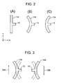
- FIG. 2 shows a resulting deformation of the drive arms.
- the drive arm 11A vibrates so as to bend around its center in the longitudinal direction thereof. More specifically, the drive arm 11A is alternately deformed to a convex shape and a concave shape while vibrating, namely, the opposite longitudinal ends of the drive arm are displaced along the X axis relative to the longitudinal center of the drive arm 11A.
- the drive arm 11B vibrates correspondingly such that its shape becomes axisymmetrical to that of the drive arm 11A.
- FIG. 3 shows the relationship between the deformation of the drive arm and the Coriolis force.
- the first drive arm 11A deforms from the shape illustrated by a broken line to the shape illustrated by a solid line
- the second drive arm 11 B also deforms from the shape illustrated by a broken line to the shape illustrated by a solid line
- they are subjected to the Coriolis force along the arrows 19A and 19B, respectively, in response to a clockwise rotation in the plane of the drawing.
- the Coriolis force acts in directions opposite to the arrows 19A and 19B in response to the same clockwise rotation.
- the detection arm 12 is, similar to the first drive arm 11 A and the second drive arm 11B, a board member having the predetermined length and extending in the Y direction as shown in the drawing. Namely, the first drive arm 11 A, the second drive arm 11 B, and the detection arm 12 are parallel to each other. In response to the Coriolis force acting on the first and the second drive arm 11A, 11B, the detection arm 12 vibrates with an amplitude corresponding to the strength of the Coriolis force.
- FIG. 4 shows a deformation of the detection arm.
- the detection arm 12 performs a bending action by which it is deformed to a shape like the letter "S” and the reverse of the letter “S” as is the case with the bending actions of the first and the second drive arms 11A, 11B shown in FIGS. 3(A) through 3(C).
- the Coriolis force is sensed by detecting an electric signal generated by the rotational bending action of the detection arm 12, thus obtaining a measure of the speed of the rotation applied to the object.
- one end of the arm supporting section 13 is connected to the center of the first drive arm 11A and the other end thereof is connected to the center of the second drive arm 11 B while the detection arm 12 is connected thereto with its center corresponding to the center of the arm supporting section 13.
- the supporting board 14 is a board like member having a predetermined area including the connecting point of the arm supporting section 13 and the detection arm 12.
- the lead wires 15A, 15B extending in the X direction and the lead wires 16A and 16B extending in the Y direction are strip like members all having the same shape. Further, one end of each of the lead wires 15A, 15B is, as shown in FIG. 1 (B), connected to the lower side of the supporting board 14 and the other end is connected to the supporting substrate 17, and the lead wires are formed so as to prevent the vibrator 10 and the supporting substrate 17 from abutting on each other.
- the supporting substrate 17 is, for example, a substrate made of an insulating material such as polyimide resin and has an opening for use of forming the lead wires 15A and so on in its center.
- the lead wires 15A and 15B provided along the X direction are made of a material which makes the characteristic resonance frequency thereof lower than that of the lead wires 16A and 16B provided along the Y direction. Namely, the stiffness of the lead wires 15A and 15B in supporting the gyro vibrator 10 in the X direction is lower than the stiffness of the lead wires 16A and 16B in supporting the gyro vibrator 10 in the Y direction.
- the vibrator unit of the first embodiment since the supporting mechanism has a characteristic resonance frequency in the X direction lower than that in the Y direction, the vibration of the detection arm 12 along the X direction necessary for detecting the Coriolis force applied to the drive arms 11A, 11B can be prevented from being hindered, thus enabling detection of the speed of rotation applied to the object from outside with greater accuracy than is possible in the prior art.
- FIGS. 5(A) and 5(B) show a vibrator unit according to a second embodiment.
- a gyro vibrator 20 according to the second embodiment comprises a first drive arm 21A, a second drive arm 21 B, a detection arm 22, an arm supporting section 23, and a supporting board 24 respectively having substantially the same function as the first drive arm 11A, the second drive arm 11 B, the detection arm 12, the arm supporting section 13, and the supporting board 14 forming the gyro vibrator 10 shown in FIG. 1 (A).
- the gyro vibrator 20 is supported by lead wires 25A and 25B in the X direction and by lead wires 26A and 26B in the Y direction as is the case with the gyro vibrator 10 in which the supporting board 14 is supported by the lead wires 15A, 15B, 16A, and 16B.
- the width of the lead wires 25A and 25B forming a second elastic mechanism is narrower then that of the lead wires 26A and 26B forming a first elastic mechanism.
- FIG. 5(B) Another gyro vibrator 30 according to the second embodiment, as shown in FIG. 5(B), comprises a first drive arm 31 A, a second drive arm 31 B, a detection arm 32, an arm supporting section 33, and a supporting board 34 respectively having substantially the same function as the first drive arm 11A, the second drive arm 11 B, the detection arm 12, the arm supporting section 13, and the supporting board 14 forming the gyro vibrator 10 shown in FIG. 1(A).
- the gyro vibrator 30 is supported only by lead wires 35A, 35B, 36A, and 36B in the Y direction as is the case with the gyro vibrator 10 in which the supporting board 14 is supported in the Y direction by the lead wires 16A, and 16B, and is not supported in the X direction.
- the detection arm 32 is not at all prevented from vibrating in the X direction to detect the Coriolis force acting on the drive arms 31A and 31B.
- the vibrator unit of the second embodiment since the gyro vibrator 20 is supported by the lead wires 26A and 26B in the Y direction and is supported in the X direction by the lead wires 25A and 25B having a characteristic resonance frequency lower than that of the lead wires 26A and 26B, the vibration of the detection arm 22 along the X direction is not hindered as is the case with the detection arm 12 of the vibrator unit 10 according to the first embodiment, thus enabling detection of the speed of rotation applied from outside with greater accuracy than the convention.
- the gyro vibrator 30 is supported only in the Y direction by the lead wires 35A, 35B, 36A, and 36B and is not supported in the X direction, namely there is no limitation in moving in the X direction, the vibration of the detection arm 32 along the X direction is not hindered, thus, as a result, enabling detection of the amplitude of rotation applied from outside with greater accuracy compared to the convention.
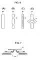
- FIGS. 6(A) trough 6(D) show structures of lead wires for supporting a gyro vibrator according to a third embodiment.
- a lead wire 40 having substantially the same function as the lead wire 15A in the first embodiment has a thickness (the dimension perpendicular to the plane of the drawing sheet) smaller than that of the lead wire 15A.
- a lead wire 50 having substantially the same function as the lead wire 15A in the first embodiment has at least one section along its longitudinal direction that is narrower than the remaining part.
- the width of the lead wire 50 is uneven since the narrower section has a width different from that of the rest.
- a concave shape as shown in the drawing or a wedge shape can be cited.
- a lead wire 60 having substantially the same function as the lead wire 15A in the first embodiment has a hollow section 61 along the longitudinal direction.
- a lead wire 70 having substantially the same function as the lead wire 15A in the first embodiment has a rhombic opening 71 at the center thereof instead of the hollow section 61 along the longitudinal direction.
- the vibrator unit having the lead wires of the third embodiment since the gyro vibrator is supported by the lead wires 40, 50, 60, or 70 having structures easy to be bent, the vibration for detecting of the detection arm is not hindered, thus enabling detection of the amplitude of rotation applied from outside with greater accuracy compared to the convention.
- FIG. 7 is a cross-sectional view showing a structure of a vibrator unit according to a fourth embodiment.
- the vibrator unit of the fourth embodiment comprises a gyro vibrator 72, lead wires 75A and 75B, and a supporting substrate 77 respectively having substantially the same functions as the gyro vibrator 10, the lead wires 15A and 15B, and the supporting substrate 17 shown in FIG. 1 (B) of the first embodiment.
- the lead wires 75A and 75B are bent to a shape substantially like that of the letter "Z", and lead wires (not shown) corresponding to the lead wires 16A and 16B of the first embodiment are bent likewise.
- the bending shape can be obtained by, for example, pushing down the gyro vibrator 70 towards the supporting substrate 77 after mounting the gyro vibrator 70 on the lead wires 75A and 75B fixed to the supporting substrate 77.
- FIG. 8 is a plan view showing a structure of another vibrator unit according to the fourth embodiment.
- gyro vibrator 80 of the fourth embodiment comprises a first drive arm 81 A, a second drive arm 81 B, a detection arm 82, an arm supporting section 83, and a supporting board 84 respectively having substantially the same functions as the first drive arm 11A, the second drive arm 11 B, the detection arm 12, the arm supporting section 13, and the supporting board 14 forming the gyro vibrator 10 shown in FIG. 1(A).
- the gyro vibrator 80 is supported by lead wires 85A and 85B in the X direction and lead wires 86A and 86B in the Y direction as is the case with the gyro vibrator 10 in which the supporting board 14 is supported by the lead wires 15A, 15B, 16A, and 16B.
- the lead wires 85A, 85B, 86A, and 86B are bent to a shape substantially like that of the letter "Z.” That is, in contrast to the lead wires 75A and 75B bent vertically, the lead wires 85A, 85B, 86A, and 86B are bent horizontally.
- the lead wires 75A, 85A and others are bent, the characteristic resonance frequencies of those lead wires are lower than those of conventional lead wires without bent shapes.
- the vibration of the detection arm along the X direction necessary for detecting the Coriolis force acting on the drive arms can be prevented from being hindered, the speed of rotation applied from outside can be detected with greater accuracy compared to the prior art.
- the characteristic resonance frequency of vibration along at least one of the first and the second directions is lower than the characteristic resonance frequency of vibration along a direction other than the at least one of the first and the second directions. Therefore, the supporting mechanism can support the vibrator without limiting or inhibiting the vibration of the vibrator along the at least one of the first and the second directions while maintaining the reliability such as a shock proof property by using the elastic mechanism having the relatively high characteristic resonance frequency in the at least one of the first and the second directions.
Applications Claiming Priority (2)
| Application Number | Priority Date | Filing Date | Title |
|---|---|---|---|
| JP2003151295 | 2003-05-28 | ||
| JP2003151295A JP4389480B2 (ja) | 2003-05-28 | 2003-05-28 | 振動子の支持機構及び振動子ユニット |
Publications (2)
| Publication Number | Publication Date |
|---|---|
| EP1482276A2 true EP1482276A2 (de) | 2004-12-01 |
| EP1482276A3 EP1482276A3 (de) | 2005-06-29 |
Family
ID=33128256
Family Applications (1)
| Application Number | Title | Priority Date | Filing Date |
|---|---|---|---|
| EP04012702A Withdrawn EP1482276A3 (de) | 2003-05-28 | 2004-05-28 | Vibratoreinheit |
Country Status (5)
| Country | Link |
|---|---|
| US (1) | US7000472B2 (de) |
| EP (1) | EP1482276A3 (de) |
| JP (1) | JP4389480B2 (de) |
| KR (1) | KR100618720B1 (de) |
| CN (1) | CN100356138C (de) |
Families Citing this family (20)
| Publication number | Priority date | Publication date | Assignee | Title |
|---|---|---|---|---|
| WO2005047820A1 (ja) * | 2003-11-12 | 2005-05-26 | Ngk Insulators, Ltd. | 振動子の支持部材 |
| JP3864952B2 (ja) * | 2003-12-01 | 2007-01-10 | セイコーエプソン株式会社 | 振動子デバイス及びそれを備えた電子機器並びに振動子デバイスの製造方法 |
| KR100618342B1 (ko) * | 2004-07-29 | 2006-09-04 | 삼성전자주식회사 | 소형 구조물 및 그 제작방법 |
| JP4381354B2 (ja) * | 2004-09-10 | 2009-12-09 | セイコーエプソン株式会社 | 振動子の支持構造および物理量測定装置 |
| JP4428309B2 (ja) * | 2004-09-10 | 2010-03-10 | セイコーエプソン株式会社 | 振動型ジャイロスコープ |
| JP4415382B2 (ja) * | 2005-01-20 | 2010-02-17 | セイコーエプソン株式会社 | 振動ジャイロ素子、振動ジャイロ素子の支持構造およびジャイロセンサ |
| JP4682671B2 (ja) * | 2005-03-31 | 2011-05-11 | セイコーエプソン株式会社 | 圧電デバイス |
| JP4442526B2 (ja) * | 2005-07-20 | 2010-03-31 | セイコーエプソン株式会社 | 圧電振動ジャイロセンサ及び圧電振動ジャイロセンサを備えた電子機器 |
| WO2007080908A1 (ja) * | 2006-01-13 | 2007-07-19 | Citizen Holdings Co., Ltd. | 角速度センサー用振動体 |
| JP2007285977A (ja) * | 2006-04-19 | 2007-11-01 | Fujitsu Media Device Kk | 角速度センサ |
| JP4850572B2 (ja) * | 2006-04-19 | 2012-01-11 | 富士通株式会社 | 角速度センサ |
| JP5622347B2 (ja) | 2006-08-09 | 2014-11-12 | セイコーエプソン株式会社 | 慣性センサ装置 |
| JP2010002427A (ja) * | 2006-08-09 | 2010-01-07 | Epson Toyocom Corp | 慣性センサ、慣性センサ装置及びその製造方法 |
| WO2010029656A2 (en) * | 2008-09-10 | 2010-03-18 | Panasonic Corporation | Mems device and method for manufacturing the same |
| JP2010169457A (ja) * | 2009-01-21 | 2010-08-05 | Epson Toyocom Corp | 圧電振動片および物理量検出装置 |
| JP2010190706A (ja) * | 2009-02-18 | 2010-09-02 | Panasonic Corp | 慣性力センサ |
| JP2011145278A (ja) * | 2009-12-16 | 2011-07-28 | Seiko Epson Corp | 振動片、振動子、物理量センサー、および電子機器 |
| JP5257440B2 (ja) * | 2010-12-08 | 2013-08-07 | セイコーエプソン株式会社 | 圧電デバイス |
| JP5765993B2 (ja) * | 2011-03-31 | 2015-08-19 | キヤノン株式会社 | 振動型駆動装置 |
| JP7183902B2 (ja) * | 2019-03-25 | 2022-12-06 | セイコーエプソン株式会社 | 振動デバイス、電子機器および移動体 |
Citations (3)
| Publication number | Priority date | Publication date | Assignee | Title |
|---|---|---|---|---|
| EP0915322A2 (de) | 1997-11-04 | 1999-05-12 | Ngk Insulators, Ltd. | Vibratoren, Vibrationskreisel, Vorrichtungen zur Messung einer linearen Beschleunigung sowie ein Verfahren zur Messung einer Winkelgeschwindigkeit |
| EP0930482A2 (de) | 1997-10-06 | 1999-07-21 | Ngk Insulators, Ltd. | Vibrationskreisel |
| EP1333289A1 (de) * | 2002-01-30 | 2003-08-06 | Ngk Insulators, Ltd. | System und Struktur zur Halterung eines Schwingers |
Family Cites Families (9)
| Publication number | Priority date | Publication date | Assignee | Title |
|---|---|---|---|---|
| JPH03198003A (ja) | 1989-12-27 | 1991-08-29 | Ricoh Co Ltd | マイクロレンズアレイの製造方法 |
| KR100525642B1 (ko) | 1996-09-19 | 2005-11-02 | 세이코 엡슨 가부시키가이샤 | 유기 반도체막의 형성 방법 및 발광소자의 제조 방법 |
| DE69832843T2 (de) * | 1997-05-28 | 2006-07-27 | Murata Mfg. Co., Ltd., Nagaokakyo | Vibrationskreisel |
| US6205857B1 (en) * | 1998-02-25 | 2001-03-27 | Citizen Watch Co., Ltd. | Angular velocity sensing device |
| JP4364385B2 (ja) * | 1999-02-17 | 2009-11-18 | 日本碍子株式会社 | 振動型ジャイロスコープおよびその製造方法 |
| JP3999452B2 (ja) * | 1999-09-30 | 2007-10-31 | 日本碍子株式会社 | 振動型ジャイロスコープ |
| JP2001255152A (ja) | 2000-03-07 | 2001-09-21 | Nec Corp | 圧電振動ジャイロスコープおよびその周波数調整方法 |
| JP2002181550A (ja) * | 2000-10-02 | 2002-06-26 | Ngk Insulators Ltd | 角速度測定装置 |
| JP4305623B2 (ja) * | 2002-03-13 | 2009-07-29 | セイコーエプソン株式会社 | 振動子および振動型ジャイロスコープ |
-
2003
- 2003-05-28 JP JP2003151295A patent/JP4389480B2/ja not_active Expired - Lifetime
-
2004
- 2004-05-27 KR KR1020040037934A patent/KR100618720B1/ko active IP Right Grant
- 2004-05-28 CN CNB200410045554XA patent/CN100356138C/zh not_active Expired - Fee Related
- 2004-05-28 EP EP04012702A patent/EP1482276A3/de not_active Withdrawn
- 2004-05-28 US US10/857,066 patent/US7000472B2/en active Active
Patent Citations (3)
| Publication number | Priority date | Publication date | Assignee | Title |
|---|---|---|---|---|
| EP0930482A2 (de) | 1997-10-06 | 1999-07-21 | Ngk Insulators, Ltd. | Vibrationskreisel |
| EP0915322A2 (de) | 1997-11-04 | 1999-05-12 | Ngk Insulators, Ltd. | Vibratoren, Vibrationskreisel, Vorrichtungen zur Messung einer linearen Beschleunigung sowie ein Verfahren zur Messung einer Winkelgeschwindigkeit |
| EP1333289A1 (de) * | 2002-01-30 | 2003-08-06 | Ngk Insulators, Ltd. | System und Struktur zur Halterung eines Schwingers |
Also Published As
| Publication number | Publication date |
|---|---|
| JP2004354169A (ja) | 2004-12-16 |
| KR20040103378A (ko) | 2004-12-08 |
| CN1573289A (zh) | 2005-02-02 |
| EP1482276A3 (de) | 2005-06-29 |
| KR100618720B1 (ko) | 2006-08-31 |
| CN100356138C (zh) | 2007-12-19 |
| US7000472B2 (en) | 2006-02-21 |
| US20050262940A1 (en) | 2005-12-01 |
| JP4389480B2 (ja) | 2009-12-24 |
Similar Documents
| Publication | Publication Date | Title |
|---|---|---|
| EP1482276A2 (de) | Vibratoreinheit | |
| US9605963B2 (en) | Inertial force sensor | |
| JP4929918B2 (ja) | 複合センサ | |
| EP2538175B1 (de) | Winkelgeschwindigkeitssensor und verbundsensor zur erkennung einer winkelgeschwindigkeit und -beschleunigung | |
| US20090320594A1 (en) | Inertia force sensor | |
| EP2113744A1 (de) | Trägheitskraftsensor und verbundsensor zur detektion von trägheitskraft | |
| JP2002131331A (ja) | 半導体力学量センサ | |
| TW200540400A (en) | Vibration sesor | |
| JP2007256235A (ja) | 慣性力センサ | |
| JPH07325104A (ja) | 加速度センサ | |
| US8689630B2 (en) | Inertial force sensor and detecting element used for same | |
| US8561467B2 (en) | Angular velocity sensor element, angular velocity sensor and angular velocity sensor unit both using angular velocity sensor element, and signal detecting method for angular velocity sensor unit | |
| JP4692598B2 (ja) | 振動子の支持機構及び振動子ユニット | |
| JP4687085B2 (ja) | 複合センサ | |
| JP4774733B2 (ja) | 複合センサ | |
| JP2006162314A (ja) | 複合センサ | |
| JP5125138B2 (ja) | 複合センサ | |
| JPH07101176B2 (ja) | 振動型角速度検出装置 | |
| EP0664439B1 (de) | Schwingkreisel | |
| JP2009156603A (ja) | 複合センサ | |
| JP2008190887A (ja) | センサ | |
| JPH0326411Y2 (de) | ||
| JP2009222476A (ja) | 複合センサ | |
| JP2008232703A (ja) | 慣性力センサ | |
| JPH10206161A (ja) | 角速度センサ |
Legal Events
| Date | Code | Title | Description |
|---|---|---|---|
| PUAI | Public reference made under article 153(3) epc to a published international application that has entered the european phase |
Free format text: ORIGINAL CODE: 0009012 |
|
| AK | Designated contracting states |
Kind code of ref document: A2 Designated state(s): AT BE BG CH CY CZ DE DK EE ES FI FR GB GR HU IE IT LI LU MC NL PL PT RO SE SI SK TR |
|
| AX | Request for extension of the european patent |
Extension state: AL HR LT LV MK |
|
| PUAL | Search report despatched |
Free format text: ORIGINAL CODE: 0009013 |
|
| AK | Designated contracting states |
Kind code of ref document: A3 Designated state(s): AT BE BG CH CY CZ DE DK EE ES FI FR GB GR HU IE IT LI LU MC NL PL PT RO SE SI SK TR |
|
| AX | Request for extension of the european patent |
Extension state: AL HR LT LV MK |
|
| 17P | Request for examination filed |
Effective date: 20050914 |
|
| AKX | Designation fees paid |
Designated state(s): DE FR GB |
|
| 17Q | First examination report despatched |
Effective date: 20090212 |
|
| STAA | Information on the status of an ep patent application or granted ep patent |
Free format text: STATUS: THE APPLICATION IS DEEMED TO BE WITHDRAWN |
|
| 18D | Application deemed to be withdrawn |
Effective date: 20160105 |