EP1472061B3 - Mischer und mischverfahren - Google Patents
Mischer und mischverfahren Download PDFInfo
- Publication number
- EP1472061B3 EP1472061B3 EP20020788090 EP02788090A EP1472061B3 EP 1472061 B3 EP1472061 B3 EP 1472061B3 EP 20020788090 EP20020788090 EP 20020788090 EP 02788090 A EP02788090 A EP 02788090A EP 1472061 B3 EP1472061 B3 EP 1472061B3
- Authority
- EP
- European Patent Office
- Prior art keywords
- mixing
- formations
- members
- axis
- batch
- Prior art date
- Legal status (The legal status is an assumption and is not a legal conclusion. Google has not performed a legal analysis and makes no representation as to the accuracy of the status listed.)
- Expired - Lifetime
Links
- 238000000034 method Methods 0.000 title claims description 10
- 239000000463 material Substances 0.000 claims abstract description 71
- 230000015572 biosynthetic process Effects 0.000 claims abstract description 49
- 238000005755 formation reaction Methods 0.000 claims abstract description 49
- 230000001965 increasing effect Effects 0.000 claims description 14
- 230000001419 dependent effect Effects 0.000 claims description 4
- 238000007373 indentation Methods 0.000 claims description 4
- 230000002441 reversible effect Effects 0.000 claims description 3
- 238000007599 discharging Methods 0.000 claims 1
- 238000003780 insertion Methods 0.000 claims 1
- 230000037431 insertion Effects 0.000 claims 1
- 230000009471 action Effects 0.000 description 12
- 238000012545 processing Methods 0.000 description 5
- 230000008901 benefit Effects 0.000 description 4
- 229920001971 elastomer Polymers 0.000 description 4
- 238000005516 engineering process Methods 0.000 description 4
- 238000005086 pumping Methods 0.000 description 4
- 239000002826 coolant Substances 0.000 description 3
- 230000007246 mechanism Effects 0.000 description 3
- 238000012986 modification Methods 0.000 description 3
- 230000004048 modification Effects 0.000 description 3
- 230000003247 decreasing effect Effects 0.000 description 2
- 238000013461 design Methods 0.000 description 2
- 239000007788 liquid Substances 0.000 description 2
- 229920000642 polymer Polymers 0.000 description 2
- 238000004064 recycling Methods 0.000 description 2
- 239000003190 viscoelastic substance Substances 0.000 description 2
- 240000007594 Oryza sativa Species 0.000 description 1
- 235000007164 Oryza sativa Nutrition 0.000 description 1
- 238000013459 approach Methods 0.000 description 1
- 238000003491 array Methods 0.000 description 1
- 235000013361 beverage Nutrition 0.000 description 1
- 238000006243 chemical reaction Methods 0.000 description 1
- 238000013329 compounding Methods 0.000 description 1
- 150000001875 compounds Chemical class 0.000 description 1
- 238000004132 cross linking Methods 0.000 description 1
- 238000011161 development Methods 0.000 description 1
- 239000003814 drug Substances 0.000 description 1
- 230000002708 enhancing effect Effects 0.000 description 1
- 239000012530 fluid Substances 0.000 description 1
- 235000013305 food Nutrition 0.000 description 1
- 230000001939 inductive effect Effects 0.000 description 1
- 230000014759 maintenance of location Effects 0.000 description 1
- 238000010303 mechanochemical reaction Methods 0.000 description 1
- 238000003801 milling Methods 0.000 description 1
- 239000006072 paste Substances 0.000 description 1
- 230000000737 periodic effect Effects 0.000 description 1
- 230000002093 peripheral effect Effects 0.000 description 1
- 239000003348 petrochemical agent Substances 0.000 description 1
- 230000008569 process Effects 0.000 description 1
- 230000000750 progressive effect Effects 0.000 description 1
- 235000009566 rice Nutrition 0.000 description 1
- 238000010008 shearing Methods 0.000 description 1
- 239000002002 slurry Substances 0.000 description 1
- 239000007787 solid Substances 0.000 description 1
- 239000000126 substance Substances 0.000 description 1
- 229920001169 thermoplastic Polymers 0.000 description 1
- 229920001187 thermosetting polymer Polymers 0.000 description 1
- 239000004416 thermosoftening plastic Substances 0.000 description 1
- 238000012546 transfer Methods 0.000 description 1
- 238000004073 vulcanization Methods 0.000 description 1
- 239000002699 waste material Substances 0.000 description 1
- XLYOFNOQVPJJNP-UHFFFAOYSA-N water Substances O XLYOFNOQVPJJNP-UHFFFAOYSA-N 0.000 description 1
Images




Classifications
-
- B—PERFORMING OPERATIONS; TRANSPORTING
- B29—WORKING OF PLASTICS; WORKING OF SUBSTANCES IN A PLASTIC STATE IN GENERAL
- B29B—PREPARATION OR PRETREATMENT OF THE MATERIAL TO BE SHAPED; MAKING GRANULES OR PREFORMS; RECOVERY OF PLASTICS OR OTHER CONSTITUENTS OF WASTE MATERIAL CONTAINING PLASTICS
- B29B17/00—Recovery of plastics or other constituents of waste material containing plastics
- B29B17/04—Disintegrating plastics, e.g. by milling
- B29B17/0404—Disintegrating plastics, e.g. by milling to powder
-
- B—PERFORMING OPERATIONS; TRANSPORTING
- B01—PHYSICAL OR CHEMICAL PROCESSES OR APPARATUS IN GENERAL
- B01F—MIXING, e.g. DISSOLVING, EMULSIFYING OR DISPERSING
- B01F35/00—Accessories for mixers; Auxiliary operations or auxiliary devices; Parts or details of general application
- B01F35/75—Discharge mechanisms
- B01F35/751—Discharging by opening a gate, e.g. using discharge paddles
-
- B—PERFORMING OPERATIONS; TRANSPORTING
- B02—CRUSHING, PULVERISING, OR DISINTEGRATING; PREPARATORY TREATMENT OF GRAIN FOR MILLING
- B02C—CRUSHING, PULVERISING, OR DISINTEGRATING IN GENERAL; MILLING GRAIN
- B02C2/00—Crushing or disintegrating by gyratory or cone crushers
- B02C2/10—Crushing or disintegrating by gyratory or cone crushers concentrically moved; Bell crushers
-
- B—PERFORMING OPERATIONS; TRANSPORTING
- B29—WORKING OF PLASTICS; WORKING OF SUBSTANCES IN A PLASTIC STATE IN GENERAL
- B29B—PREPARATION OR PRETREATMENT OF THE MATERIAL TO BE SHAPED; MAKING GRANULES OR PREFORMS; RECOVERY OF PLASTICS OR OTHER CONSTITUENTS OF WASTE MATERIAL CONTAINING PLASTICS
- B29B7/00—Mixing; Kneading
- B29B7/02—Mixing; Kneading non-continuous, with mechanical mixing or kneading devices, i.e. batch type
- B29B7/06—Mixing; Kneading non-continuous, with mechanical mixing or kneading devices, i.e. batch type with movable mixing or kneading devices
- B29B7/10—Mixing; Kneading non-continuous, with mechanical mixing or kneading devices, i.e. batch type with movable mixing or kneading devices rotary
- B29B7/106—Mixing; Kneading non-continuous, with mechanical mixing or kneading devices, i.e. batch type with movable mixing or kneading devices rotary using rotary casings
-
- B—PERFORMING OPERATIONS; TRANSPORTING
- B29—WORKING OF PLASTICS; WORKING OF SUBSTANCES IN A PLASTIC STATE IN GENERAL
- B29B—PREPARATION OR PRETREATMENT OF THE MATERIAL TO BE SHAPED; MAKING GRANULES OR PREFORMS; RECOVERY OF PLASTICS OR OTHER CONSTITUENTS OF WASTE MATERIAL CONTAINING PLASTICS
- B29B7/00—Mixing; Kneading
- B29B7/02—Mixing; Kneading non-continuous, with mechanical mixing or kneading devices, i.e. batch type
- B29B7/06—Mixing; Kneading non-continuous, with mechanical mixing or kneading devices, i.e. batch type with movable mixing or kneading devices
- B29B7/10—Mixing; Kneading non-continuous, with mechanical mixing or kneading devices, i.e. batch type with movable mixing or kneading devices rotary
- B29B7/12—Mixing; Kneading non-continuous, with mechanical mixing or kneading devices, i.e. batch type with movable mixing or kneading devices rotary with single shaft
- B29B7/125—Mixing; Kneading non-continuous, with mechanical mixing or kneading devices, i.e. batch type with movable mixing or kneading devices rotary with single shaft having a casing closely surrounding the rotor, e.g. for masticating rubber ; Rotors therefor
-
- B—PERFORMING OPERATIONS; TRANSPORTING
- B01—PHYSICAL OR CHEMICAL PROCESSES OR APPARATUS IN GENERAL
- B01F—MIXING, e.g. DISSOLVING, EMULSIFYING OR DISPERSING
- B01F25/00—Flow mixers; Mixers for falling materials, e.g. solid particles
- B01F2025/91—Direction of flow or arrangement of feed and discharge openings
- B01F2025/912—Radial flow
- B01F2025/9122—Radial flow from the circumference to the center
-
- B—PERFORMING OPERATIONS; TRANSPORTING
- B29—WORKING OF PLASTICS; WORKING OF SUBSTANCES IN A PLASTIC STATE IN GENERAL
- B29B—PREPARATION OR PRETREATMENT OF THE MATERIAL TO BE SHAPED; MAKING GRANULES OR PREFORMS; RECOVERY OF PLASTICS OR OTHER CONSTITUENTS OF WASTE MATERIAL CONTAINING PLASTICS
- B29B17/00—Recovery of plastics or other constituents of waste material containing plastics
- B29B17/04—Disintegrating plastics, e.g. by milling
- B29B2017/0424—Specific disintegrating techniques; devices therefor
- B29B2017/0448—Cutting discs
- B29B2017/0452—Cutting discs the discs containing abrasives
-
- B—PERFORMING OPERATIONS; TRANSPORTING
- B29—WORKING OF PLASTICS; WORKING OF SUBSTANCES IN A PLASTIC STATE IN GENERAL
- B29B—PREPARATION OR PRETREATMENT OF THE MATERIAL TO BE SHAPED; MAKING GRANULES OR PREFORMS; RECOVERY OF PLASTICS OR OTHER CONSTITUENTS OF WASTE MATERIAL CONTAINING PLASTICS
- B29B17/00—Recovery of plastics or other constituents of waste material containing plastics
- B29B17/04—Disintegrating plastics, e.g. by milling
- B29B2017/0424—Specific disintegrating techniques; devices therefor
- B29B2017/0464—Solid state shear extrusion pulverisation
-
- B—PERFORMING OPERATIONS; TRANSPORTING
- B29—WORKING OF PLASTICS; WORKING OF SUBSTANCES IN A PLASTIC STATE IN GENERAL
- B29B—PREPARATION OR PRETREATMENT OF THE MATERIAL TO BE SHAPED; MAKING GRANULES OR PREFORMS; RECOVERY OF PLASTICS OR OTHER CONSTITUENTS OF WASTE MATERIAL CONTAINING PLASTICS
- B29B17/00—Recovery of plastics or other constituents of waste material containing plastics
- B29B17/04—Disintegrating plastics, e.g. by milling
- B29B2017/0424—Specific disintegrating techniques; devices therefor
- B29B2017/0484—Grinding tools, roller mills or disc mills
-
- B—PERFORMING OPERATIONS; TRANSPORTING
- B29—WORKING OF PLASTICS; WORKING OF SUBSTANCES IN A PLASTIC STATE IN GENERAL
- B29K—INDEXING SCHEME ASSOCIATED WITH SUBCLASSES B29B, B29C OR B29D, RELATING TO MOULDING MATERIALS OR TO MATERIALS FOR MOULDS, REINFORCEMENTS, FILLERS OR PREFORMED PARTS, e.g. INSERTS
- B29K2021/00—Use of unspecified rubbers as moulding material
-
- Y—GENERAL TAGGING OF NEW TECHNOLOGICAL DEVELOPMENTS; GENERAL TAGGING OF CROSS-SECTIONAL TECHNOLOGIES SPANNING OVER SEVERAL SECTIONS OF THE IPC; TECHNICAL SUBJECTS COVERED BY FORMER USPC CROSS-REFERENCE ART COLLECTIONS [XRACs] AND DIGESTS
- Y02—TECHNOLOGIES OR APPLICATIONS FOR MITIGATION OR ADAPTATION AGAINST CLIMATE CHANGE
- Y02W—CLIMATE CHANGE MITIGATION TECHNOLOGIES RELATED TO WASTEWATER TREATMENT OR WASTE MANAGEMENT
- Y02W30/00—Technologies for solid waste management
- Y02W30/50—Reuse, recycling or recovery technologies
- Y02W30/52—Mechanical processing of waste for the recovery of materials, e.g. crushing, shredding, separation or disassembly
-
- Y—GENERAL TAGGING OF NEW TECHNOLOGICAL DEVELOPMENTS; GENERAL TAGGING OF CROSS-SECTIONAL TECHNOLOGIES SPANNING OVER SEVERAL SECTIONS OF THE IPC; TECHNICAL SUBJECTS COVERED BY FORMER USPC CROSS-REFERENCE ART COLLECTIONS [XRACs] AND DIGESTS
- Y02—TECHNOLOGIES OR APPLICATIONS FOR MITIGATION OR ADAPTATION AGAINST CLIMATE CHANGE
- Y02W—CLIMATE CHANGE MITIGATION TECHNOLOGIES RELATED TO WASTEWATER TREATMENT OR WASTE MANAGEMENT
- Y02W30/00—Technologies for solid waste management
- Y02W30/50—Reuse, recycling or recovery technologies
- Y02W30/62—Plastics recycling; Rubber recycling
Definitions
- the present invention relates to mixing and provides a new mixing apparatus and mixing method.
- the present invention relates to high shear mixing. It will be understood that the term "mixing" includes the processing of single materials.
- High shear mixing is a relatively recent development of mixing technology which can provide extremely high levels of shear and extensional stressing.
- HSM technology has its basis in the principles of mechanochemistry (essentially inducing chemical reactions in materials solely by application of mechanical forces) and effectively reproduces the controlled shear gap and extensional flow characteristics of conventional cold two-roll milling in a more intensive way.
- the technology was first proposed by William Watson and is disclosed in his UK patent number 2,300,129 . This patent describes both batch and continuous mixers in which mixing takes place between relatively rotating grooved members which shear and split material as the grooves and intervening lands traverse one another.
- the grooves are formed on opposing and relatively rotating discs and are arranged so that material is drawn inwardly along the grooves towards the central axis of rotation of the discs.
- the available volume reduces so that the pressure increases with the result that the material wells up away from the disc centre and is thereby re-circulated outwardly. This provides effective distributive mixing in addition to the shear and splitting action.
- the properties of the shear, extensional and distributive mixing can be selectively controlled.
- the ability to carefully control the degree of stressing provides a mixer ideally suited to mechanochemical mixing.
- mechanochemical mixing provides an efficient way of selectively breaking crosslinking bonds to solubilise the material without significant damage to the polymer chains so that a high quality recycled product can be produced from the reclaimed material.
- the difference in rotational speed can be significant between inner and outer regions of the discs so that speeds required to achieve adequate mixing at the centre of the disc can result in undesirably high speeds towards the periphery of the discs which can over stress the material.
- A. mixer having the features of the preamble of claim I is disclosed in JP-A-63049239 .
- a batch mixing apparatus compassing:
- the mixing formations are preferably indentations such as grooves defined in the or each surface and may have straight or curved side walls and may themselves be straight or curved.
- the mixing formations may be protuberances raised above the or each surface, for instance raised edges which may have straight or curved side walls and may themselves be straight or curved.
- Embodiments of the invention may include both grooves and protuberances.
- At least some of the mixing formations in at least one, and more preferably both, of the surfaces are swept forwards relative to said first rotational direction.
- each mixing formation in said at least one surface has a radially inner end and a radially outer end relative to said axis, the inner ends of some of the mixing formations in the or each surface being further away from said axis than other mixing formations within the same surface.
- the surface may be divided into two or more sectors, each sector having an array of substantially parallel mixing formations defined therein, the mixing formations of one sector being non-parallel to the mixing formations of at least one other sector.
- the mixing formations within a particular sector may be substantially parallel to a radial line projected on the respective surface.
- the surface may additionally, or alternatively, be divided into radially inner and outer regions, each region defining mixing formations which start and finish within that region, wherein radially outerregions have more mixing formations than radially inner regions.
- Arrays of grooves patterned as mentioned above have for instance been used in traditional rice mills. More recently such groove patterns have been used in a mixing device disclosed in US patent number 4,657,400 . In this device material is mixed between two relatively rotating grooved discs which pump the material to a collecting ring provided around the periphery of the mixing zone.
- both surfaces are provided with grooves or raised edges or the like
- This arrangement of intersections may furthermore be so arranged as to provide one predominant radial direction of pumping when rotation occurs in one direction and the opposite predominant radial direction of pumping when rotation is reversed.
- This arrangement may also be so arranged as to provide a cyclical increase and decrease in the instantaneous intensity and even the instantaneous direction of the radial propulsion.
- such an arrangement of intersecting lines of action of the grooves etc may be achieved by arranging the formation patterns in each of the two surfaces of the above-described instance of the present invention as mirror images of one another.
- the mixing formations are grooves, that the total cross-sectional area of the grooves, when measured at any particular radius, increases in proportion to that radius.
- material moving within a groove is subjected to increasing pressure when such movement is in the direction of decreasing radius and to decreasing pressure when such movement is in the direction of increasing radius.
- material is actively pumped towards the axis of the mixer by means of the action of the grooves, it is at the same time thereby subjected to an increasing pressure that would reverse its direction - the so-called backflow phenomenon that is well known in extruder design.
- the surfaces of the mixing members of the present invention may have a planar geometry, in preferred embodiments one of the surfaces is concave and the other is convex.
- a conical geometry is particularly preferred but other geometries such as domed or trumpet shaped geometries could be used.
- Use of such non-planar geometries enables the mixing volume and surface areas to be increased without undesirably large increases in overall surface radius (i.e. the maximum distance of surface from the axis), thus minimising surface speed and torque requirements for any given mixer capacity.
- an axial portion of at least one of the first and second mixing members is removable to permit discharge of material from the mixing chamber by relative rotation of said first and second mixing members in said first rotational direction.
- the present invention also provides a method of mixing a material in a mixing apparatus comprising a mixing chamber defined between facing surfaces of first and second opposing mixing members which are relatively rotatable to one another about an axis, the facing surface of at least the first mixing member having an array of mixing formations which interact with the facing surface of the second mixing member to mix material within the mixing chamber as the first and second mixing members are relatively rotated, the number of mixing formations on at least one of the surfaces increasing with radial distance from the axis, at least some of the mixing formations being swept forwards relative to a first direction of rotation to propel material within the mixing chamber towards the axis dependent upon the direction of relative rotation of the first and second mixing members, the method comprising relatively rotating the first and second mixing members in a direction such that said mixing formations interact to propel material towards said axis.
- the illustrated mixer is a batch HSM mixer comprising conically nested upper and lower mixing members 1 and 2 supported by upper and lower sections respectively of a fixed support frame 3.
- the upper mixing member 1 is a conically convex stator supported by cross members 3a of the upper section of the support frame 3.
- the cross members 3a are slidably supported on four frame columns 3b and hydraulic rams 4 are provided for raising and lowering the stator 1 as will be described further below.
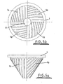
- the conical outer surface of the stator 1 is provided with an arrangement of grooves 1a a (best seen in Figures 5a and 5b ).
- the stator has a double-wall structure defining an internal coolant channel 1b.
- the lower mixing member 2 is a conically concave rotor mounted for rotation about its central axis on an annular slew-ring bearing 5 supported by the lower section of the support frame 3.
- the rotor 2 has an arrangement of grooves 2a formed on its inner surface which in use co-operate with the grooves la formed on the stator as will be described further below.
- the rotor2 is a double-wall structure defining an internal coolant channel 2b which receives coolant via a rotary union 2c.
- the rotor 2 is driven by a suitable motor (not shown) via a gear box 6 and gear shaft 7 provided with a pinion gear 8 which engages an annular gear wheel 9 mounted around the outer circumference of the rotor 2.
- Corresponding apertures 10 and 11 are formed at the apex of both the rotor 2 and stator 1 respectively which align with one another along the axis of rotation of the rotor 2.
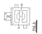
- a plug 12 provided for selectively plugging/unplugging the apertures 10 and 11 is rotatably mounted on a spindle 13, on bearings 14, which projects downwardly from a hydraulic cylinder 15 which is supported above the stator 1 on a cross member 3c of the upper section of the support frame 3.
- the plug 12 is generally cylindrical and has an outer surface which corresponds to the contours of the inner surfaces of the apertures 10 and 11. In use a lower portion of the plug 12 engages the rotor 2 within the aperture 10 so that the plug 12 rotates with the rotor 2.
- Guide rods 16 are provided to prevent the cylinder 15 rotating with the plug 12.
- grooves 1a and 2a formed in the opposing surfaces of the stator 1 and rotor 2 respectively are best seen from Figures 5 and 6 .
- the pattern of grooves is essentially the same on each of the rotor and stator.
- the grooved surface is divided into four sectors (quadrants) by imaginary radial lines projected on to the surface and extending from the axis to the outer periphery of the respective member.
- eight grooves 1a/2a extend from spaced apart locations along one of the radial lines defining that quadrant to similarly spaced apart locations at the outer periphery of the rotor/stator.
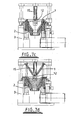
- each quadrant is generally parallel to one another and to a radial line projected on to the surface of rotor/stator. Since all of the grooves extend to the outer periphery of the surface of the rotor/stator (i.e.. the maximum diameter portion of the conical members) but not all of the grooves extend to the centre (apex), the number of grooves defined in the surface effectively increases with the diameter of the stator/rotor. Operation of the mixer will now be described with particular reference to Figures 7a to 7d .
- stator 1 To load material into the mixer, the stator 1 is raised by the hydraulic rams 4 whilst the plug 12 is held in a lowered position in engagement with the aperture 10 in the rotor 2, as illustrated in Figure 7a .
- This enables material to be introduced directly into the interior of the conically concave rotor 2.
- the stator 1 is then lowered so that it nests within the rotor 2 and the upper portion of the plug 12 is received within the aperture 11.
- An appropriate gap is left between the grooved surfaces of the rotor 2 and stator 1 to define the mixing chamber.
- the rotor 2 is then rotated to perform a mixing operation.
- the mixing mechanism is the same asthatdescribed in relation to the original mixer geometry proposed by William Watson as disclosed in UK patent number 2,300,129 mentioned above.
- the grooves 1a in the stator will align with the grooves 2a in the rotor so that material present in the mixing chamber is squeezed into the opposing grooves.
- the rotor 2 and stator then rotate relative to one another the grooves 1a and 2a are brought out of register with one another so that there is a progressive transfer of the material from the grooves into the smaller spaces defined between the lands defined between the grooves of one of the rotor and stator and the opposing lands defined between the grooves of the other of the rotor stator.
- the material is thus extended and sheared which induces the mechanochemical reactions.
- a significant advantage in the mixing mechanism provided by the present invention is that by relating the number of grooves available for mixing material to the radius of the rotor/stator, so that the number of grooves increases with increasing distance from the axis of rotation, it is possible to normalise the shear, extension and scissioning actions so that material at all positions within the chamber is subjected to substantially the same mixing actions. This enables the mixing of material to be kept substantially uniform throughout the mixing chamber as the size of the mixer is scaled up.
- the plug 12 is raised whilst the stator 1 is maintained in its lowered position as shown in Figure 7c , and the rotor 2 is further rotated to pump the mixed material for discharge through the aperture 10 at the apex of the rotor 2.
- the stator 1 is then raised as shown in Figure 7d so that any residual material present can be manually evacuated.
- the plug 12 can then be lowered once again into the position shown in Figure 7a for a subsequent mixing operation.
- the maximum diameter of the mixing members can be minimised in relation to the required mixer volume, surface area and surface speed.
- a relatively large mixer can be provided without the problems associated with over stressing material towards the periphery of the mixing members due to high rotational speeds.
- the torque and thus power requirements to rotate the rotor are reduced in comparison to a planar geometry of similar surface area/volume. Large volumes of material can therefore be mixed in a relatively compact mixer without the need to provide disadvantageously deep grooves.
- the conical geometry is also useful in retaining liquid within the mixer which aids effective distributive mixing.
- gas retention within the cone can provide effective mixing within alternative (e.g. non-oxygenated) environments.
- the exact pattern of grooves could be varied significantly.
- a relatively simple modification of the groove arrangement described above would be to divide the surface into more than four sectors, each sector having a similar arrangement of grooves to those provided in the quadrants of the embodiment described above.
- the feature which provides uniform or substantially uniform mixing across the whole mixing chamber is the provision of an increasing number of grooves with distance from the axis of rotation. For instance it is not necessary for all grooves to extend to the outer peripheral edge of the rotor/stator, nor is it necessary for the pattern of grooves to be identical on both the rotor and stator.
- the configuration of the individual grooves could vary.
- the grooves could be provided with a cross-section which increases with radius to enhance the distributive mixing.
- the mixing surfaces may be provided with protuberances such as raised edges rather than grooves but which may be similarly patterned to provide the required mixing actions and propulsion of material towards or away from the axis of rotation.
- Embodiments of the invention may include a combination of both grooves (or other indentations) and such protuberances.
- mixers embodying certain selected aspects of the present invention include mixers having substantially the same geometry as disclosed in British patent 2,300,129 but with a removable central plug and/or a conical geometry.
Landscapes
- Engineering & Computer Science (AREA)
- Mechanical Engineering (AREA)
- Chemical & Material Sciences (AREA)
- Chemical Kinetics & Catalysis (AREA)
- Food Science & Technology (AREA)
- Environmental & Geological Engineering (AREA)
- Mixers Of The Rotary Stirring Type (AREA)
- Processing And Handling Of Plastics And Other Materials For Molding In General (AREA)
- Mixers With Rotating Receptacles And Mixers With Vibration Mechanisms (AREA)
- Accessories For Mixers (AREA)
- Led Devices (AREA)
- Processing Of Solid Wastes (AREA)
Claims (31)
- Chargenmischvorrichtung, die aufweist:ein erstes und ein zweites entgegengesetztes Mischelement (1, 2), die relativ zueinander um eine Achse drehbar sind;wobei das erste und das zweite Mischelement (1, 2) Planfläche aufweisen, die sich von der Achse weg erstrecken, und die eine Mischkammer dazwischen definieren;Mittel für die Rotation von mindestens einem der Mischelemente (1, 2), um eine relative Rotation zwischen dem ersten und dem zweiten Mischelement (1, 2) in einer ersten Rotationsrichtung zu bewirken;eine Anordnung von Mischausbildungen (1a, 2a) auf mindestens einer der Flächen, die in Wechselwirkung stehen, um Material innerhalb der Mischkammer zu mischen;wobei die Anzahl der Mischausbildungen (1a, 2a) auf mindestens einer der Flächen mit dem radialen Abstand von der Achse größer wird; unddadurch gekennzeichnet, daß mindestens einige der Mischausbildungen (1a, 2a) auf mindestens einer der Flächen relativ zur ersten Rotationsrichtung nach vorn abgelenkt werden, um einen nutzbaren Antrieb des Materials innerhalb der Mischkammer in Richtung der Achse bereitzustellen, während das erste und das zweite Element (1, 2) in der ersten Rotationsrichtung relativ gedreht werden.
- Chargenmischvorrichtung nach Anspruch 1, bei der ein axialer Abschnitt (12) von mindestens einem des ersten und des zweiten Mischelementes (1,2) entfernbar ist, um ein Entleeren des Materials aus der Mischkammer durch eine relative Rotation des ersten und des zweiten Mischelemente (1, 2) in der ersten Rotationsrichtung zu gestatten.
- Chargenmischvorrichtung nach Anspruch 1 oder Anspruch 2, bei der die Mischausbildungen (1a, 2a) Vertiefungen sind.
- Chargenmischvorrichtung nach Anspruch 3, bei der die Vertiefungen (1a, 2a) Rillen sind.
- Chargenmischvorrichtung nach Anspruch 4, bei der die Rillen (1a, 2a) eine Querschnittsfläche definieren, die mit radialem Abstand von der Achse größer wird.
- Chargenmischvorrichtung nach einem der vorhergehenden Ansprüche, die Mischausbildungen aufweist, die aus der jeweiligen Fläche vorstehen
- Chargenmischvorrichtung nach Anspruch 6, bei der die vorstehenden Mischausbildungen erhabene Ränder sind.
- Chargenmischvorrichtung nach einem der vorhergehenden Ansprüche, bei der mindestens einige der Mischausbildungen (1a, 2a) auf beiden Flächen relativ zur ersten Rotationsrichtung nach vorn abgelenkt werden.
- Chargenmischvorrichtung nach einem der vorhergehenden Ansprüche, bei der eine jede Mischausbildung (1a, 2a) auf der mindestens einen Fläche ein radial inneres Ende und ein radial äußeres Ende relativ zur Achse aufweist, wobei die inneren Enden einiger der Mischungausbildungen auf jeder Fläche weiter weg von der Achse sind als andere Mischausbildungen auf der gleichen Fläche.
- Chargenmischvorrichtung nach Anspruch 9, bei der die Anzahl der Mischausbildungen (1a, 2a) auf einer jeweiligen Fläche, die innere Enden relativ entfernt von der Achse aufweist, größer ist als die Anzahl der Misch.ausbildungen auf der gleichen Fläche, die innere Enden relativ nahe zur Achse aufweisen,
- Chargenmischvorrichtung nach Anspruch 9 oder Anspruch 10, bei der das äußere Ende einer jeden Mischausbildung (1a, 2a) am radial äußeren Umfang der jeweiligen Fläche endet.
- Chargenmischvorrichtung nach einem der Ansprüche 9 bis 11, bei der die mindestens eine Fläche in zwei oder mehr Sektoren unterteilt ist, wobei jeder Sektor eine Anordnung von im Wesentlichen parallelen Mischausbildungen (1a, 2a.) aufweist, wobei die Mischausbildungen eines Sektors nicht parallel zu den Mischausbildungen von mindestens einem anderen Sektor sind.
- Chargenmischvrrichtung nach Anspruch 12, bei der die Mischausbildungen (1a, 2a) innerhalb eines speziellen Sektors im Wesentlichen parallel zu einer radialen Linie sind, die auf die jeweilige Fläche projiziert wird.
- Chargenmischvorrichtung nach einem der vorhergehenden Ansprüche, bei der die mindestens eine Fläche in radial innere und äußere Bereiche unterteilt ist, wobei jeder Bereich Mischausbildungen definiert, die innerhalb jenes Bereiches beginnen und enden, wobei die radial äußeren Bereiche mehr Mischausbildungen aufweisen als die radial inneren Bereiche.
- Chargenmischvorridiuang nach einem der Ansprüche 1 bis 8, bei der alle Mischausbildungen auf der mindestens einen Fläche im Wesentlichen parallel zueinander und parallel zu einer radialen Linie sind, die auf die Fläche projiziert wird.
- Chargenmischvorrichtung nach einem der vorhergehenden Ansprüche, bei der beide der Flächen Mischausbildungen (1a, 2a) aufweisen, deren Anzahl mit dem Abstand von der Achse größer wird.
- Chargenmischvorrichtung nach einem der vorhergehenden Ansprüche, bei der die Fläche des ersten Mischelementes (2) konkav und die Fläche des zweiten Mischelementes (1) konvex ist.
- Chargenmischvorrichtung nach Anspruch 17, bei der die Flächen des ersten und des zweiten Mischelementes (1, 2) kegelförmig oder kegelstumpfförmig sind und sich in Richtung der Achse verjüngen.
- Chargenmischvorrichtung nach einem der Ansprüche 1 bis 16, bei der die Flächen der ersten und der zweiten Mischelemente im Wesentlichen eben sind.
- Chargenmischvorrichtung nach Anspruch 2 oder einem davon abhängigen Anspruch, bei der der entfernbare Abschnitt des oder eines jeden Mischelementes einen Stopfen (12) aufweist, der in eine jeweiligen Öffnung (10, 11) in dem oder jedem Mischelement eingesetzt werden kann.
- Chargenmischvorrichtung nach Anspruch 20, bei der ein jedes des ersten und des zweiten Elementes (1, 2) mit einer Öffnung (10, 11) in seiner Mitte versehen ist und ein einzelner Stopfen (12) für das Verstopfen beider Öffnungen (10, 11) vorhanden ist.
- Chargenmischvorrichtung nach Anspruch 21, bei der das erste und das zweite Mischelement (1, 2) von einem Halterahmen (3) getragen werden, wobei das zweite Element (1) über dem ersten Element (2) montiert ist, und wobei der Stopfen (12) auf einem beweglichen Element (13) getragen wird, das sich über dem zweiten Mischelement (1) für ein Einsetzen in und ein Entfernen aus den Öffnungen (10, 11) in den Mischelementen (1, 2) erstreckt.
- Chargenmischvorrichtung nach Anspruch 22, bei der Mittel (4) für das Anheben des zweiten Elementes (1) vorhanden sind, während der Stopfen (12) in Eingriff mit dem ersten Mischelement (2) gehalten wird, um das Einfüllen des zu mischendes Materials in die Mischkammer zu erleichtern.
- Chargenmischvorrichtung nach einem der Ansprüche 20 bis 23, bei der nur eines des ersten und des zweiten Mischelementes (1, 2) drehbar ist, und bei der der Stopfen (12) am beweglichen Element drehbar montiert und so angepasst ist, daß er mit dem drehbaren Mischelement (2) für eine Drehung damit in Eingriff kommt.
- Chargenmischvorrichtung nach Anspruch 2 oder einem davon abhängigen Anspruch, bei der der entfernbar Abschnitt (12) entfernbar ist, während das erste und das zweite Mischelement (1, 2) in einer Richtung relativ gedreht werden, um Material aus der Mischkammer durch eine Öffnung (10) herauszupumpen, die durch Entfernen des entfernbaren Abschnittes offen gelassen wird.
- Chargenmischvorrichtung nach Anspruch 25, bei der Mittel (4) für das Anheben des zweiten Mischelementes (1) vorhanden sind, während der entfernbare Abschnitt (12) außer Eingriff mit dem ersten Mischelement (2) gehalte wird, um das manuelle Entfernen des gemischten Materials zu erleichtern.
- Chargenmischvorrichtung nach einem der Ansprüche 1 bis 23, bei der beide des ersten und des zweiten Mischelementes (1, 2) gegenläufig drehbar sind.
- Chargenmischvorrichtung nach einem der vorhergehenden Ansprüche, bei der Mittel für die selektive relative Rotation des ersten und des zweiten Mischelementes (1, 2) in einer zweiten Rotationsrichtung entgegengesetzt der ersten Rotationsrichtung vorhanden sind, um die Richtung des Antriebes des Materials innerhalb der Mischkammer weg von der Achse umzukehren.
- Verfahren zum Mischen eines Materials in einer Chargenmischvorrichtung, die eine Mischkammer aufweist, die zwischen Planfläche des ersten und des zweiten entgegengesetzten Mischelementes definiert wird, die relativ zueinander um eine Achse drehbar sind, wobei die Planfläche von mindestens dem ersten Mischelement eine Anordnung von Mischausbildungen aufweist, die in Wechselwirkung mit der Planfläche des zweiten Mischelementes stehen, um zu mischen und einen nutzbaren Antrieb des Materials innerhalb der Mischkammer zu bewirken, während das erste und das zweite Mischelement relativ gedreht werden, wobei die Anzahl der Mischausbildungen auf mindestens einer der Flächen mit dem radialen Abstand von der Achse größer wird, wobei mindestens einige der Mischausbildungen relativ zu einer ersten Richtung der Rotation nach vorn abgelenkt werden, um das Material innerhalb der Mischkammer in der Richtung der Achse in Abhängigkeit von der Richtung der relativen Rotation des ersten und des zweiten Mischelementes anzutreiben, wobei das Verfahren das relative Rotieren des ersten und des zweiten Mischelementes in einer Richtung aufweist, so daß die Mischausbildungen in Wechselwirkung stehen, um das Material in Richtung der Achse anzutreiben.
- Verfahren nach Anspruch 29, bei dem ein axialer Abschnitt von mindestens einem des ersten und des zweiten Mischelementes entfernbar ist, und bei dem das Verfahren das Entleeren des gemischten Materials aus dem Mischer durch Entfernen des axialen Abschnittes und relatives Rotieren des ersten und des zweiten Elementes umfaßt, so das das gemischte Material durch eine Öffnung entleert wird, die durch den entfernten axialen Abschnitt gelassen wird.
- Verfahren nach Anspruch 29 oder 30, das das relative Rotieren des ersten und des zweiten Mischelementes in einer Richtung entgegengesetzt der ersten Richtung aufweist, um einen nutzbaren Antrieb des Materials weg von der Achse zu bewirken.
Applications Claiming Priority (3)
| Application Number | Priority Date | Filing Date | Title |
|---|---|---|---|
| GB0202065A GB0202065D0 (en) | 2002-01-30 | 2002-01-30 | Mixing |
| GB0202065 | 2002-01-30 | ||
| PCT/GB2002/005586 WO2003064129A1 (en) | 2002-01-30 | 2002-12-09 | Mixer and method of mixing |
Publications (3)
| Publication Number | Publication Date |
|---|---|
| EP1472061A1 EP1472061A1 (de) | 2004-11-03 |
| EP1472061B1 EP1472061B1 (de) | 2007-11-07 |
| EP1472061B3 true EP1472061B3 (de) | 2010-06-30 |
Family
ID=9929992
Family Applications (1)
| Application Number | Title | Priority Date | Filing Date |
|---|---|---|---|
| EP20020788090 Expired - Lifetime EP1472061B3 (de) | 2002-01-30 | 2002-12-09 | Mischer und mischverfahren |
Country Status (9)
| Country | Link |
|---|---|
| US (1) | US7461970B2 (de) |
| EP (1) | EP1472061B3 (de) |
| JP (2) | JP4919582B2 (de) |
| CN (1) | CN100430196C (de) |
| AT (1) | ATE377495T1 (de) |
| DE (1) | DE60223411T3 (de) |
| ES (1) | ES2299615T7 (de) |
| GB (1) | GB0202065D0 (de) |
| WO (1) | WO2003064129A1 (de) |
Families Citing this family (35)
| Publication number | Priority date | Publication date | Assignee | Title |
|---|---|---|---|---|
| DE102006043581B4 (de) * | 2006-09-12 | 2011-11-03 | Artur Wiegand | Verfahren und Vorrichtung zur Herstellung einer Hartmetall- oder Cermetmischung |
| US8034972B2 (en) * | 2007-06-27 | 2011-10-11 | H R D Corporation | System and process for production of toluene diisocyanate |
| US7842184B2 (en) * | 2007-06-27 | 2010-11-30 | H R D Corporation | Process for water treatment using high shear device |
| US8304584B2 (en) | 2007-06-27 | 2012-11-06 | H R D Corporation | Method of making alkylene glycols |
| US7652174B2 (en) * | 2007-06-27 | 2010-01-26 | H R D Corporation | High shear process for the production of chloral |
| US8034970B2 (en) * | 2007-06-27 | 2011-10-11 | H R D Corporation | Method of making phthalic acid diesters |
| US7482497B2 (en) * | 2007-06-27 | 2009-01-27 | H R D Corporation | Method of making alcohols |
| US7482496B2 (en) | 2007-06-27 | 2009-01-27 | H R D Corporation | Method for making chlorohydrins |
| US7491856B2 (en) * | 2007-06-27 | 2009-02-17 | H R D Corporation | Method of making alkylene glycols |
| US7479576B1 (en) * | 2007-06-27 | 2009-01-20 | H R D Corporation | Method of hydrogenating aldehydes and ketones |
| US20090005619A1 (en) * | 2007-06-27 | 2009-01-01 | H R D Corporation | High shear process for the production of chlorobenzene |
| PL2536489T3 (pl) * | 2010-02-16 | 2014-08-29 | Spcm Sa | Udoskonalone urządzenie do dyspersji polimeru rozpuszczalnego w wodzie |
| JP5794564B2 (ja) * | 2011-05-23 | 2015-10-14 | 株式会社エディプラス | 攪拌装置 |
| EP2755749B1 (de) | 2011-09-16 | 2015-09-30 | Unilever N.V. | Mischvorrichtung sowie verfahren zur herstellung einer essbaren dispersion in solch einer vorrichtung |
| MX338696B (es) * | 2011-11-25 | 2016-04-28 | Rep Internat | Aparato para el procesamiento de material de desecho elastomerico termoestable reticulado. |
| US8673989B2 (en) | 2011-11-25 | 2014-03-18 | New Rubber Technologies Holdings, Inc. | Method of devulcanizing a cross-linked elastomeric material |
| CN102580600A (zh) * | 2012-02-13 | 2012-07-18 | 湖南宁乡吉唯信金属粉体有限公司 | 一种粉末混料机 |
| US9447259B2 (en) | 2012-09-28 | 2016-09-20 | Applied Nanostructured Solutions, Llc | Composite materials formed by shear mixing of carbon nanostructures and related methods |
| US9327969B2 (en) | 2012-10-04 | 2016-05-03 | Applied Nanostructured Solutions, Llc | Microwave transmission assemblies fabricated from carbon nanostructure polymer composites |
| US9133031B2 (en) | 2012-10-04 | 2015-09-15 | Applied Nanostructured Solutions, Llc | Carbon nanostructure layers and methods for making the same |
| CN103801209A (zh) * | 2012-11-06 | 2014-05-21 | 深圳市尚水智能设备有限公司 | 高速搅拌装置 |
| US9107292B2 (en) | 2012-12-04 | 2015-08-11 | Applied Nanostructured Solutions, Llc | Carbon nanostructure-coated fibers of low areal weight and methods for producing the same |
| US8960999B1 (en) | 2014-03-28 | 2015-02-24 | Gudpod Holdings, Llc | System for mixing beverages and method of doing the same |
| CN104014397B (zh) * | 2014-06-04 | 2017-02-01 | 隋鑫 | 磨盘式破碎机 |
| US10399322B2 (en) | 2014-06-11 | 2019-09-03 | Applied Nanostructured Solutions, Llc | Three-dimensional printing using carbon nanostructures |
| US9802373B2 (en) | 2014-06-11 | 2017-10-31 | Applied Nanostructured Solutions, Llc | Methods for processing three-dimensional printed objects using microwave radiation |
| JP6565931B2 (ja) * | 2014-11-25 | 2019-08-28 | 新東工業株式会社 | 分散装置及び分散方法 |
| CN107008537B (zh) * | 2017-04-24 | 2019-05-28 | 江山市艺康化学有限公司 | 一种自动化生产设备 |
| CN107041666B (zh) * | 2017-06-21 | 2018-07-13 | 许美凤 | 一种水杯 |
| RU183634U1 (ru) * | 2018-05-16 | 2018-09-28 | Федеральное государственное бюджетное образовательное учреждение высшего образования "Уфимский государственный нефтяной технический университет" | Турбинный дисковый смеситель |
| BR112021023083A2 (pt) * | 2019-05-17 | 2022-01-25 | Nordson Corp | Câmara de mistura de espuma |
| CN112495282B (zh) * | 2020-12-09 | 2024-04-02 | 安徽省天河食品有限责任公司 | 一种月饼加工用馅料混合搅拌装置 |
| CN112892675B (zh) * | 2021-01-14 | 2022-12-13 | 滁州鸿卓建设有限公司 | 一种建筑工程施工用砂石研磨筛分装置 |
| CN112847936B (zh) * | 2021-02-05 | 2022-12-09 | 渤海水产食品(山东)有限公司 | 一种固体废弃物处理用压实装置 |
| CN113856817B (zh) * | 2021-10-13 | 2023-07-28 | 山东北钛河陶瓷有限公司 | 一种远红外负离子日用陶瓷的原料研磨设备及研磨工艺 |
Family Cites Families (36)
| Publication number | Priority date | Publication date | Assignee | Title |
|---|---|---|---|---|
| US3125305A (en) * | 1964-03-17 | Apparatus for treating material | ||
| US198764A (en) * | 1878-01-01 | Improvement in disintegrating or mixing machines | ||
| US515571A (en) * | 1894-02-27 | Better and dropper | ||
| US112080A (en) * | 1871-02-21 | Improvement in grinding-mills | ||
| US443295A (en) * | 1890-12-23 | Grinding-iviill | ||
| US28681A (en) * | 1860-06-12 | Geotding-mill | ||
| US22384A (en) * | 1858-12-21 | Elotjriitg-mill | ||
| US19093A (en) * | 1858-01-12 | Gbindiug-mill | ||
| US1101199A (en) * | 1912-12-28 | 1914-06-23 | Walter F Legg | Batter cup or bucket. |
| US1791169A (en) * | 1928-11-22 | 1931-02-03 | Schuchardt August | Vertical batch mixer |
| US2847195A (en) * | 1953-12-02 | 1958-08-12 | Morris Bean And Company | Apparatus for mixing |
| US2851257A (en) * | 1954-06-15 | 1958-09-09 | Patterson Kelley Co | Mixing machine |
| US2893708A (en) * | 1955-03-17 | 1959-07-07 | Penberthy Electromelt Company | Glass homogenizer |
| GB1258111A (de) * | 1969-01-23 | 1971-12-22 | ||
| GB2142554B (en) * | 1983-06-10 | 1987-10-21 | Joto Chem Co Ltd | Mixing-milling apparatus for plastics and fillers |
| JPS61259742A (ja) * | 1985-05-13 | 1986-11-18 | Joto Kagaku Kogyo Kk | 混合,混練機 |
| JPS6349239A (ja) * | 1986-08-19 | 1988-03-02 | Ebara Corp | 乳化分散機 |
| US4871686A (en) * | 1988-03-28 | 1989-10-03 | Motorola, Inc. | Integrated Schottky diode and transistor |
| US4992683A (en) * | 1989-09-28 | 1991-02-12 | Motorola, Inc. | Load driver with reduced dissipation under reverse-battery conditions |
| US5493283A (en) * | 1990-09-28 | 1996-02-20 | Olivetti Research Limited | Locating and authentication system |
| RU1776196C (ru) * | 1990-11-21 | 1992-11-15 | Ф.М.АбиТаннам | Устройство дл диспергировани смесей |
| JP3006320B2 (ja) * | 1992-10-21 | 2000-02-07 | モトローラ株式会社 | 高効率ドライバ−を有する電圧変換回路 |
| US5411216A (en) | 1992-12-11 | 1995-05-02 | O'keefe; Dennis | Tire shredder and process for shredding tires |
| JPH06304239A (ja) * | 1993-04-27 | 1994-11-01 | Nichiban Co Ltd | 皮膚用粘着テープ |
| DE9410196U1 (de) | 1994-06-27 | 1994-08-11 | Frenkel C-D AG, Vaduz | Mischer für Polymere |
| JP3439860B2 (ja) | 1995-01-24 | 2003-08-25 | 東レ・ダウコーニング・シリコーン株式会社 | オルガノポリシロキサンエマルジョンの連続的製造方法 |
| US5672992A (en) * | 1995-04-11 | 1997-09-30 | International Rectifier Corporation | Charge pump circuit for high side switch |
| JP3665077B2 (ja) | 1995-04-21 | 2005-06-29 | ワトソン ブラウン エイチエスエム リミティド | 混合 |
| GB2300129B (en) * | 1995-04-21 | 1999-06-02 | William Ferguson Watson | Mixing |
| KR0170511B1 (ko) * | 1995-11-09 | 1999-03-30 | 김광호 | 모스 트랜지스터 구동용 차지펌프회로 |
| DE19546848C2 (de) * | 1995-12-15 | 2002-05-02 | Benno Zimmermann | Mischvorrichtung für Flüssigkeiten |
| US5914589A (en) * | 1996-09-04 | 1999-06-22 | Stmicroelectronics, S.R.L. | Voltage boosting circuit for high-potential-side MOS switching transistor |
| FR2760978B1 (fr) * | 1997-03-19 | 1999-05-21 | Rapidex Inc | Melangeur vertical |
| JPH11209477A (ja) * | 1998-01-29 | 1999-08-03 | Arakawa Chem Ind Co Ltd | 水性樹脂エマルションの連続的製造方法及びその装置 |
| US6201717B1 (en) * | 1999-09-04 | 2001-03-13 | Texas Instruments Incorporated | Charge-pump closely coupled to switching converter |
| WO2002038263A1 (en) | 2000-11-10 | 2002-05-16 | Maelstrom Advanced Process Technologies Ltd | Dynamic mixer |
-
2002
- 2002-01-30 GB GB0202065A patent/GB0202065D0/en not_active Ceased
- 2002-12-09 CN CNB028286936A patent/CN100430196C/zh not_active Expired - Lifetime
- 2002-12-09 US US10/503,566 patent/US7461970B2/en not_active Expired - Lifetime
- 2002-12-09 ES ES02788090T patent/ES2299615T7/es active Active
- 2002-12-09 AT AT02788090T patent/ATE377495T1/de active
- 2002-12-09 WO PCT/GB2002/005586 patent/WO2003064129A1/en not_active Ceased
- 2002-12-09 JP JP2003563793A patent/JP4919582B2/ja not_active Expired - Lifetime
- 2002-12-09 DE DE60223411T patent/DE60223411T3/de not_active Expired - Lifetime
- 2002-12-09 EP EP20020788090 patent/EP1472061B3/de not_active Expired - Lifetime
-
2009
- 2009-12-16 JP JP2009284788A patent/JP2010058123A/ja not_active Withdrawn
Also Published As
| Publication number | Publication date |
|---|---|
| ATE377495T1 (de) | 2007-11-15 |
| CN1625461A (zh) | 2005-06-08 |
| DE60223411D1 (de) | 2010-06-17 |
| EP1472061A1 (de) | 2004-11-03 |
| US7461970B2 (en) | 2008-12-09 |
| CN100430196C (zh) | 2008-11-05 |
| US20050169101A1 (en) | 2005-08-04 |
| EP1472061B1 (de) | 2007-11-07 |
| WO2003064129A1 (en) | 2003-08-07 |
| ES2299615T3 (es) | 2008-06-01 |
| JP4919582B2 (ja) | 2012-04-18 |
| JP2005515915A (ja) | 2005-06-02 |
| JP2010058123A (ja) | 2010-03-18 |
| DE60223411T2 (de) | 2008-09-04 |
| ES2299615T7 (es) | 2011-08-01 |
| GB0202065D0 (en) | 2002-03-13 |
| DE60223411T3 (de) | 2011-01-13 |
Similar Documents
| Publication | Publication Date | Title |
|---|---|---|
| EP1472061B1 (de) | Mischer und mischverfahren | |
| EP1846147B1 (de) | Knet- und granuliermaschine | |
| SU1673184A1 (ru) | Роторный смеситель-диспергатор | |
| US5005982A (en) | Material processor | |
| EP0222599A2 (de) | Vorrichtung zur kontinuierlichen Behandlung von viskosem Material | |
| DE19727663B4 (de) | Zerkleinerungsvorrichtung | |
| WO2004078354A1 (ja) | 粉砕機 | |
| CZ299856B6 (cs) | Ctyrkrídlý rotor pro použití ve vnitrním dávkovacím mísicím stroji pro intenzivní mísení | |
| JP3841949B2 (ja) | コロを用いた分散機 | |
| JP4489256B2 (ja) | 粉砕機 | |
| CN102725065B (zh) | 研磨机和研磨方法 | |
| US3251389A (en) | Machine for and method of comminuting a product | |
| US5289981A (en) | Continuous dispersing apparatus | |
| CN220990528U (zh) | 一种混合机的物料对流装置 | |
| CN113727780A (zh) | 超吸收性聚合物水凝胶切碎装置 | |
| JPH0899047A (ja) | 湿式媒体分散装置 | |
| CN111450945B (zh) | 一种用于生产再生混凝土的建筑垃圾浸入式研磨装置 | |
| JP2898605B2 (ja) | 粒子状材料の処理方法 | |
| JPH0620522B2 (ja) | 連続分散機 | |
| JP2000126635A (ja) | 媒体攪拌ミル | |
| JPH0647070B2 (ja) | 連続分散機 | |
| RU2205105C1 (ru) | Экструдер для переработки термопластичных материалов | |
| WO2000073033A2 (en) | Mixing machines | |
| CN221062999U (zh) | 一种搓磨机 | |
| CN2341713Y (zh) | 一种超细粉碎无间隙组合结构 |
Legal Events
| Date | Code | Title | Description |
|---|---|---|---|
| PUAI | Public reference made under article 153(3) epc to a published international application that has entered the european phase |
Free format text: ORIGINAL CODE: 0009012 |
|
| 17P | Request for examination filed |
Effective date: 20040802 |
|
| AK | Designated contracting states |
Kind code of ref document: A1 Designated state(s): AT BE BG CH CY CZ DE DK EE ES FI FR GB GR IE IT LI LU MC NL PT SE SI SK TR |
|
| AX | Request for extension of the european patent |
Extension state: AL LT LV MK RO |
|
| 17Q | First examination report despatched |
Effective date: 20050728 |
|
| 17Q | First examination report despatched |
Effective date: 20050728 |
|
| GRAP | Despatch of communication of intention to grant a patent |
Free format text: ORIGINAL CODE: EPIDOSNIGR1 |
|
| GRAS | Grant fee paid |
Free format text: ORIGINAL CODE: EPIDOSNIGR3 |
|
| GRAA | (expected) grant |
Free format text: ORIGINAL CODE: 0009210 |
|
| AK | Designated contracting states |
Kind code of ref document: B1 Designated state(s): AT BE BG CH CY CZ DE DK EE ES FI FR GB GR IE IT LI LU MC NL PT SE SI SK TR |
|
| REG | Reference to a national code |
Ref country code: GB Ref legal event code: FG4D |
|
| REG | Reference to a national code |
Ref country code: IE Ref legal event code: FG4D |
|
| REG | Reference to a national code |
Ref country code: CH Ref legal event code: EP |
|
| REF | Corresponds to: |
Ref document number: 60223411 Country of ref document: DE Date of ref document: 20071220 Kind code of ref document: P |
|
| PG25 | Lapsed in a contracting state [announced via postgrant information from national office to epo] |
Ref country code: SE Free format text: LAPSE BECAUSE OF FAILURE TO SUBMIT A TRANSLATION OF THE DESCRIPTION OR TO PAY THE FEE WITHIN THE PRESCRIBED TIME-LIMIT Effective date: 20080207 Ref country code: LI Free format text: LAPSE BECAUSE OF FAILURE TO SUBMIT A TRANSLATION OF THE DESCRIPTION OR TO PAY THE FEE WITHIN THE PRESCRIBED TIME-LIMIT Effective date: 20071107 Ref country code: NL Free format text: LAPSE BECAUSE OF FAILURE TO SUBMIT A TRANSLATION OF THE DESCRIPTION OR TO PAY THE FEE WITHIN THE PRESCRIBED TIME-LIMIT Effective date: 20071107 Ref country code: CH Free format text: LAPSE BECAUSE OF FAILURE TO SUBMIT A TRANSLATION OF THE DESCRIPTION OR TO PAY THE FEE WITHIN THE PRESCRIBED TIME-LIMIT Effective date: 20071107 |
|
| NLV1 | Nl: lapsed or annulled due to failure to fulfill the requirements of art. 29p and 29m of the patents act | ||
| PG25 | Lapsed in a contracting state [announced via postgrant information from national office to epo] |
Ref country code: BG Free format text: LAPSE BECAUSE OF FAILURE TO SUBMIT A TRANSLATION OF THE DESCRIPTION OR TO PAY THE FEE WITHIN THE PRESCRIBED TIME-LIMIT Effective date: 20080207 Ref country code: SI Free format text: LAPSE BECAUSE OF FAILURE TO SUBMIT A TRANSLATION OF THE DESCRIPTION OR TO PAY THE FEE WITHIN THE PRESCRIBED TIME-LIMIT Effective date: 20071107 |
|
| REG | Reference to a national code |
Ref country code: CH Ref legal event code: PL |
|
| REG | Reference to a national code |
Ref country code: ES Ref legal event code: FG2A Ref document number: 2299615 Country of ref document: ES Kind code of ref document: T3 |
|
| PG25 | Lapsed in a contracting state [announced via postgrant information from national office to epo] |
Ref country code: DK Free format text: LAPSE BECAUSE OF FAILURE TO SUBMIT A TRANSLATION OF THE DESCRIPTION OR TO PAY THE FEE WITHIN THE PRESCRIBED TIME-LIMIT Effective date: 20071107 Ref country code: MC Free format text: LAPSE BECAUSE OF NON-PAYMENT OF DUE FEES Effective date: 20071231 Ref country code: CZ Free format text: LAPSE BECAUSE OF FAILURE TO SUBMIT A TRANSLATION OF THE DESCRIPTION OR TO PAY THE FEE WITHIN THE PRESCRIBED TIME-LIMIT Effective date: 20071107 |
|
| ET | Fr: translation filed | ||
| PG25 | Lapsed in a contracting state [announced via postgrant information from national office to epo] |
Ref country code: SK Free format text: LAPSE BECAUSE OF FAILURE TO SUBMIT A TRANSLATION OF THE DESCRIPTION OR TO PAY THE FEE WITHIN THE PRESCRIBED TIME-LIMIT Effective date: 20071107 Ref country code: BE Free format text: LAPSE BECAUSE OF FAILURE TO SUBMIT A TRANSLATION OF THE DESCRIPTION OR TO PAY THE FEE WITHIN THE PRESCRIBED TIME-LIMIT Effective date: 20071107 |
|
| PLBE | No opposition filed within time limit |
Free format text: ORIGINAL CODE: 0009261 |
|
| PG25 | Lapsed in a contracting state [announced via postgrant information from national office to epo] |
Ref country code: PT Free format text: LAPSE BECAUSE OF FAILURE TO SUBMIT A TRANSLATION OF THE DESCRIPTION OR TO PAY THE FEE WITHIN THE PRESCRIBED TIME-LIMIT Effective date: 20080407 |
|
| 26N | No opposition filed |
Effective date: 20080808 |
|
| PG25 | Lapsed in a contracting state [announced via postgrant information from national office to epo] |
Ref country code: IE Free format text: LAPSE BECAUSE OF NON-PAYMENT OF DUE FEES Effective date: 20071210 |
|
| PG25 | Lapsed in a contracting state [announced via postgrant information from national office to epo] |
Ref country code: GR Free format text: LAPSE BECAUSE OF FAILURE TO SUBMIT A TRANSLATION OF THE DESCRIPTION OR TO PAY THE FEE WITHIN THE PRESCRIBED TIME-LIMIT Effective date: 20080208 Ref country code: EE Free format text: LAPSE BECAUSE OF FAILURE TO SUBMIT A TRANSLATION OF THE DESCRIPTION OR TO PAY THE FEE WITHIN THE PRESCRIBED TIME-LIMIT Effective date: 20071107 |
|
| PG25 | Lapsed in a contracting state [announced via postgrant information from national office to epo] |
Ref country code: FI Free format text: LAPSE BECAUSE OF FAILURE TO SUBMIT A TRANSLATION OF THE DESCRIPTION OR TO PAY THE FEE WITHIN THE PRESCRIBED TIME-LIMIT Effective date: 20071107 |
|
| PG25 | Lapsed in a contracting state [announced via postgrant information from national office to epo] |
Ref country code: CY Free format text: LAPSE BECAUSE OF FAILURE TO SUBMIT A TRANSLATION OF THE DESCRIPTION OR TO PAY THE FEE WITHIN THE PRESCRIBED TIME-LIMIT Effective date: 20071107 |
|
| PG25 | Lapsed in a contracting state [announced via postgrant information from national office to epo] |
Ref country code: LU Free format text: LAPSE BECAUSE OF NON-PAYMENT OF DUE FEES Effective date: 20071209 |
|
| PG25 | Lapsed in a contracting state [announced via postgrant information from national office to epo] |
Ref country code: TR Free format text: LAPSE BECAUSE OF FAILURE TO SUBMIT A TRANSLATION OF THE DESCRIPTION OR TO PAY THE FEE WITHIN THE PRESCRIBED TIME-LIMIT Effective date: 20071107 |
|
| PLCP | Request for limitation filed |
Free format text: ORIGINAL CODE: EPIDOSNLIM1 |
|
| PLCQ | Request for limitation of patent found admissible |
Free format text: ORIGINAL CODE: 0009231 |
|
| LIM1 | Request for limitation found admissible |
Free format text: SEQUENCE NO: 1; FILED AFTER OPPOSITION PERIOD Filing date: 20091110 |
|
| PLCO | Limitation procedure: reply received to communication from examining division + time limit |
Free format text: ORIGINAL CODE: EPIDOSNLIR3 |
|
| PLCR | Communication despatched that request for limitation of patent was allowed |
Free format text: ORIGINAL CODE: 0009245 |
|
| PLCN | Payment of fee for limitation of patent |
Free format text: ORIGINAL CODE: EPIDOSNRAL3 |
|
| PUAM | (expected) publication of b3 document |
Free format text: ORIGINAL CODE: 0009410 |
|
| STAA | Information on the status of an ep patent application or granted ep patent |
Free format text: STATUS: THE PATENT HAS BEEN LIMITED |
|
| REG | Reference to a national code |
Ref country code: DE Ref legal event code: 8505 |
|
| REG | Reference to a national code |
Ref country code: CH Ref legal event code: AEN Free format text: BESCHRAENKUNGANTRAG GUTGEHEISSEN |
|
| REG | Reference to a national code |
Ref country code: GB Ref legal event code: 732E Free format text: REGISTERED BETWEEN 20140206 AND 20140212 |
|
| REG | Reference to a national code |
Ref country code: FR Ref legal event code: TP Owner name: REP INTERNATIONAL, FR Effective date: 20140130 |
|
| REG | Reference to a national code |
Ref country code: DE Ref legal event code: R082 Ref document number: 60223411 Country of ref document: DE Representative=s name: MARKS & CLERK (LUXEMBOURG) LLP, LU Effective date: 20140206 Ref country code: DE Ref legal event code: R081 Ref document number: 60223411 Country of ref document: DE Owner name: REP INTERNATIONAL, FR Free format text: FORMER OWNER: WATSON BROWN HSM LTD., GLOSSOP, GB Effective date: 20140206 Ref country code: DE Ref legal event code: R081 Ref document number: 60223411 Country of ref document: DE Owner name: REP INTERNATIONAL, FR Free format text: FORMER OWNER: WATSON BROWN HSM LTD., GLOSSOP, DERBYSHIRE, GB Effective date: 20140206 |
|
| REG | Reference to a national code |
Ref country code: ES Ref legal event code: PC2A Owner name: REP INTERNATIONAL Effective date: 20140411 |
|
| REG | Reference to a national code |
Ref country code: FR Ref legal event code: PLFP Year of fee payment: 14 |
|
| REG | Reference to a national code |
Ref country code: FR Ref legal event code: PLFP Year of fee payment: 15 |
|
| REG | Reference to a national code |
Ref country code: FR Ref legal event code: PLFP Year of fee payment: 16 |
|
| REG | Reference to a national code |
Ref country code: FR Ref legal event code: PLFP Year of fee payment: 17 |
|
| PGFP | Annual fee paid to national office [announced via postgrant information from national office to epo] |
Ref country code: IT Payment date: 20201210 Year of fee payment: 19 |
|
| PGFP | Annual fee paid to national office [announced via postgrant information from national office to epo] |
Ref country code: GB Payment date: 20211220 Year of fee payment: 20 Ref country code: FR Payment date: 20211118 Year of fee payment: 20 Ref country code: DE Payment date: 20211210 Year of fee payment: 20 Ref country code: AT Payment date: 20211123 Year of fee payment: 20 |
|
| PGFP | Annual fee paid to national office [announced via postgrant information from national office to epo] |
Ref country code: ES Payment date: 20220104 Year of fee payment: 20 |
|
| REG | Reference to a national code |
Ref country code: DE Ref legal event code: R071 Ref document number: 60223411 Country of ref document: DE |
|
| REG | Reference to a national code |
Ref country code: GB Ref legal event code: PE20 Expiry date: 20221208 |
|
| REG | Reference to a national code |
Ref country code: AT Ref legal event code: MK07 Ref document number: 377495 Country of ref document: AT Kind code of ref document: T Effective date: 20221209 |
|
| PG25 | Lapsed in a contracting state [announced via postgrant information from national office to epo] |
Ref country code: GB Free format text: LAPSE BECAUSE OF EXPIRATION OF PROTECTION Effective date: 20221208 |
|
| REG | Reference to a national code |
Ref country code: ES Ref legal event code: FD2A Effective date: 20230428 |
|
| PG25 | Lapsed in a contracting state [announced via postgrant information from national office to epo] |
Ref country code: IT Free format text: LAPSE BECAUSE OF NON-PAYMENT OF DUE FEES Effective date: 20211231 |
|
| PG25 | Lapsed in a contracting state [announced via postgrant information from national office to epo] |
Ref country code: ES Free format text: LAPSE BECAUSE OF EXPIRATION OF PROTECTION Effective date: 20221210 |