EP1471507A2 - Verfahren zur holographischen Aufzeichnung und Wiedergabe von Daten und Vorrichtung dafür - Google Patents
Verfahren zur holographischen Aufzeichnung und Wiedergabe von Daten und Vorrichtung dafür Download PDFInfo
- Publication number
- EP1471507A2 EP1471507A2 EP20040009587 EP04009587A EP1471507A2 EP 1471507 A2 EP1471507 A2 EP 1471507A2 EP 20040009587 EP20040009587 EP 20040009587 EP 04009587 A EP04009587 A EP 04009587A EP 1471507 A2 EP1471507 A2 EP 1471507A2
- Authority
- EP
- European Patent Office
- Prior art keywords
- servo
- holographic recording
- recording medium
- signal beam
- signal
- Prior art date
- Legal status (The legal status is an assumption and is not a legal conclusion. Google has not performed a legal analysis and makes no representation as to the accuracy of the status listed.)
- Withdrawn
Links
Images


Classifications
-
- G—PHYSICS
- G11—INFORMATION STORAGE
- G11B—INFORMATION STORAGE BASED ON RELATIVE MOVEMENT BETWEEN RECORD CARRIER AND TRANSDUCER
- G11B7/00—Recording or reproducing by optical means, e.g. recording using a thermal beam of optical radiation by modifying optical properties or the physical structure, reproducing using an optical beam at lower power by sensing optical properties; Record carriers therefor
- G11B7/08—Disposition or mounting of heads or light sources relatively to record carriers
- G11B7/09—Disposition or mounting of heads or light sources relatively to record carriers with provision for moving the light beam or focus plane for the purpose of maintaining alignment of the light beam relative to the record carrier during transducing operation, e.g. to compensate for surface irregularities of the latter or for track following
- G11B7/0938—Disposition or mounting of heads or light sources relatively to record carriers with provision for moving the light beam or focus plane for the purpose of maintaining alignment of the light beam relative to the record carrier during transducing operation, e.g. to compensate for surface irregularities of the latter or for track following servo format, e.g. guide tracks, pilot signals
-
- G—PHYSICS
- G11—INFORMATION STORAGE
- G11B—INFORMATION STORAGE BASED ON RELATIVE MOVEMENT BETWEEN RECORD CARRIER AND TRANSDUCER
- G11B7/00—Recording or reproducing by optical means, e.g. recording using a thermal beam of optical radiation by modifying optical properties or the physical structure, reproducing using an optical beam at lower power by sensing optical properties; Record carriers therefor
- G11B7/004—Recording, reproducing or erasing methods; Read, write or erase circuits therefor
- G11B7/0065—Recording, reproducing or erasing by using optical interference patterns, e.g. holograms
-
- G—PHYSICS
- G11—INFORMATION STORAGE
- G11B—INFORMATION STORAGE BASED ON RELATIVE MOVEMENT BETWEEN RECORD CARRIER AND TRANSDUCER
- G11B7/00—Recording or reproducing by optical means, e.g. recording using a thermal beam of optical radiation by modifying optical properties or the physical structure, reproducing using an optical beam at lower power by sensing optical properties; Record carriers therefor
- G11B7/007—Arrangement of the information on the record carrier, e.g. form of tracks, actual track shape, e.g. wobbled, or cross-section, e.g. v-shaped; Sequential information structures, e.g. sectoring or header formats within a track
- G11B7/00772—Arrangement of the information on the record carrier, e.g. form of tracks, actual track shape, e.g. wobbled, or cross-section, e.g. v-shaped; Sequential information structures, e.g. sectoring or header formats within a track on record carriers storing information in the form of optical interference patterns, e.g. holograms
- G11B7/00781—Auxiliary information, e.g. index marks, address marks, pre-pits, gray codes
-
- G—PHYSICS
- G11—INFORMATION STORAGE
- G11B—INFORMATION STORAGE BASED ON RELATIVE MOVEMENT BETWEEN RECORD CARRIER AND TRANSDUCER
- G11B7/00—Recording or reproducing by optical means, e.g. recording using a thermal beam of optical radiation by modifying optical properties or the physical structure, reproducing using an optical beam at lower power by sensing optical properties; Record carriers therefor
- G11B7/08—Disposition or mounting of heads or light sources relatively to record carriers
- G11B7/083—Disposition or mounting of heads or light sources relatively to record carriers relative to record carriers storing information in the form of optical interference patterns, e.g. holograms
-
- G—PHYSICS
- G11—INFORMATION STORAGE
- G11B—INFORMATION STORAGE BASED ON RELATIVE MOVEMENT BETWEEN RECORD CARRIER AND TRANSDUCER
- G11B7/00—Recording or reproducing by optical means, e.g. recording using a thermal beam of optical radiation by modifying optical properties or the physical structure, reproducing using an optical beam at lower power by sensing optical properties; Record carriers therefor
- G11B7/007—Arrangement of the information on the record carrier, e.g. form of tracks, actual track shape, e.g. wobbled, or cross-section, e.g. v-shaped; Sequential information structures, e.g. sectoring or header formats within a track
- G11B7/00745—Sectoring or header formats within a track
Definitions
- the present invention relates to a method for recording and reproducing holographic data and an apparatus therefor, and more particularly, to a method for recording and reproducing holographic data and an apparatus therefor which can prevent noise from being generated in a reproduced beam or a servo beam.
- the holographic method of recording and reproducing information is known as one method for realizing high-density information recording on a recording medium.
- information is recorded by overlapping a signal beam and a reference beam on the holographic recording medium to write the interference fringes formed thereby.
- the information recorded in the recording medium in this manner can be reproduced by irradiating the recording medium with the reference beam to generate a reproduced beam.
- the reference beam projected onto the recording medium is diffracted by the diffraction grating formed by the interference fringes, thereby causing two-dimensional information to appear as reproduced information.
- high speed reproduction can be realized.
- a conventional method for recording and reproducing holographic information it is normal to cause a signal beam and a reference beam to enter a holographic recording medium with a predetermined angle therebetween when information is to be recorded and to spatially separate the reproduction light and the reference beam for reproducing information when information is to be reproduced, thereby preventing the reference beam from entering a light detector for detecting the reproduction light and preventing decrease in the Signal to Noise ratio of reproduced information.
- the recording and reproduction of data and the control of an address servo operation are performed in a time-sharing manner by dividing the reflection surface of a holographic recording medium into a data area and an address servo area, setting the output of a light source to be low when the light projected through an objective lens passes through the address servo area and setting the output of the light source to be high when the light projected through the objective lens passes through the data area.
- a holographic recording and reproducing method for recording data in a holographic recording medium comprising at least a recording layer in which data are to be recorded as phase information of light by projecting a signal beam and a reference beam thereonto and a servo layer disposed on the opposite side of the recording layer as viewed in the direction of signal beam incidence on the holographic recording medium and having regions in which optical modulated patterns are formed by projecting the signal beam and the reference beam onto the holographic recording medium and reproducing holographic data from the holographic recording medium by projecting the reference beam onto the holographic recording medium, the holographic recording and reproducing method comprising steps of setting an optical path of the signal beam so that the signal beam is projected onto other regions of the servo layer than the regions in which the optical modulated patterns are formed, setting an optical path of a servo beam different from that of the signal beam so that the servo beam is projected onto one of the regions of the servo layer in which the optical modulated patterns are
- a holographic recording and reproducing apparatus for recording data in a holographic recording medium comprising at least a recording layer in which data are to be recorded as phase information of light by projecting a signal beam and a reference beam thereonto and a servo layer disposed on the opposite side of the recording layer as viewed in the direction of signal beam incidence on the holographic recording medium and having regions in which optical modulated pattern are formed by projecting the signal beam and the reference beam onto the holographic recording medium and reproducing holographic data from the holographic recording medium by projecting the reference beam onto the holographic recording medium, the holographic recording and reproducing apparatus comprising an objective lens for converging the signal beam, signal beam projecting means for setting an optical path of the signal beam so that the signal beam is projected onto other regions of the servo layer than the regions in which the optical modulated patterns are formed, and servo beam projecting means for setting an optical path of a servo beam different from that of the signal beam so that the
- the present invention it is possible to prevent noise from being generated in a reproduced beam, prevent the control operation from becoming complicated and prevent storage capacity from being reduced.
- the servo beam projecting means comprises beam deflecting means for deflecting the servo beam in a predetermined direction so that the servo beam impinges on the objective lens with an incidence angle different from that of the signal beam.
- the beam deflecting means is constituted as a diffraction grating disposed on the incidence side of the servo beam with respect to the objective lens.
- the beam deflecting means by a simple device and use an n -th order diffracted light passing through the diffraction grating as the actual servo beam. Further, even in the case where the optical path of the servo beam coincides with that of the signal beam, the optical path of the servo beam can be changed midway.
- Figure 1 is a schematic diagram showing the principle of the holographic recording and reproducing of the present invention.
- a servo beam is used in addition to a signal beam and a reference beam and an address detection operation and a servo control operation are conducted using information obtained by projecting the servo beam onto a holographic recording medium.
- a servo beam 10 and a signal beam 12 are converged by a common objective lens (Fourier transform lens) 14 but since the incidence angles of the servo beam 10 and the signal beam 12 to the objective lens 14 are different from each other, the servo beam 10 and the signal beam 12 passing through the objective lens 14 follow different optical paths.
- a common objective lens Finier transform lens
- the servo beam 10 passing through the objective lens 14 is projected onto a region 16 of the holographic recording medium formed with a servo projection 16 while the signal beam 12 passing through the objective lens 14 is projected onto a region 17 of the holographic recording medium formed with no servo projection 16.
- the signal beam 12 passes through a recording layer 18 in the holographic recording medium and an interference pattern is three-dimensionally formed by the signal beam 12 and a reference beam (not shown) at a region through which the signal beam 12 and the reference beam pass.
- the region where the servo projection 16 is formed since the region where the servo projection 16 is formed is not present on the optical path of the signal beam 12, the region where the servo projection 16 is formed does not serve as a noise source generating noise in a reproduced beam (not shown in Figure 1).
- the reproduced beam is a beam obtained by projecting the reference beam onto a region of the recording layer in which an interference pattern is formed and appears on the optical path of the signal beam 12 in both cases when the signal beam 12 and the reference beam are projected with a predetermined angle and when the signal beam 12 and the reference beam are coaxially projected. This means that if the region where the servo projection 16 is formed is not present on the optical path of the signal beam 12, the region where the servo projection 16 is formed is not present on the optical path of the reference beam and noise can be therefore reduced.
- Figure 2 is a schematic diagram showing a holographic recording and reproducing apparatus that is a preferred embodiment of the present invention.
- a holographic recording and reproducing apparatus 200 includes a laser beam source 201 for emitting a laser beam 210 having a wavelength of ⁇ 0 and adapted for recording data or reproducing data, a beam expander 202 for expanding a laser beam 210 emitted from the laser beam source 201, a beam splitter 203 for splitting the expanded laser beam 210 to generate a signal beam 211a and a reference beam 211b, and a Fourier transform lens 204 disposed on the optical path of the reference beam 211b.
- a total reflection mirror 205 for changing the optical path of the signal beam 211a so that the signal beam 211a impinges on a holographic recording medium 220 perpendicularly thereto, a spatial light modulator (SLM) 206 for modulating the signal beam 211a, a Fourier transform lens 207, a reverse Fourier transform lens 208 and a CCD image sensor 209.
- SLM spatial light modulator
- the holographic recording medium 220 is disposed between the Fourier transform lens 207 and the reverse Fourier transform lens 208.
- the optical paths of the signal beam 211a and the reference beam 211b are determined so that the signal beam 211a and the reference beam 211b overlap each other at a predetermined position in the holographic recording medium 220 when data are recorded in the holographic recording medium 220.
- the holographic recording and reproducing apparatus 200 further includes a laser beam source 231 for a servo control operation that generates a laser beam (servo beam) 211c having a wavelength ⁇ 1 different from the wavelength ⁇ 0 of the signal beam 211a and the reference beam 211b, a beam splitter 232, a collimator 233, a dichroic mirror 234, a diffraction grating 235 and a photo-detector 236.
- a laser beam source 231 for a servo control operation that generates a laser beam (servo beam) 211c having a wavelength ⁇ 1 different from the wavelength ⁇ 0 of the signal beam 211a and the reference beam 211b
- a beam splitter 232 for a servo control operation that generates a laser beam (servo beam) 211c having a wavelength ⁇ 1 different from the wavelength ⁇ 0 of the signal beam 211a and the reference beam 211b
- a beam splitter 232 for a servo control
- the wavelength ⁇ 1 of the servo beam 211c is longer than the wavelength ⁇ 0 of the signal beam 211a and the reference beam 211b but since the resolving power is lowered if the wavelength ⁇ 1 of the servo beam 211c is too long, it is necessary to appropriately determine the wavelength ⁇ 1 of the servo beam 211c.
- a transmission-type holographic recording medium 220 is used.
- the holographic recording medium 220 includes a recording layer 221, an intermediate layer 222 and a servo layer 223 laminated in this order.
- Figure 3 is a schematic cross-sectional view showing the structure of the holographic recording medium 220.
- the recording layer 221 shown in Figure 3 is a layer in which data are to be recorded utilizing holography as phase information of light and is formed of a photosensitive material whose optical properties such as a refractive index, a dielectric constant, a reflection coefficient and the like vary in accordance with the intensity of light when the light is reflected thereby.
- a photosensitive material for forming the recording layer 221 a photosensitive material having high sensitivity with respect to the signal beam 211a and the reference beam 211b and low sensitivity with respect to the servo beam 211c is employed. Otherwise, a servo beam 211c having a wavelength ⁇ 1 which does not influence the recording layer 221 is employed.
- Holographic materials usable for forming the recording layer 221 include photopolymer "HRF-600" (Product Name) manufactured by DuPont, photopolymer "ULSH-500” (Product Name) manufactured by Aprilis, Inc. and the like.
- the intermediate layer 222 is a layer formed between the recording layer 221 and the servo layer 223 and is formed of a material having high light transmittance.
- the servo layer 223 is a layer formed with servo pits on the surface on the incidence side of the servo beam 211c.
- the servo layer 223 is constituted so as to allow the signal beam 211a and the reference beam 211b having a wavelength ⁇ 0 to transmit therethrough and reflect at least a part of the servo beam 211c thereby.
- Substantially band-like regions each formed with a servo projection 224 and regions 225 formed with no servo projection 224 are alternately formed on the surface of the servo layer 223.
- the regions of the servo layer 223 each formed with a servo projection 224 serve as servo tracks and the flat regions 225 are formed between neighboring servo tracks.
- the signal beam 211a is projected onto the flat regions 225 and the servo beam 211c is projected onto the servo tracks.
- the region of the recording layer 221 through which the light beam is transmitted is defined as a region of the recording layer 221 through which an amount of light equal to 1/e 2 of the maximum intensity of the light beam passes.
- the laser beam 210 emitted from the laser beam source 201 for recording data or reproducing data passes through the beam expander 202, whereby the beam is expanded in diameter and made a parallel beam, whereafter the laser beam 210 is split by the beam splitter 203 into the signal beam 211a and the reference beam 211b.
- the signal beam 211a enters the spatial light modulator 206 via the total reflection mirror 205.
- the spatial light modulator 206 has a large number of pixels arranged in a matrix and spatially modulates the intensity of the beam by selectively passing or blocking the light beam at each pixel, thereby generating a signal beam 211a carrying information.
- a liquid crystal device for example, is employed as the spatial light modulator 206. Otherwise a DMD (digital micro-mirror device) can be used.
- the data to be recorded are converted into two-dimensional dot matrix components by an encoder (not shown) and input into the spatial light modulator 206.
- the intensity of the signal beam 211a is spatially modulated by selectively passing or blocking the signal beam at each pixel.
- the signal beam 211a passing through the spatial light modulator 206 further passes through the dichroic mirror 234 and impinges on the diffraction grating 235.
- the diffraction grating 235 generates a diffraction beam of the signal beam 211a impinged thereon.
- a direct beam (zero-th order diffracted beam) passing through the diffraction grating 235 is used, i.e., a diffracted beam is not used.
- an interference pattern is also formed by the overlap of the diffracted beam of the signal beam 211a and the reference beam 211b, since this interference pattern constitutes noise with respect to information to be recorded, it is preferable that the diffracted beam of the signal beam 211a be as small as possible and more preferable that no diffracted beam of the signal beam 211a be generated at all.
- the zero-th order diffracted beam of the signal beam 211a (hereinafter sometimes referred to merely as "signal beam") emitted from the diffraction grating 235 passes through the Fourier transform lens 207 and impinges on the holographic recording medium 220.
- the reference beam 211b only passes through the Fourier transform lens 207 and impinges on the holographic recording medium 220.
- the signal beam 211a and the reference beam 211b are projected onto the same position in the holographic recording medium 220, so that the signal beam 211a and the reference beam 211b overlap.
- an interference pattern is formed by interference of the signal beam 211a and the reference beam211b, whereby data are recorded in the holographic recording medium 220 as phase information of light.
- the holographic recording medium 220 is irradiated with only the reference beam 211b.
- the intensity of the reference beam 211b projected onto the recording position in the holographic recording medium 220 is modulated by the interference pattern and a beam carrying information is reproduced.
- the thus reproduced beam which has been diffracted by the interference pattern in the direction of the optical axis of the signal beam 211a, enters the reverse Fourier transform lens 208.
- Reverse Fourier transformation is effected on the reproduced beam by the reverse Fourier transform lens 208, whereby the reproduced beam is transformed into a beam including dot matrix components and made parallel.
- the beam then enters the CCD image sensor 209, which converts the intensity of the beam into electrical digital signals at each pixel thereof.
- the signals are decoded to the original data by a decoder (not shown).
- the servo beam 211c emitted from the laser beam source 231 passes through the beam splitter 232 and the collimator 233, whereby the servo beam 211c is made a parallel beam.
- the servo beam 211c is then reflected by the dichroic mirror 234 and impinges on the diffraction grating 235.
- a primary diffracted beam of the servo beam 211c is used for a servo control operation.
- the primary diffracted beam of the servo beam 211c (hereinafter sometimes referred to merely as "servo beam") emitted from the diffraction grating 235 passes through the Fourier transform lens 207 and is converged by the Fourier transform lens 207 onto the holographic recording medium 220 so as to be focused onto one of the region of the servo layer 223 formed with the servo pits 224 in the holographic recording medium 220.
- the servo beam 211c is deflected by the diffraction grating 235 in this manner.
- the servo beam 211c impinges on the Fourier transform lens 207 at an incidence angle different from that at which the signal beam 211a impinges on the Fourier transform lens 207 and is projected onto the spot position on the servo track different from that of the signal beam 211a.
- the wavelength ⁇ 1 of the servo beam 211c is different from the wavelength ⁇ 0 of the signal beam 211a and the reference beam 211b, it is possible to set a diffracted angle of the servo beam 211c and select the wavelength ⁇ 1 of the servo beam 211c in accordance with the track pitch without being restricted by wavelength conditions for recording data or reproducing data.
- a case where the pitch of the concavo-convex pattern is particularly wide can be dealt with by setting the wavelength ⁇ 1 to be sufficiently longer than the wavelength ⁇ 0.
- the servo beam 211c is reflected by the servo track to be returned along the original optical path as a returning beam and impinges on the photo-detector 236 via the Fourier transform lens 207, the diffraction grating 235, the dichroic mirror 234, the collimator 233 and the beam splitter 232.
- the intensity and intensity distribution of the servo beam 211c are detected by the photo-detector 236.
- the output of the photo-detector 236 is then processed to conduct a focus servo operation and a tracking servo operation and also generate a reference clock signal and, conduct address discrimination.
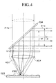
- Figure 4 is a schematic diagram for showing the details of the optical paths of the signal beam 211a and the servo beam 211c.
- the optical axis of the servo beam 211c is tilted by the diffraction grating 235 and then advances to the Fourier transform lens 207.
- the Fourier transform lens 207 converges the servo beam 211c and projects it onto one of the regions of the servo layer 223 formed with the servo projections 224 located at a position different from that of the region through which the signal beam 211a passes.
- the servo beam 211c is then reflected by the region of the servo layer 223 formed with the servo projection 224 and is again impinged on the Fourier transform lens 207. At this time, a part 401 of the servo beam 211c strays outside of the Fourier transform lens 207 so that a loss arises. Most of the servo beam 211c advancing to the Fourier transform lens 207 passes through the diffraction grating 235 and is reflected by the dichroic mirror 234, thereby advancing toward the photo-detector 236. Although the thus returned beam of the servo beam 211c has a beam diameter ⁇ ' smaller than the beam diameter ⁇ of the servo beam 211c projected onto the Fourier transform lens 207, it can be used for a servo control operation.
- the signal beam 211a is projected onto the holographic recording medium 220 so as to pass through a region 225 of the servo layer 223 other than the regions of the servo layer 223 formed with the servo projections 224 and the incidence angle at which the servo beam 211c passing through the Fourier transform lens 207 through which the signal beam 211a also passes is projected onto the holographic recording medium 220 is tilted using the diffraction grating 235 so that the servo beam 211c is projected onto one of the regions of the servo layer 223 in which the servo projections 224 are formed. Therefore, according to this embodiment, it is possible to prevent noise from being generated in the reproduced beam.
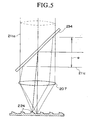
- Figure 5 is a schematic diagram showing a holographic recording and reproducing apparatus that is another preferred embodiment of the present invention.
- the dichroic mirror 234 is used to tilt the optical axis of the servo beam 211c, and a concavo-convex surface of each of the regions where the servo projections 224 are formed obliquely.
- the concavo-convex surface of each of the regions where the servo projections 224 are formed is given an angle so as to be perpendicular to the optical axis of the servo beam 211c.
- the servo beam 211c having a predetermined beam diameter ⁇ is impinged on the dichroic mirror 234, the servo beam 211c is reflected by the dichroic mirror 234. At this time, the optical axis of the servo beam 211c is tilted by a predetermined angle with respect to the optical axis of the signal beam 211a.
- the servo beam 211c advances to the Fourier transform lens 207 and is condensed onto the servo projection 224 located at a different position from that of a region through which the signal beam 211a passes.
- the servo beam 211c reflected by the servo projection 224 returns along the incidence path to pass through the Fourier transform lens 207 be reflected by the dichroic mirror 234 and advance toward the photo-detector 236. Unlike in the previous embodiment, the thus returned servo beam 211c does not stray outside of the Fourier transform lens 207 so that no loss arises. It therefore has the same beam diameter ⁇ as that of the incident servo beam 211c.
- the signal beam 211a is projected onto the holographic recording medium 220 so as to be focused onto the reflection surface thereof. Further, the angle at which the servo beam 211c is impinged on the holographic recording medium 220 is tilted using the dichroic mirror 234 and the concavo-convex surface of each of the regions of the servo layer 223 where the servo projections 224 are formed is correspondingly angled. Therefore, it is possible to prevent noise from being generated in a reproduced beam without using a diffraction grating and further to prevent loss of part of the servo beam 211c during the return of the servo beam 211c along its optical path.
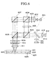
- Figure 6 is a schematic diagram showing a holographic recording and reproducing apparatus that is a further preferred embodiment of the present invention.
- the holographic recording and reproducing apparatus is constituted as a so-called polarization colinear type holographic recording and reproducing apparatus in which a signal beam and a reference beam are projected so as to have a common optical axis.
- a reflection-type holographic recording medium 620 is used in the polarization colinear type holographic recording and reproducing apparatus. Therefore, the surface of a servo layer 623 formed with servo projections constitutes a reflection surface 623r which reflects not only a servo beam having a wavelength of ⁇ 1 but also a signal beam and a reference beam each having a wavelength of ⁇ 0.
- a linear polarized laser beam emitted from a laser beam source 601 for recording data and reproducing data passes through a beam expander 602, whereby it is enlarged in diameter and is then optically rotated by a rotating optical element 603, thereby generating a beam containing an S polarization component and a P polarization component.
- the thus generated beam enters a first polarizing beam splitter 604, thereby dividing it into the S polarization component and the P polarization component.
- the S polarization component is modulated by a spatial light modulator 605 to generate a signal beam having a predetermined pattern.
- the signal beam advances to a second polarizing beam splitter 608 via a first beam splitter 606.
- the P polarization component generated by dividing the above mentioned beam by the first polarizing beam splitter 604 advances to the second polarizing beam splitter 608 via a second beam splitter 607 for use as a reference beam.
- the signal beam and the reference beam advance to a double optically rotating plate 609.
- the double optically rotating plate 609 includes a polarizing plate disposed on the right side of the optical path and a polarizing plate disposed on the left side of the optical path.
- the polarizing plate disposed on the right side is constituted so as to rotate the direction of polarization by -45 degrees and the polarizing plate disposed on the left side is constituted so as to rotate the direction of polarization by +45 degrees.
- the reference beam consisting of the P polarization component and the signal beam consisting of the S polarization component are each optically rotated by the double optically rotating plate 609 in two different directions each corresponding to a region obtained by dividing the beam cross-section in two.
- the signal beam and the reference beam advance to a diffraction grating 610.
- diffracted beams of the signal beam and the reference beam are generated but zero-th order diffracted beams (direct light beams) are used as the signal beam and the reference beam.
- the signal beam and the reference beam advance to the holographic recording medium 620.
- the signal beam which has not yet reached the reflection surface 623r and the reference beam for recording data reflected by the reflection surface 623r interfere with each other to form an interference pattern, thereby recording data in the recording layer 221.
- a laser beam (servo beam) emitted from a laser beam source 612 for servo control and consisting of an S polarization component passes through a collimator 613, a mirror 614, the first beam splitter 606, the second polarizing beam splitter 608 and the double optically rotating plate 609 to impinge on the diffraction grating 610.
- n -th diffracted beams of the servo beam are generated by the diffraction grating 610 but in this embodiment, a primary diffracted beam of the servo beam is used for servo control.
- the primary diffracted beam of the servo beam (hereinafter sometimes referred to merely as "servo beam”) passes through a Fourier transform lens 611 and is converged onto the holographic recording medium 620 so as to be focused on the reflection surface 623r thereof.
- the servo beam is deflected by the diffraction grating 610 in this manner.
- the servo beam impinges on the Fourier transform lens 611 at an incidence angle different from that at which the signal beam impinges on the Fourier transform lens 611 and is projected onto a spot position on the servo track different from that of the signal beam.
- the servo beam is reflected by the servo track to be returned along the original optical path as a returning beam and passes through the Fourier transform lens 611, the diffraction grating 610, the double optically rotating plate 609, the second polarizing beam splitter 608 and the first beam splitter 606 and to impinge on the mirror 614.
- the servo beam is reflected by the mirror 614 and advances to a photo-detector 616 via a condenser lens 615.
- the intensity and the intensity distribution of the servo beam are detected by the photo-detector 616.
- the output of the photo-detector 616 is then processed to conduct a focus servo operation and a tracking servo operation and also generate a reference clock signal and conduct address discrimination.
- the signal beam and the reference beam are coaxially projected onto the holographic recording medium 620
- the signal beam and the reference beam are projected onto the holographic recording medium 620 so as to pass through a region other than the regions formed with the servo projections and the incidence angle at which the servo beam passing through the Fourier transform lens 611 through which the signal beam and the reference beam also pass is projected onto the holographic recording medium 620 is tilted using the diffraction grating 610 so that the servo beam is projected onto one of the region in which the servo projections are formed. Therefore, according to this embodiment, it is possible to prevent noise from being generated in a reproduced beam.
- the part of the servo beam reflected from the holographic recording medium 220, 620 that returns to the Fourier transform lens 207, 611 is used for servo control, it is not absolutely necessary to use the part of the servo beam reflected from the holographic recording medium 220, 620 that returns to the Fourier transform lens 207, 611 for servo control.
- the servo beam In the case where the angle of the servo beam diffracted by the diffraction grating 23 is increased, the servo beam impinges on the reflection surface of the holographic recording medium 220, 620 at a greater angle and the amount of the servo beam reflected by the holographic recording medium 220, 620 and entering the Fourier transform lens 207, 611 as a returned beam becomes small. It therefore becomes possible to effectively detect the servo beam reflected from the holographic recording medium 220, 620 by disposing a photo-detector in a direction in which the servo beam reflected from the holographic recording medium 220, 620 advances.
- the optical axis of the signal beam and the optical axis of the servo beam are made different using the diffraction grating 235, it is not absolutely necessary to use the diffraction grating 235 to make the optical axis of the signal beam and the optical axis of the servo beam different and any means capable of deflecting the servo beam in a predetermined direction suffices.
- the optical axis of the signal beam and the optical axis of the servo beam can be made different using a plane mirror having a discontinuous region along the axis perpendicular to the surface thereof or a concave mirror may be used for making the optical axis of the signal beam and the optical axis of the servo beam different. It is further possible to use a liquid crystal panel capable of deflecting a light beam in pixel units by refraction.
- the descriptions were made as to the case where the servo projections were formed on the servo tracks formed on the servo layer of the holographic recording medium 220, 620.
- the servo projections it is not absolutely necessary for the servo projections to be formed on the servo tracks formed on the servo layer of the holographic recording medium 220, 620 and it is sufficient that an optical pattern capable of modulating a servo beam projected thereonto by varying optical constants of servo tracks, shielding servo tracks with a mask or the like is formed on the servo tracks formed on a servo layer of the holographic recording medium.
- the holographic recording medium is not particularly limited and any of various types of holographic recording media such as card-like, block-like, stick-like or the like can be selected.
- the present invention it is possible to provide a method for recording and reproducing holographic data and an apparatus therefor which can prevent noise from being generated in a reproduced beam, prevent the control operation from becoming complicated and prevent storage capacity from being decreased.
Landscapes
- Optical Recording Or Reproduction (AREA)
- Holo Graphy (AREA)
- Optical Record Carriers And Manufacture Thereof (AREA)
- Optical Head (AREA)
Applications Claiming Priority (2)
| Application Number | Priority Date | Filing Date | Title |
|---|---|---|---|
| JP2003118808A JP3924549B2 (ja) | 2003-04-23 | 2003-04-23 | ホログラム記録再生方法及び装置 |
| JP2003118808 | 2003-04-23 |
Publications (2)
| Publication Number | Publication Date |
|---|---|
| EP1471507A2 true EP1471507A2 (de) | 2004-10-27 |
| EP1471507A3 EP1471507A3 (de) | 2008-05-14 |
Family
ID=32959637
Family Applications (1)
| Application Number | Title | Priority Date | Filing Date |
|---|---|---|---|
| EP04009587A Withdrawn EP1471507A3 (de) | 2003-04-23 | 2004-04-22 | Verfahren zur holographischen Aufzeichnung und Wiedergabe von Daten und Vorrichtung dafür |
Country Status (4)
| Country | Link |
|---|---|
| US (1) | US7372602B2 (de) |
| EP (1) | EP1471507A3 (de) |
| JP (1) | JP3924549B2 (de) |
| CN (1) | CN100403410C (de) |
Cited By (12)
| Publication number | Priority date | Publication date | Assignee | Title |
|---|---|---|---|---|
| EP1691355A1 (de) * | 2005-02-11 | 2006-08-16 | Deutsche Thomson-Brandt Gmbh | Holographisches Plattenmedium mit Servomarken |
| EP1691356A2 (de) | 2005-02-11 | 2006-08-16 | THOMSON Licensing | Holografisches Plattenmedium mit Servomarken |
| EP1697934A1 (de) * | 2003-12-26 | 2006-09-06 | Samsung Electronics Co, Ltd | Hologrammaufzeichnungsmedium und aufzeichnungsvorrichtung und wiedergabevorrichtung dafür |
| EP1826752A1 (de) * | 2006-02-27 | 2007-08-29 | Deutsche Thomson-Brandt Gmbh | Holographisches Speichermedium |
| EP1826753A1 (de) * | 2006-02-27 | 2007-08-29 | Thomson Licensing S.A. | Holographisches Speichermedium |
| WO2007110840A1 (en) * | 2006-03-29 | 2007-10-04 | Koninklijke Philips Electronics N.V. | Setup for storing data in a holographic storage medium |
| KR100767931B1 (ko) | 2006-04-06 | 2007-10-18 | 주식회사 대우일렉트로닉스 | 광정보 처리장치, 광정보 처리방법 그리고 광정보 저장매체 |
| EP1881493A1 (de) * | 2006-07-19 | 2008-01-23 | FUJIFILM Corporation | Informationsaufzeichnungs- und -wiedergabevorrichtung sowie Informationswiedergabeverfahren |
| EP1906391A1 (de) * | 2006-09-28 | 2008-04-02 | Kabushiki Kaisha Toshiba | Optisches Aufzeichnungsmedium mit Holographiefunktion, Verfahren zu seiner Herstellung sowie optische Aufzeichnungs- und Wiedergabevorrichtung |
| EP1965275A1 (de) * | 2005-12-22 | 2008-09-03 | FUJIFILM Corporation | Optisches aufzeichnungsmedium, optische aufzeichnungseinrichtung, optisches aufzeichnungsverfarhen und optisches wiedergabeverfahren |
| WO2009001360A2 (en) * | 2007-06-28 | 2008-12-31 | Mempile Inc. | Optical system for use in recording/reading data in an optical data carrier |
| EP2232491A1 (de) * | 2007-12-28 | 2010-09-29 | Samsung Electronics Co., Ltd. | Vorrichtung zur aufzeichnung und/oder wiedergabe holografischer informationen |
Families Citing this family (33)
| Publication number | Priority date | Publication date | Assignee | Title |
|---|---|---|---|---|
| JP4162518B2 (ja) * | 2003-03-17 | 2008-10-08 | Tdk株式会社 | ホログラム記録再生方法及びホログラム記録媒体 |
| JP4050656B2 (ja) * | 2003-05-09 | 2008-02-20 | 株式会社東芝 | ホログラム記録媒体およびホログラム記録再生方法 |
| JP4267407B2 (ja) * | 2003-08-28 | 2009-05-27 | Tdk株式会社 | ホログラフィック記録媒体、その製造方法、ホログラフィック記録再生システム |
| KR100624275B1 (ko) * | 2004-05-06 | 2006-09-18 | 주식회사 대우일렉트로닉스 | 홀로그래픽 롬 재생기에서의 서보 장치 |
| US20050286386A1 (en) * | 2004-06-29 | 2005-12-29 | Edwards Jathan D | Dichroic coating for holographic data storage media |
| JP2006155831A (ja) * | 2004-11-30 | 2006-06-15 | Fujitsu Ltd | ホログラム記録媒体及びホログラム記録再生装置 |
| EP1701341A1 (de) * | 2005-03-07 | 2006-09-13 | Deutsche Thomson-Brandt Gmbh | Holographishes Aufzeichnungsmedium und Lesekopf für dieses Medium |
| CN1332380C (zh) * | 2005-09-09 | 2007-08-15 | 北京工业大学 | 全息光盘存储器的激光读写镜头 |
| JP4807049B2 (ja) * | 2005-11-21 | 2011-11-02 | 富士ゼロックス株式会社 | ホログラム記録媒体およびこれを用いたホログラム記録方法 |
| JP2007149262A (ja) * | 2005-11-29 | 2007-06-14 | Canon Inc | 光情報再生方法及び光情報記録再生装置 |
| TWI297816B (en) * | 2005-12-21 | 2008-06-11 | Ind Tech Res Inst | System and method for recording and reproducing holographic storage which has tracking servo projection |
| US7576900B2 (en) * | 2005-12-30 | 2009-08-18 | Industrial Technology Research Institute | System and method for holographic storage |
| TWI297817B (en) * | 2005-12-30 | 2008-06-11 | Ind Tech Res Inst | System and mehtod for recording and reproducing holographic storage which has tracking servo projection |
| JP2007264013A (ja) * | 2006-03-27 | 2007-10-11 | Konica Minolta Opto Inc | 光学素子及び双方向光通信モジュール |
| JP4605078B2 (ja) * | 2006-04-05 | 2011-01-05 | 富士ゼロックス株式会社 | 光記録方法、光再生方法、及び光再生装置 |
| WO2008053523A1 (fr) * | 2006-10-31 | 2008-05-08 | Fujitsu Limited | Elément optique d'enregistrement/reproduction d'hologramme et dispositif d'enregistrement/reproduction d'hologramme |
| TWI322990B (en) * | 2006-11-07 | 2010-04-01 | Ind Tech Res Inst | Optical storage system |
| JP4650409B2 (ja) * | 2006-12-22 | 2011-03-16 | 富士ゼロックス株式会社 | ホログラム記録方法、ホログラム記録装置、ホログラム再生方法、ホログラム再生装置、及び光記録媒体 |
| HU0700131D0 (en) * | 2007-02-06 | 2007-05-02 | Bayer Innovation Gmbh | Method of reading a fourier a hologram recorder on a holographic storage medium and a holographic storage system |
| TWI330837B (en) * | 2007-02-14 | 2010-09-21 | Ind Tech Res Inst | System for recording and reproducing holographic storage which has tracking servo projection |
| JPWO2008111210A1 (ja) * | 2007-03-15 | 2010-06-24 | 富士通株式会社 | ホログラム記録装置 |
| TWI335029B (en) * | 2007-04-11 | 2010-12-21 | Ind Tech Res Inst | System for recording and reproducing holographic storage which has tracking servo projection |
| JP2009080906A (ja) | 2007-09-26 | 2009-04-16 | Toshiba Corp | 光情報記録再生装置、回折格子作製装置、光情報記録媒体および位置決め制御方法 |
| WO2009063670A1 (ja) * | 2007-11-14 | 2009-05-22 | Hamamatsu Photonics K.K. | レーザ加工装置およびレーザ加工方法 |
| KR101502622B1 (ko) * | 2007-12-27 | 2015-03-13 | 메이플 비젼 테크놀로지스 인크. | 광정보 처리를 위한 데이터 처리 시스템 및 데이터 처리방법 |
| JP2009187635A (ja) * | 2008-02-07 | 2009-08-20 | Sony Corp | 情報記録媒体初期化装置及び情報記録媒体初期化方法、情報記録装置及び情報記録方法、並びに情報記録媒体 |
| JP4596284B2 (ja) * | 2008-05-26 | 2010-12-08 | ソニー株式会社 | 光ディスク装置及びフォーカス制御方法 |
| JP2012243347A (ja) * | 2011-05-19 | 2012-12-10 | Sony Corp | 記録装置、サーボ制御方法 |
| CN102568798B (zh) * | 2012-02-23 | 2013-11-20 | 深圳顺络电子股份有限公司 | 一种片式共模扼流器排 |
| CN107863116A (zh) * | 2017-12-06 | 2018-03-30 | 苏州盤谷信息光学有限公司 | 一种增加存储容量的光盘记录方法 |
| CN114495991A (zh) * | 2020-11-12 | 2022-05-13 | 华为技术有限公司 | 一种数据读写系统和方法 |
| CN115497515A (zh) * | 2021-06-17 | 2022-12-20 | 广东紫晶信息存储技术股份有限公司 | 一种透射式全息光存储介质和装置以及全息光存储介质双面读写方法 |
| CN115938405A (zh) * | 2021-08-12 | 2023-04-07 | 广东紫晶信息存储技术股份有限公司 | 一种全息光存储光路系统及其菲涅尔透镜或超透镜的设计 |
Citations (4)
| Publication number | Priority date | Publication date | Assignee | Title |
|---|---|---|---|---|
| EP0586185A1 (de) * | 1992-09-02 | 1994-03-09 | Canon Kabushiki Kaisha | Gerät zur Aufnahme und Wiedergabe optischer Daten |
| WO2001080229A2 (en) * | 2000-04-15 | 2001-10-25 | Siros Technologies, Inc. | Optical data storage system with multiple layer media |
| JP2002063733A (ja) * | 2000-08-18 | 2002-02-28 | Nippon Telegr & Teleph Corp <Ntt> | ホログラフィック光記録媒体及び記録再生装置 |
| US20030063342A1 (en) * | 1998-02-27 | 2003-04-03 | Optware Corporation | Apparatus and method for recording optical information, apparatus and method for reproducing optical information, apparatus for recording/reproducing optical information, and optical information recording medium |
Family Cites Families (12)
| Publication number | Priority date | Publication date | Assignee | Title |
|---|---|---|---|---|
| NL7802860A (nl) * | 1978-03-16 | 1979-09-18 | Philips Nv | Registratiedragerlichaam en registratiedrager voor optische informatie en inrichting voor het inschrijven en uitlezen. |
| JP2867950B2 (ja) * | 1996-03-15 | 1999-03-10 | 日本電気株式会社 | 光ディスクの初期化装置 |
| US6738322B2 (en) * | 1999-07-29 | 2004-05-18 | Research Investment Network, Inc. | Optical data storage system with focus and tracking error correction |
| JP3975317B2 (ja) | 2000-04-03 | 2007-09-12 | 富士ゼロックス株式会社 | 光記録方法、光記録装置、光読み取り方法、光読み取り装置 |
| US6540397B2 (en) * | 2000-04-07 | 2003-04-01 | Siro Technologies, Inc. | Optical information storage medium |
| JP2001357542A (ja) | 2000-06-15 | 2001-12-26 | Olympus Optical Co Ltd | 多層光ディスク記録再生装置 |
| DE10134769B4 (de) | 2000-07-13 | 2011-07-28 | Hans Joachim Prof. Dr. 12105 Eichler | Mikroholographische Datenspeicher mit dreidimensionalen Streifengittern |
| JP3655819B2 (ja) | 2000-08-07 | 2005-06-02 | 株式会社オプトウエア | 光情報記録装置および方法、光情報再生装置および方法、ならびに光情報記録再生装置および方法 |
| US6625100B2 (en) | 2001-03-20 | 2003-09-23 | Imation Corp. | Tracking techniques for holographic data storage media |
| US6909529B2 (en) * | 2001-07-31 | 2005-06-21 | Inphase Technologies, Inc. | Method and apparatus for phase correlation holographic drive |
| JP4162518B2 (ja) * | 2003-03-17 | 2008-10-08 | Tdk株式会社 | ホログラム記録再生方法及びホログラム記録媒体 |
| JP2005242304A (ja) * | 2004-01-26 | 2005-09-08 | Pioneer Electronic Corp | ホログラム装置 |
-
2003
- 2003-04-23 JP JP2003118808A patent/JP3924549B2/ja not_active Expired - Lifetime
-
2004
- 2004-04-19 US US10/827,152 patent/US7372602B2/en not_active Expired - Fee Related
- 2004-04-22 EP EP04009587A patent/EP1471507A3/de not_active Withdrawn
- 2004-04-23 CN CNB2004100346843A patent/CN100403410C/zh not_active Expired - Fee Related
Patent Citations (4)
| Publication number | Priority date | Publication date | Assignee | Title |
|---|---|---|---|---|
| EP0586185A1 (de) * | 1992-09-02 | 1994-03-09 | Canon Kabushiki Kaisha | Gerät zur Aufnahme und Wiedergabe optischer Daten |
| US20030063342A1 (en) * | 1998-02-27 | 2003-04-03 | Optware Corporation | Apparatus and method for recording optical information, apparatus and method for reproducing optical information, apparatus for recording/reproducing optical information, and optical information recording medium |
| WO2001080229A2 (en) * | 2000-04-15 | 2001-10-25 | Siros Technologies, Inc. | Optical data storage system with multiple layer media |
| JP2002063733A (ja) * | 2000-08-18 | 2002-02-28 | Nippon Telegr & Teleph Corp <Ntt> | ホログラフィック光記録媒体及び記録再生装置 |
Cited By (20)
| Publication number | Priority date | Publication date | Assignee | Title |
|---|---|---|---|---|
| EP1697934A1 (de) * | 2003-12-26 | 2006-09-06 | Samsung Electronics Co, Ltd | Hologrammaufzeichnungsmedium und aufzeichnungsvorrichtung und wiedergabevorrichtung dafür |
| EP1697934A4 (de) * | 2003-12-26 | 2009-03-25 | Samsung Electronics Co Ltd | Hologrammaufzeichnungsmedium und aufzeichnungsvorrichtung und wiedergabevorrichtung dafür |
| US7440152B2 (en) | 2005-02-11 | 2008-10-21 | Thomson Licensing | Holographic disk medium with servo marks |
| EP1691356A2 (de) | 2005-02-11 | 2006-08-16 | THOMSON Licensing | Holografisches Plattenmedium mit Servomarken |
| EP1691355A1 (de) * | 2005-02-11 | 2006-08-16 | Deutsche Thomson-Brandt Gmbh | Holographisches Plattenmedium mit Servomarken |
| EP1691356A3 (de) * | 2005-02-11 | 2008-12-03 | THOMSON Licensing | Holografisches Plattenmedium mit Servomarken |
| EP1965275A4 (de) * | 2005-12-22 | 2009-09-30 | Fujifilm Corp | Optisches aufzeichnungsmedium, optische aufzeichnungseinrichtung, optisches aufzeichnungsverfarhen und optisches wiedergabeverfahren |
| EP1965275A1 (de) * | 2005-12-22 | 2008-09-03 | FUJIFILM Corporation | Optisches aufzeichnungsmedium, optische aufzeichnungseinrichtung, optisches aufzeichnungsverfarhen und optisches wiedergabeverfahren |
| US7768894B2 (en) | 2006-02-27 | 2010-08-03 | Thomson Licensing | Holographic storage medium |
| EP1826753A1 (de) * | 2006-02-27 | 2007-08-29 | Thomson Licensing S.A. | Holographisches Speichermedium |
| EP1826752A1 (de) * | 2006-02-27 | 2007-08-29 | Deutsche Thomson-Brandt Gmbh | Holographisches Speichermedium |
| WO2007110840A1 (en) * | 2006-03-29 | 2007-10-04 | Koninklijke Philips Electronics N.V. | Setup for storing data in a holographic storage medium |
| KR100767931B1 (ko) | 2006-04-06 | 2007-10-18 | 주식회사 대우일렉트로닉스 | 광정보 처리장치, 광정보 처리방법 그리고 광정보 저장매체 |
| EP1881493A1 (de) * | 2006-07-19 | 2008-01-23 | FUJIFILM Corporation | Informationsaufzeichnungs- und -wiedergabevorrichtung sowie Informationswiedergabeverfahren |
| EP1906391A1 (de) * | 2006-09-28 | 2008-04-02 | Kabushiki Kaisha Toshiba | Optisches Aufzeichnungsmedium mit Holographiefunktion, Verfahren zu seiner Herstellung sowie optische Aufzeichnungs- und Wiedergabevorrichtung |
| WO2009001360A2 (en) * | 2007-06-28 | 2008-12-31 | Mempile Inc. | Optical system for use in recording/reading data in an optical data carrier |
| WO2009001360A3 (en) * | 2007-06-28 | 2009-04-02 | Mempile Inc | Optical system for use in recording/reading data in an optical data carrier |
| EP2232491A1 (de) * | 2007-12-28 | 2010-09-29 | Samsung Electronics Co., Ltd. | Vorrichtung zur aufzeichnung und/oder wiedergabe holografischer informationen |
| EP2232491A4 (de) * | 2007-12-28 | 2011-05-25 | Samsung Electronics Co Ltd | Vorrichtung zur aufzeichnung und/oder wiedergabe holografischer informationen |
| US8018813B2 (en) | 2007-12-28 | 2011-09-13 | Samsung Electronics Co., Ltd. | Holographic information recording and/or reproducing apparatus |
Also Published As
| Publication number | Publication date |
|---|---|
| US20040212859A1 (en) | 2004-10-28 |
| EP1471507A3 (de) | 2008-05-14 |
| JP2004326897A (ja) | 2004-11-18 |
| CN1540458A (zh) | 2004-10-27 |
| US7372602B2 (en) | 2008-05-13 |
| JP3924549B2 (ja) | 2007-06-06 |
| CN100403410C (zh) | 2008-07-16 |
Similar Documents
| Publication | Publication Date | Title |
|---|---|---|
| US7372602B2 (en) | Method for recording and reproducing holographic data and an apparatus therefor | |
| US7002891B2 (en) | Apparatus and method for recording and reproducing information to and from an optical storage medium | |
| US7206108B2 (en) | Method for recording and reproducing holographic data and holographic recording medium | |
| JP3574054B2 (ja) | ホログラフィック光記録媒体、記録装置及び再生装置 | |
| JP4991872B2 (ja) | モノキュラーホログラフィックデータ記憶システムの構成 | |
| US20040165518A1 (en) | Optical information-recording medium, optical information recording apparatus and optical information reproducing apparatus including optical information-recording medium and method for manufacturing polarization changing layer | |
| US20060232841A1 (en) | Holographic recording and reconstructing apparatus and method | |
| US20070153663A1 (en) | Hologram recording/reproducing device and recording/reproducing optical apparatus | |
| JP2006085834A (ja) | 光情報記録装置及び光情報再生装置 | |
| US7012722B2 (en) | Holographic recording apparatus | |
| US8270278B2 (en) | Optical recording apparatus, optical recording method, recording medium, and reproducing method | |
| US7313072B2 (en) | Method for recording and reproducing holographic data and holographic recording medium | |
| WO2006098455A1 (ja) | ホログラム記録再生方法及び装置 | |
| JP4060813B2 (ja) | ホログラフィック記録装置、ホログラフィック再生装置、及びマスク | |
| JP4358602B2 (ja) | 多層ホログラフィック記録再生方法、多層ホログラフィックメモリ再生装置及び多層ホログラフィック記録再生装置 | |
| US20080123506A1 (en) | Optical information recording/reproducing apparatus | |
| JP2005122867A (ja) | 情報光と記録用参照光の光軸が分離しない、2つの焦点を持つ対物レンズによるホログラフィック光情報記録装置 | |
| JP2008027490A (ja) | 情報記録再生装置及び情報再生方法 | |
| JP4631473B2 (ja) | ホログラム記録再生装置およびホログラム記録再生方法 | |
| JP4610976B2 (ja) | ホログラムメモリ媒体および記録装置、再生装置 | |
| JP4590635B2 (ja) | 光情報再生方法、光情報再生装置、光情報記録再生方法及び光情報記録再生装置 | |
| JP2009016008A (ja) | ホログラム記録媒体、トラッキングエラー検出方法、及びホログラム記録再生装置 | |
| JP2008027489A (ja) | 情報記録再生装置及び情報再生方法 | |
| JP2007148112A (ja) | 光情報記録再生装置 | |
| JP2006039160A (ja) | 記録媒体及び記録媒体の製造方法 |
Legal Events
| Date | Code | Title | Description |
|---|---|---|---|
| PUAI | Public reference made under article 153(3) epc to a published international application that has entered the european phase |
Free format text: ORIGINAL CODE: 0009012 |
|
| AK | Designated contracting states |
Kind code of ref document: A2 Designated state(s): AT BE BG CH CY CZ DE DK EE ES FI FR GB GR HU IE IT LI LU MC NL PL PT RO SE SI SK TR |
|
| AX | Request for extension of the european patent |
Extension state: AL HR LT LV MK |
|
| PUAL | Search report despatched |
Free format text: ORIGINAL CODE: 0009013 |
|
| AK | Designated contracting states |
Kind code of ref document: A3 Designated state(s): AT BE BG CH CY CZ DE DK EE ES FI FR GB GR HU IE IT LI LU MC NL PL PT RO SE SI SK TR |
|
| AX | Request for extension of the european patent |
Extension state: AL HR LT LV MK |
|
| RIC1 | Information provided on ipc code assigned before grant |
Ipc: G11B 7/007 20060101ALN20080409BHEP Ipc: G11B 7/08 20060101ALI20080409BHEP Ipc: G11B 7/09 20060101ALI20080409BHEP Ipc: G11B 7/0065 20060101AFI20040726BHEP |
|
| STAA | Information on the status of an ep patent application or granted ep patent |
Free format text: STATUS: THE APPLICATION HAS BEEN WITHDRAWN |
|
| 18W | Application withdrawn |
Effective date: 20080806 |