EP1471313B1 - Gehäuse für die Luftdurchführung - Google Patents
Gehäuse für die Luftdurchführung Download PDFInfo
- Publication number
- EP1471313B1 EP1471313B1 EP04008662.1A EP04008662A EP1471313B1 EP 1471313 B1 EP1471313 B1 EP 1471313B1 EP 04008662 A EP04008662 A EP 04008662A EP 1471313 B1 EP1471313 B1 EP 1471313B1
- Authority
- EP
- European Patent Office
- Prior art keywords
- housing
- arrangement according
- hose
- tube
- arrangement
- Prior art date
- Legal status (The legal status is an assumption and is not a legal conclusion. Google has not performed a legal analysis and makes no representation as to the accuracy of the status listed.)
- Expired - Lifetime
Links
Images


Classifications
-
- F—MECHANICAL ENGINEERING; LIGHTING; HEATING; WEAPONS; BLASTING
- F24—HEATING; RANGES; VENTILATING
- F24F—AIR-CONDITIONING; AIR-HUMIDIFICATION; VENTILATION; USE OF AIR CURRENTS FOR SCREENING
- F24F13/00—Details common to, or for air-conditioning, air-humidification, ventilation or use of air currents for screening
- F24F13/08—Air-flow control members, e.g. louvres, grilles, flaps or guide plates
- F24F13/082—Grilles, registers or guards
- F24F13/085—Grilles, registers or guards including an air filter
Definitions
- the invention relates to an arrangement for the air feedthrough for loading and / or venting a room or areas thereof, with a hose or a pipe and a housing with a connection piece for the arrangement of the fluidically connected to the volume interior of the housing hose or pipe and a room-side, variable-size flow passage with integrated filter holder.
- Housing of the aforementioned type are known per se from the prior art and are used both in a surface-mounted and in a flush-mounted version.
- a generic housing is from the US B1-6,234,893 known. It is used to ventilate residential and / or commercial premises or areas thereof, the air is guided over installed in walls, ceilings or floors sheet metal housing.
- a removable grid is provided, which is arranged by means of screws, pins or the like on the sheet metal housing.
- the grid also serves as a receptacle for a filter insert.
- a disadvantage of the prior art housings is the fact that they can be used exclusively for supply air or exhaust air, ie it is different housing types for use as supply air or exhaust air housing required.
- an assembly of the known housing only with corresponding auxiliary devices possible which makes the installation in particular time consuming and expensive.
- the fly screens used since they are not designed to be closed over their entire area for assembly reasons, so that insects can get into the interior of the housing despite the arrangement of a fly screen.
- Another disadvantage is that the known from the prior art housing are additionally reinforced form depending on the purpose. For example, housings that are cast in a concrete wall to reinforce by means of additional support elements, so that the housing is not pressed due to the applied concrete masses.
- an arrangement is proposed with the invention, which is characterized in that the hose or pipe is arranged secured in the connection piece, wherein the hose or tube is formed wavy and to secure the hose or pipe within the connecting piece a Securing pin is provided in the form of a bracket, which projects through a wave trough of the wave-shaped hose or tube on the one hand and on the other hand formed in the connection piece recesses.
- the housing of the invention is able to avoid the aforementioned disadvantages all.
- the hose or the tube is arranged secured in the connecting piece of the housing.
- An accidental slipping out of the projecting into the housing interior hose or pipe end can be avoided in an advantageous manner.
- the tube or tube used has corrugated hose or tube walls, which advantageously allows an angled installation of the tube or of the tube.
- a locking pin may be provided in the form of a bracket, the Securing quasi a wave trough of the wave-shaped hose or pipe on the one hand and on the other hand through recesses formed in the connecting piece. In a simple way, such a secure arrangement of the housing-side end of the hose or tube is ensured within the connecting piece.
- the flow passage is formed as a frame part and placed in front of the housing in the viewing direction. It serves to arrange a mounting grid having no mounting openings on the one hand and on the other hand in combination with relatively movable arranged cover elements in the form of sliders an adjustable air flow regulation.
- the arrangement of the flow passage causes an improvement in the static strength of the housing, so that it is also at a sprue the housing in a concrete wall of additional reinforcement, as is the case with known from the prior art housings, not required.
- the housing according to the invention can be used equally well for use as Zu Kunststoffgepatuse as well as an exhaust housing, because it is only necessary for a planned use as exhaust air housing, the flow passage to be provided with a corresponding filter, which is why the flow passage according to the invention has integrated filter holder.
- the housing can be used equally well for use as Zu Kunststoffgepatuse as well as an exhaust housing, because it is only necessary for a planned use as exhaust air housing, the flow passage to be provided with a corresponding filter, which is why the flow passage according to the invention has integrated filter holder.
- the housing according to the invention is formed from a wall surrounding a volume space. This wall is open on the room side and closed in the operating state of the housing in the manner of a lid with the variable-size flow passage. Supply or exhaust air is guided through the flow passage in the interior of the housing or out of this in the room to be vented or vented.
- the housing has a connecting piece for the arrangement of a fluidically connected to the volume interior of the housing in connection hose, tube or the like. For ventilation of a room or areas thereof, therefore, corresponding supply air can be guided via the hose into the housing interior and be introduced from there via the flow passage in the space to be ventilated.
- the exhausted room air is sucked out of the space to be vented, which first passes through the flow passage in the housing interior, from where the then on the fluidically connected hose can be removed.
- a corresponding filter is inserted into the integrally formed on Strömungs tellllange filter receptacle, so that the discharged from the space to be vented air first passes through the filter before it can flow into the housing interior.
- the arrangement of the filter has the advantage that any impurities present in the room air can be filtered out before the absorbed air passes through the housing interior and is discharged through the fluidically connected hose. Unwanted contamination of the housing interior and the exhaust air system can be avoided.
- the flow passage is a frame member having a plurality of openings. Covered these openings are completely with a fly screen, so that insects can be effectively prevented from entering the housing interior.
- the dimensions of the frame element are dimensioned such that it can be inserted into the recess forming the chamber-side opening of the wall of the housing.
- the size of the frame member on the one hand and the size of the recess provided in the wall of the housing on the other hand matched to one another such that the frame member can be inserted into the recess substantially gap-free. This advantageously achieves edge-side sealing of the frame element relative to the housing, so that the air flowing through the flow passage passes exclusively through the openings provided in the flow passage into the interior of the housing or out of it.
- the flow passage on cover elements which are arranged to be at least partially covering the openings provided in the flow passage slidably.
- These cover elements are preferably designed as a slide and serve to regulate the amount of air flowing through the flow passage at a given pressure. In this way, an exact adjustment of the user as desired required air flow circulation can be made.
- the filter receptacle is formed by two webs formed on the flow passage. These webs are preferably along the side of the flow passage forming frame member.
- the height of the webs preferably corresponds to the height of the filter, so that when the filter is inserted, a substantially flat end surface is formed.
- the arrangement of two webs has the advantage that the filter element can be used or replaced in a simple manner. The handling of the housing is thus also conceivable in terms of the arrangement of the filter.
- the housing has at least one mounting bracket.
- This mounting bracket is arranged on the outside of the housing displaceable on this and serves to fix the housing in the installation space.
- the housing has two mounting brackets, which are each arranged on the opposite longitudinal sides of the housing.
- sound insulation elements are provided for sound insulation, which are arranged as sound-absorbing material in the interior of the housing.
- sound insulation can be provided to form the protruding into the interior of the housing end of the air-conducting hose or pipe such that the air flowing in via the tube or the pipe is deflected by 180 ° before it reaches the outlet opening of the housing. This can be achieved, for example, by an end formed in the hose or the pipe pawl or stepped recess.
- a grille is provided, which is placed on the flow passage on the front side.
- the cover grille can be designed both in the form of an overpainted version and in the form of a flush-mounted variant.
- the grille is arranged releasably arranged preferably by means of resilient retaining elements. These resilient retaining elements engage in correspondingly formed receptacles, which are formed on the housing side.
- resilient retaining elements engage in correspondingly formed receptacles, which are formed on the housing side.
- the frame for mounting the flush-mounted grilles are preferably formed with slots so that they can be screwed onto the leg of the mounting bracket and on the other hand so as to rotate or move against both sides of the housing. This ensures that despite a possibly imprecise mounting of the housing, the grid frame can be aligned more precisely in relation to the mounting wall.
- an additional connecting piece for the arrangement of a further tube, pipe or the like is provided.
- the design of a further connecting piece allows the direct connection of the housing to a toilet bowl or urinal.
- the air located in the volume space of a toilet body or a urinal can be aspirated directly in this way via the housing according to the invention.
- mixing of the air originating from a toilet body or a urinal with the rest of the room air can advantageously be avoided, which is advantageous in particular from the point of view of odor nuisance.
- an additional filter holder which serves to receive a further filter, which filters the air coming from the tube arranged in the second connection, before it penetrates into the volume interior of the housing.
- the arrangement of such a filter receptacle is particularly suitable when connecting the housing to a toilet body or urinal.
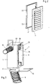
- Fig. 1 shows a perspective view of the housing 1 according to the invention, wherein the individual housing components are shown exploded.
- the housing 1 consists of a surrounding a volume space 2 wall 3. Formed this wall is preferably made of stainless steel.
- the room side, the wall 3 is made open and has a recess 4.
- a flow passage 5, a filter 6 and a cover grille 7 are placed on this recess 4.
- room air can thus reach the volume space 2 enclosed by the housing 1 via the grille 7, the filter 6 and the flow passage 5.
- the flow of air takes place in the opposite direction, ie from the volume space 2 of the housing 1 out the air flows through the flow passage 5, the filter 6 and the grille 7 in the room to be ventilated.
- a connecting piece 8 which serves the arrangement of an air-conveying hose 9.
- the fresh supply air flows through the tube 9 into the volume space 2 of the housing 1 and leaves it through the recess 4, ie flows through the flow passage 5, the filter 6 and the cover 7.
- the spent exhaust air passes through the recess 4 of the housing 1 in the volume space 2, wherein any foreign substances contained in the exhaust air are filtered out via the filter 6, and is then sucked out of the housing interior via the hose 9.
- a securing bracket 10 is provided for secure arrangement of the hose 9 within the connecting piece 8.
- This circlip is introduced into recesses 11 formed on the connection piece, wherein in the completely assembled state it projects through a wave trough of the wave-shaped tube 9. Is achieved by this arrangement a backup of the hose 9 with respect to the connection piece 8, whereby this is fixed in position secure.
- the flow passage 5 has a plurality of passage openings. According to the embodiment according to Fig. 1 are a total of four openings 12 are provided. To regulate the amount of air passing through the passage openings 12 of the flow passage 5 air displaceably arranged cover elements in the form of sliders 13 are provided relative to the flow passage. These slides can be selectively moved to a position desired by the user, whereby this can adjust the size of the total available for the air passages, which at constant pressure for regulating the amount of air passed through the housing leads.
- the in Fig. 1 exemplified flow passage 5 is formed as a frame member and has a total of four openings 12, which are each covered by a fly screen 14. On the longitudinal sides of the frame member, a web 15 is formed in each case. Together, these webs 15 form a flow passage 5 integrally formed filter receptacle, which serves the arrangement of the filter 6.
- the advantage of this embodiment is to be seen in the particularly simple handling, because it is only necessary for an assembly of flow passage 5 and filter 6, the filter 6 between the two arranged on the flow passage 5 webs 15 and the flow passage 5 then together with filter 6 in the recess 4 of the housing 1 to position.
- the filter 6 is used in particular when the housing 1 is used as an exhaust air housing.
- a mounting bracket 16 is arranged on each side of the housing box.
- This mounting bracket is preferably arranged on guided in elongated holes 17 fastening means 18 on the housing 1, so that for the purpose of readjustment, a relative displacement between the housing 1 and mounting bracket 16 can be made.
- this has spring-loaded retaining elements 19.
- these holding elements 19 engage in corresponding recesses 20 formed in the housing interior, which have, for example, the shape of hollow profiled body.
- FIG. 1 illustrated grille 7 is used for over-plaster use.
- the longitudinal slots 22 provided in the lattice frame 21 serve for a possible readjustment of the lattice frame 21 and the louver 7 relative to the housing 1.
- FIG. 3 shows an alternative embodiment of the housing according to the invention. Shown here is a housing arrangement, according to those Fig. 1 corresponds, wherein an additional connecting piece 23 is provided for the arrangement of a further hose 24.
- This type of configuration is used in particular the direct connection of the housing according to the invention to a toilet body or urinal, which advantageously in avoiding mixing with the rest of the room air located in the toilet body or the urinal air can be sucked directly through the housing 1.
- an additional filter holder 25 is provided within the housing 1, which serves to receive a filter 26.
- a partially sectioned side view shows Fig. 4 the embodiment according to Fig. 3 , It can be clearly seen here that the interior of the housing is lined with a sound-absorbing material 27 for sound insulation. In addition, it can be seen that the housing-side end of the tube 9 is provided with a stepped recess 28. This achieves the fact that the air flowing into the interior of the housing through the hose 9 is first deflected by 180 °, before it leaves the volume space 2 via the recess 4, ie the flow passage 5, the filter 6 and the cover grille 7. The advantage of this 180 ° air deflection is the additional noise reduction.
- Fig. 5 schematically shows a double arrangement of the housing according to the invention. Shown are two housing 1, which are connected to each other via a corresponding connecting element 29. To cover both Gezzauseaus traditions 4 either a common or a single cover for each housing may be provided.
- plastic spacer 30 may be arranged on the mounting bracket, as this Fig. 6 can be removed.
Landscapes
- Engineering & Computer Science (AREA)
- Chemical & Material Sciences (AREA)
- Combustion & Propulsion (AREA)
- Mechanical Engineering (AREA)
- General Engineering & Computer Science (AREA)
- Ventilation (AREA)
- Duct Arrangements (AREA)
Priority Applications (1)
| Application Number | Priority Date | Filing Date | Title |
|---|---|---|---|
| PL04008662T PL1471313T3 (pl) | 2003-04-25 | 2004-04-10 | Obudowa do przeprowadzania powietrza |
Applications Claiming Priority (2)
| Application Number | Priority Date | Filing Date | Title |
|---|---|---|---|
| DE20306453U DE20306453U1 (de) | 2003-04-25 | 2003-04-25 | Gehäuse für die Luftdurchführung |
| DE20306453U | 2003-04-25 |
Publications (2)
| Publication Number | Publication Date |
|---|---|
| EP1471313A1 EP1471313A1 (de) | 2004-10-27 |
| EP1471313B1 true EP1471313B1 (de) | 2018-02-07 |
Family
ID=27763146
Family Applications (1)
| Application Number | Title | Priority Date | Filing Date |
|---|---|---|---|
| EP04008662.1A Expired - Lifetime EP1471313B1 (de) | 2003-04-25 | 2004-04-10 | Gehäuse für die Luftdurchführung |
Country Status (4)
| Country | Link |
|---|---|
| EP (1) | EP1471313B1 (pl) |
| DE (1) | DE20306453U1 (pl) |
| ES (1) | ES2666159T3 (pl) |
| PL (1) | PL1471313T3 (pl) |
Families Citing this family (4)
| Publication number | Priority date | Publication date | Assignee | Title |
|---|---|---|---|---|
| DE202005003475U1 (de) * | 2005-03-04 | 2005-05-25 | Zehnder Verkaufs- Und Verwaltungs Ag | Gehäuse für die Luftdurchführung |
| DE202010014480U1 (de) * | 2010-10-19 | 2010-12-23 | Zehnder Verkaufs- Und Verwaltungs Ag | Kupplungsmuffe |
| IT201600078849A1 (it) * | 2016-07-27 | 2018-01-27 | Ideal Clima Srl | Procedimento per realizzare una bocchetta nascosta migliorata per impianti di ventilazione, riscaldamento e climatizzazione, e assieme bocchetta per attuare tale procedimento. |
| EP3536876B1 (de) | 2018-03-08 | 2020-09-30 | Hoval Aktiengesellschaft | Lüftungsgehäuse-schutzabdeckung |
Family Cites Families (8)
| Publication number | Priority date | Publication date | Assignee | Title |
|---|---|---|---|---|
| DE2124440B2 (de) | 1970-05-29 | 1976-11-11 | AB Svenska Fläktfabriken, Nacka (Schweden) | Vorgefertigtes, transportables grossgehaeuse zur aufnahme von lueftungstechnischen aggregaten |
| US4407187A (en) * | 1981-12-15 | 1983-10-04 | Horney Robert W | Air control device |
| DE3532169A1 (de) | 1985-09-10 | 1987-04-16 | Berger Gmbh & Co Gerhard | Filter |
| DE4028899C1 (pl) | 1990-09-12 | 1992-01-09 | Mercedes-Benz Aktiengesellschaft, 7000 Stuttgart, De | |
| US5472380A (en) * | 1994-05-26 | 1995-12-05 | Sarazen, Jr.; Paul M. | Modular forced-air floor register with filter |
| DE19752019A1 (de) | 1997-11-24 | 1999-05-27 | Andreas Geisl | Belüftungsvorrichtung und Belüftungssystem |
| US6234893B1 (en) | 2000-07-01 | 2001-05-22 | Jerry R. Meredith | Vent device for use with medium for altering a condition of air entering an environment |
| BE1014264A3 (nl) * | 2001-06-22 | 2003-07-01 | Oroplastic Nv | Kunststof planchet en werkwijze voor het vervaardigen ervan. |
-
2003
- 2003-04-25 DE DE20306453U patent/DE20306453U1/de not_active Expired - Lifetime
-
2004
- 2004-04-10 EP EP04008662.1A patent/EP1471313B1/de not_active Expired - Lifetime
- 2004-04-10 PL PL04008662T patent/PL1471313T3/pl unknown
- 2004-04-10 ES ES04008662.1T patent/ES2666159T3/es not_active Expired - Lifetime
Non-Patent Citations (1)
| Title |
|---|
| None * |
Also Published As
| Publication number | Publication date |
|---|---|
| PL1471313T3 (pl) | 2018-07-31 |
| DE20306453U1 (de) | 2003-08-14 |
| EP1471313A1 (de) | 2004-10-27 |
| ES2666159T3 (es) | 2018-05-03 |
Similar Documents
| Publication | Publication Date | Title |
|---|---|---|
| DE102004042291B4 (de) | Höhenverstelleinrichtung für eine deckenbefestigte Dunstabzugshaube sowie Dunstabzugshaube | |
| DE102007008019B4 (de) | Luftauslass | |
| DE4312664C1 (de) | Filterlüfter | |
| DE2742734A1 (de) | Axialventilator | |
| EP1471313B1 (de) | Gehäuse für die Luftdurchführung | |
| DE102014016878A1 (de) | Klimaanlage mit Windschild | |
| DE69621058T2 (de) | Filter- und Abzughaube mit Regelung des Luftstromes | |
| DE19752019A1 (de) | Belüftungsvorrichtung und Belüftungssystem | |
| DE2531247A1 (de) | Frischluftschleuse zur belueftung von raeumen | |
| EP3361175B1 (de) | Deckenelement, insbesondere einer kühl- oder heizdecke | |
| DE4232315A1 (de) | Zulufteinrichtung zum Einbau in Außenwänden von Gebäuden und/oder Wohnungen | |
| DE20122340U1 (de) | Dunstabzugshaube | |
| EP1698838B1 (de) | Gehäuse für die Luftdurchführung | |
| EP2708827B1 (de) | Luftaus- oder -einlass und Lüftungssystem hiermit | |
| CH682012A5 (en) | Motor driven bathroom ventilator | |
| EP3124869B1 (de) | Luftauslassgitter, insbesondere für einen ofen | |
| EP0667496B1 (de) | Lüftungskasten | |
| DE102006062986B3 (de) | Sanitäre Auslaufarmatur mit einem Strahlregler | |
| DE10106646C1 (de) | Mauerkasten für Abluft- und Zuluft-Durchleitung durch eine Wand | |
| DE9212993U1 (de) | Zulufteinrichtung zum Einbau in Außenwänden von Gebäuden und/oder Wohnungen | |
| EP0236683B1 (de) | Lufteinlass-, Luftauslass- und/oder Luftverteilervorrichtung, insbesondere Lüftungsvorrichtung für Räume | |
| DE9101692U1 (de) | Lüftungskanalelement zur Einbeziehung in einen Luftkanal | |
| DE202006017606U1 (de) | Türanordnung | |
| DE202026100610U1 (de) | Lüftungsvorrichtung | |
| DE10319007B4 (de) | Anschlußarmatur für die Luftzu- und/oder -abführung eines Raumlüftungsgerätes |
Legal Events
| Date | Code | Title | Description |
|---|---|---|---|
| PUAI | Public reference made under article 153(3) epc to a published international application that has entered the european phase |
Free format text: ORIGINAL CODE: 0009012 |
|
| AK | Designated contracting states |
Kind code of ref document: A1 Designated state(s): AT BE BG CH CY CZ DE DK EE ES FI FR GB GR HU IE IT LI LU MC NL PL PT RO SE SI SK TR |
|
| AX | Request for extension of the european patent |
Extension state: AL HR LT LV MK |
|
| 17P | Request for examination filed |
Effective date: 20041119 |
|
| AKX | Designation fees paid |
Designated state(s): AT BE BG CH CY CZ DE DK EE ES FI FR GB GR HU IE IT LI LU MC NL PL PT RO SE SI SK TR |
|
| 17Q | First examination report despatched |
Effective date: 20090709 |
|
| RAP1 | Party data changed (applicant data changed or rights of an application transferred) |
Owner name: ZEHNDER GROUP INTERNATIONAL AG |
|
| GRAP | Despatch of communication of intention to grant a patent |
Free format text: ORIGINAL CODE: EPIDOSNIGR1 |
|
| STAA | Information on the status of an ep patent application or granted ep patent |
Free format text: STATUS: GRANT OF PATENT IS INTENDED |
|
| INTG | Intention to grant announced |
Effective date: 20170904 |
|
| GRAS | Grant fee paid |
Free format text: ORIGINAL CODE: EPIDOSNIGR3 |
|
| GRAA | (expected) grant |
Free format text: ORIGINAL CODE: 0009210 |
|
| STAA | Information on the status of an ep patent application or granted ep patent |
Free format text: STATUS: THE PATENT HAS BEEN GRANTED |
|
| AK | Designated contracting states |
Kind code of ref document: B1 Designated state(s): AT BE BG CH CY CZ DE DK EE ES FI FR GB GR HU IE IT LI LU MC NL PL PT RO SE SI SK TR |
|
| REG | Reference to a national code |
Ref country code: GB Ref legal event code: FG4D Free format text: NOT ENGLISH |
|
| REG | Reference to a national code |
Ref country code: AT Ref legal event code: REF Ref document number: 968964 Country of ref document: AT Kind code of ref document: T Effective date: 20180215 Ref country code: CH Ref legal event code: EP |
|
| REG | Reference to a national code |
Ref country code: IE Ref legal event code: FG4D Free format text: LANGUAGE OF EP DOCUMENT: GERMAN |
|
| REG | Reference to a national code |
Ref country code: DE Ref legal event code: R096 Ref document number: 502004015643 Country of ref document: DE |
|
| REG | Reference to a national code |
Ref country code: FR Ref legal event code: PLFP Year of fee payment: 15 |
|
| REG | Reference to a national code |
Ref country code: ES Ref legal event code: FG2A Ref document number: 2666159 Country of ref document: ES Kind code of ref document: T3 Effective date: 20180503 |
|
| REG | Reference to a national code |
Ref country code: NL Ref legal event code: FP |
|
| PG25 | Lapsed in a contracting state [announced via postgrant information from national office to epo] |
Ref country code: CY Free format text: LAPSE BECAUSE OF FAILURE TO SUBMIT A TRANSLATION OF THE DESCRIPTION OR TO PAY THE FEE WITHIN THE PRESCRIBED TIME-LIMIT Effective date: 20180207 Ref country code: FI Free format text: LAPSE BECAUSE OF FAILURE TO SUBMIT A TRANSLATION OF THE DESCRIPTION OR TO PAY THE FEE WITHIN THE PRESCRIBED TIME-LIMIT Effective date: 20180207 |
|
| PG25 | Lapsed in a contracting state [announced via postgrant information from national office to epo] |
Ref country code: SE Free format text: LAPSE BECAUSE OF FAILURE TO SUBMIT A TRANSLATION OF THE DESCRIPTION OR TO PAY THE FEE WITHIN THE PRESCRIBED TIME-LIMIT Effective date: 20180207 Ref country code: BG Free format text: LAPSE BECAUSE OF FAILURE TO SUBMIT A TRANSLATION OF THE DESCRIPTION OR TO PAY THE FEE WITHIN THE PRESCRIBED TIME-LIMIT Effective date: 20180507 Ref country code: GR Free format text: LAPSE BECAUSE OF FAILURE TO SUBMIT A TRANSLATION OF THE DESCRIPTION OR TO PAY THE FEE WITHIN THE PRESCRIBED TIME-LIMIT Effective date: 20180508 |
|
| PG25 | Lapsed in a contracting state [announced via postgrant information from national office to epo] |
Ref country code: RO Free format text: LAPSE BECAUSE OF FAILURE TO SUBMIT A TRANSLATION OF THE DESCRIPTION OR TO PAY THE FEE WITHIN THE PRESCRIBED TIME-LIMIT Effective date: 20180207 Ref country code: EE Free format text: LAPSE BECAUSE OF FAILURE TO SUBMIT A TRANSLATION OF THE DESCRIPTION OR TO PAY THE FEE WITHIN THE PRESCRIBED TIME-LIMIT Effective date: 20180207 |
|
| REG | Reference to a national code |
Ref country code: DE Ref legal event code: R097 Ref document number: 502004015643 Country of ref document: DE |
|
| PG25 | Lapsed in a contracting state [announced via postgrant information from national office to epo] |
Ref country code: SK Free format text: LAPSE BECAUSE OF FAILURE TO SUBMIT A TRANSLATION OF THE DESCRIPTION OR TO PAY THE FEE WITHIN THE PRESCRIBED TIME-LIMIT Effective date: 20180207 Ref country code: DK Free format text: LAPSE BECAUSE OF FAILURE TO SUBMIT A TRANSLATION OF THE DESCRIPTION OR TO PAY THE FEE WITHIN THE PRESCRIBED TIME-LIMIT Effective date: 20180207 Ref country code: MC Free format text: LAPSE BECAUSE OF FAILURE TO SUBMIT A TRANSLATION OF THE DESCRIPTION OR TO PAY THE FEE WITHIN THE PRESCRIBED TIME-LIMIT Effective date: 20180207 Ref country code: CZ Free format text: LAPSE BECAUSE OF FAILURE TO SUBMIT A TRANSLATION OF THE DESCRIPTION OR TO PAY THE FEE WITHIN THE PRESCRIBED TIME-LIMIT Effective date: 20180207 |
|
| PLBE | No opposition filed within time limit |
Free format text: ORIGINAL CODE: 0009261 |
|
| STAA | Information on the status of an ep patent application or granted ep patent |
Free format text: STATUS: NO OPPOSITION FILED WITHIN TIME LIMIT |
|
| 26N | No opposition filed |
Effective date: 20181108 |
|
| REG | Reference to a national code |
Ref country code: IE Ref legal event code: MM4A |
|
| PG25 | Lapsed in a contracting state [announced via postgrant information from national office to epo] |
Ref country code: LU Free format text: LAPSE BECAUSE OF NON-PAYMENT OF DUE FEES Effective date: 20180410 |
|
| PG25 | Lapsed in a contracting state [announced via postgrant information from national office to epo] |
Ref country code: SI Free format text: LAPSE BECAUSE OF FAILURE TO SUBMIT A TRANSLATION OF THE DESCRIPTION OR TO PAY THE FEE WITHIN THE PRESCRIBED TIME-LIMIT Effective date: 20180207 |
|
| PG25 | Lapsed in a contracting state [announced via postgrant information from national office to epo] |
Ref country code: IE Free format text: LAPSE BECAUSE OF NON-PAYMENT OF DUE FEES Effective date: 20180410 |
|
| REG | Reference to a national code |
Ref country code: AT Ref legal event code: MM01 Ref document number: 968964 Country of ref document: AT Kind code of ref document: T Effective date: 20180410 |
|
| PG25 | Lapsed in a contracting state [announced via postgrant information from national office to epo] |
Ref country code: AT Free format text: LAPSE BECAUSE OF NON-PAYMENT OF DUE FEES Effective date: 20180410 |
|
| PG25 | Lapsed in a contracting state [announced via postgrant information from national office to epo] |
Ref country code: TR Free format text: LAPSE BECAUSE OF FAILURE TO SUBMIT A TRANSLATION OF THE DESCRIPTION OR TO PAY THE FEE WITHIN THE PRESCRIBED TIME-LIMIT Effective date: 20180207 |
|
| PG25 | Lapsed in a contracting state [announced via postgrant information from national office to epo] |
Ref country code: PT Free format text: LAPSE BECAUSE OF FAILURE TO SUBMIT A TRANSLATION OF THE DESCRIPTION OR TO PAY THE FEE WITHIN THE PRESCRIBED TIME-LIMIT Effective date: 20180207 Ref country code: HU Free format text: LAPSE BECAUSE OF FAILURE TO SUBMIT A TRANSLATION OF THE DESCRIPTION OR TO PAY THE FEE WITHIN THE PRESCRIBED TIME-LIMIT; INVALID AB INITIO Effective date: 20040410 |
|
| PGFP | Annual fee paid to national office [announced via postgrant information from national office to epo] |
Ref country code: NL Payment date: 20220420 Year of fee payment: 19 |
|
| PGFP | Annual fee paid to national office [announced via postgrant information from national office to epo] |
Ref country code: IT Payment date: 20220420 Year of fee payment: 19 Ref country code: GB Payment date: 20220420 Year of fee payment: 19 Ref country code: FR Payment date: 20220420 Year of fee payment: 19 Ref country code: ES Payment date: 20220629 Year of fee payment: 19 Ref country code: DE Payment date: 20220420 Year of fee payment: 19 |
|
| PGFP | Annual fee paid to national office [announced via postgrant information from national office to epo] |
Ref country code: PL Payment date: 20220404 Year of fee payment: 19 Ref country code: CH Payment date: 20220421 Year of fee payment: 19 Ref country code: BE Payment date: 20220421 Year of fee payment: 19 |
|
| REG | Reference to a national code |
Ref country code: DE Ref legal event code: R119 Ref document number: 502004015643 Country of ref document: DE |
|
| REG | Reference to a national code |
Ref country code: CH Ref legal event code: PL |
|
| REG | Reference to a national code |
Ref country code: NL Ref legal event code: MM Effective date: 20230501 |
|
| GBPC | Gb: european patent ceased through non-payment of renewal fee |
Effective date: 20230410 |
|
| REG | Reference to a national code |
Ref country code: BE Ref legal event code: MM Effective date: 20230430 |
|
| PG25 | Lapsed in a contracting state [announced via postgrant information from national office to epo] |
Ref country code: GB Free format text: LAPSE BECAUSE OF NON-PAYMENT OF DUE FEES Effective date: 20230410 |
|
| PG25 | Lapsed in a contracting state [announced via postgrant information from national office to epo] |
Ref country code: NL Free format text: LAPSE BECAUSE OF NON-PAYMENT OF DUE FEES Effective date: 20230501 Ref country code: LI Free format text: LAPSE BECAUSE OF NON-PAYMENT OF DUE FEES Effective date: 20230430 Ref country code: GB Free format text: LAPSE BECAUSE OF NON-PAYMENT OF DUE FEES Effective date: 20230410 Ref country code: FR Free format text: LAPSE BECAUSE OF NON-PAYMENT OF DUE FEES Effective date: 20230430 Ref country code: DE Free format text: LAPSE BECAUSE OF NON-PAYMENT OF DUE FEES Effective date: 20231103 Ref country code: CH Free format text: LAPSE BECAUSE OF NON-PAYMENT OF DUE FEES Effective date: 20230430 |
|
| PG25 | Lapsed in a contracting state [announced via postgrant information from national office to epo] |
Ref country code: BE Free format text: LAPSE BECAUSE OF NON-PAYMENT OF DUE FEES Effective date: 20230430 |
|
| PG25 | Lapsed in a contracting state [announced via postgrant information from national office to epo] |
Ref country code: IT Free format text: LAPSE BECAUSE OF NON-PAYMENT OF DUE FEES Effective date: 20230410 |
|
| REG | Reference to a national code |
Ref country code: ES Ref legal event code: FD2A Effective date: 20240527 |
|
| PG25 | Lapsed in a contracting state [announced via postgrant information from national office to epo] |
Ref country code: ES Free format text: LAPSE BECAUSE OF NON-PAYMENT OF DUE FEES Effective date: 20230411 |
|
| PG25 | Lapsed in a contracting state [announced via postgrant information from national office to epo] |
Ref country code: ES Free format text: LAPSE BECAUSE OF NON-PAYMENT OF DUE FEES Effective date: 20230411 |
|
| PG25 | Lapsed in a contracting state [announced via postgrant information from national office to epo] |
Ref country code: PL Free format text: LAPSE BECAUSE OF NON-PAYMENT OF DUE FEES Effective date: 20230410 |
|
| PG25 | Lapsed in a contracting state [announced via postgrant information from national office to epo] |
Ref country code: PL Free format text: LAPSE BECAUSE OF NON-PAYMENT OF DUE FEES Effective date: 20230410 |