EP1471313B1 - Gehäuse für die Luftdurchführung - Google Patents
Gehäuse für die Luftdurchführung Download PDFInfo
- Publication number
- EP1471313B1 EP1471313B1 EP04008662.1A EP04008662A EP1471313B1 EP 1471313 B1 EP1471313 B1 EP 1471313B1 EP 04008662 A EP04008662 A EP 04008662A EP 1471313 B1 EP1471313 B1 EP 1471313B1
- Authority
- EP
- European Patent Office
- Prior art keywords
- housing
- arrangement according
- hose
- tube
- arrangement
- Prior art date
- Legal status (The legal status is an assumption and is not a legal conclusion. Google has not performed a legal analysis and makes no representation as to the accuracy of the status listed.)
- Expired - Lifetime
Links
- 238000009423 ventilation Methods 0.000 claims description 4
- 238000005273 aeration Methods 0.000 claims 1
- 241000238631 Hexapoda Species 0.000 description 4
- 238000009413 insulation Methods 0.000 description 4
- 239000011358 absorbing material Substances 0.000 description 3
- 238000009434 installation Methods 0.000 description 3
- 238000001914 filtration Methods 0.000 description 2
- 239000002184 metal Substances 0.000 description 2
- 125000006850 spacer group Chemical group 0.000 description 2
- 239000000126 substance Substances 0.000 description 2
- 238000013022 venting Methods 0.000 description 2
- 239000000356 contaminant Substances 0.000 description 1
- 238000011109 contamination Methods 0.000 description 1
- 238000005260 corrosion Methods 0.000 description 1
- 230000007797 corrosion Effects 0.000 description 1
- 238000006073 displacement reaction Methods 0.000 description 1
- 239000012535 impurity Substances 0.000 description 1
- 239000011505 plaster Substances 0.000 description 1
- 230000001105 regulatory effect Effects 0.000 description 1
- 230000002787 reinforcement Effects 0.000 description 1
- 238000007789 sealing Methods 0.000 description 1
- 229910001220 stainless steel Inorganic materials 0.000 description 1
- 239000010935 stainless steel Substances 0.000 description 1
- 230000003068 static effect Effects 0.000 description 1
Images


Classifications
-
- F—MECHANICAL ENGINEERING; LIGHTING; HEATING; WEAPONS; BLASTING
- F24—HEATING; RANGES; VENTILATING
- F24F—AIR-CONDITIONING; AIR-HUMIDIFICATION; VENTILATION; USE OF AIR CURRENTS FOR SCREENING
- F24F13/00—Details common to, or for air-conditioning, air-humidification, ventilation or use of air currents for screening
- F24F13/08—Air-flow control members, e.g. louvres, grilles, flaps or guide plates
- F24F13/082—Grilles, registers or guards
- F24F13/085—Grilles, registers or guards including an air filter
Definitions
- the invention relates to an arrangement for the air feedthrough for loading and / or venting a room or areas thereof, with a hose or a pipe and a housing with a connection piece for the arrangement of the fluidically connected to the volume interior of the housing hose or pipe and a room-side, variable-size flow passage with integrated filter holder.
- Housing of the aforementioned type are known per se from the prior art and are used both in a surface-mounted and in a flush-mounted version.
- a generic housing is from the US B1-6,234,893 known. It is used to ventilate residential and / or commercial premises or areas thereof, the air is guided over installed in walls, ceilings or floors sheet metal housing.
- a removable grid is provided, which is arranged by means of screws, pins or the like on the sheet metal housing.
- the grid also serves as a receptacle for a filter insert.
- a disadvantage of the prior art housings is the fact that they can be used exclusively for supply air or exhaust air, ie it is different housing types for use as supply air or exhaust air housing required.
- an assembly of the known housing only with corresponding auxiliary devices possible which makes the installation in particular time consuming and expensive.
- the fly screens used since they are not designed to be closed over their entire area for assembly reasons, so that insects can get into the interior of the housing despite the arrangement of a fly screen.
- Another disadvantage is that the known from the prior art housing are additionally reinforced form depending on the purpose. For example, housings that are cast in a concrete wall to reinforce by means of additional support elements, so that the housing is not pressed due to the applied concrete masses.
- an arrangement is proposed with the invention, which is characterized in that the hose or pipe is arranged secured in the connection piece, wherein the hose or tube is formed wavy and to secure the hose or pipe within the connecting piece a Securing pin is provided in the form of a bracket, which projects through a wave trough of the wave-shaped hose or tube on the one hand and on the other hand formed in the connection piece recesses.
- the housing of the invention is able to avoid the aforementioned disadvantages all.
- the hose or the tube is arranged secured in the connecting piece of the housing.
- An accidental slipping out of the projecting into the housing interior hose or pipe end can be avoided in an advantageous manner.
- the tube or tube used has corrugated hose or tube walls, which advantageously allows an angled installation of the tube or of the tube.
- a locking pin may be provided in the form of a bracket, the Securing quasi a wave trough of the wave-shaped hose or pipe on the one hand and on the other hand through recesses formed in the connecting piece. In a simple way, such a secure arrangement of the housing-side end of the hose or tube is ensured within the connecting piece.
- the flow passage is formed as a frame part and placed in front of the housing in the viewing direction. It serves to arrange a mounting grid having no mounting openings on the one hand and on the other hand in combination with relatively movable arranged cover elements in the form of sliders an adjustable air flow regulation.
- the arrangement of the flow passage causes an improvement in the static strength of the housing, so that it is also at a sprue the housing in a concrete wall of additional reinforcement, as is the case with known from the prior art housings, not required.
- the housing according to the invention can be used equally well for use as Zu Kunststoffgepatuse as well as an exhaust housing, because it is only necessary for a planned use as exhaust air housing, the flow passage to be provided with a corresponding filter, which is why the flow passage according to the invention has integrated filter holder.
- the housing can be used equally well for use as Zu Kunststoffgepatuse as well as an exhaust housing, because it is only necessary for a planned use as exhaust air housing, the flow passage to be provided with a corresponding filter, which is why the flow passage according to the invention has integrated filter holder.
- the housing according to the invention is formed from a wall surrounding a volume space. This wall is open on the room side and closed in the operating state of the housing in the manner of a lid with the variable-size flow passage. Supply or exhaust air is guided through the flow passage in the interior of the housing or out of this in the room to be vented or vented.
- the housing has a connecting piece for the arrangement of a fluidically connected to the volume interior of the housing in connection hose, tube or the like. For ventilation of a room or areas thereof, therefore, corresponding supply air can be guided via the hose into the housing interior and be introduced from there via the flow passage in the space to be ventilated.
- the exhausted room air is sucked out of the space to be vented, which first passes through the flow passage in the housing interior, from where the then on the fluidically connected hose can be removed.
- a corresponding filter is inserted into the integrally formed on Strömungs tellllange filter receptacle, so that the discharged from the space to be vented air first passes through the filter before it can flow into the housing interior.
- the arrangement of the filter has the advantage that any impurities present in the room air can be filtered out before the absorbed air passes through the housing interior and is discharged through the fluidically connected hose. Unwanted contamination of the housing interior and the exhaust air system can be avoided.
- the flow passage is a frame member having a plurality of openings. Covered these openings are completely with a fly screen, so that insects can be effectively prevented from entering the housing interior.
- the dimensions of the frame element are dimensioned such that it can be inserted into the recess forming the chamber-side opening of the wall of the housing.
- the size of the frame member on the one hand and the size of the recess provided in the wall of the housing on the other hand matched to one another such that the frame member can be inserted into the recess substantially gap-free. This advantageously achieves edge-side sealing of the frame element relative to the housing, so that the air flowing through the flow passage passes exclusively through the openings provided in the flow passage into the interior of the housing or out of it.
- the flow passage on cover elements which are arranged to be at least partially covering the openings provided in the flow passage slidably.
- These cover elements are preferably designed as a slide and serve to regulate the amount of air flowing through the flow passage at a given pressure. In this way, an exact adjustment of the user as desired required air flow circulation can be made.
- the filter receptacle is formed by two webs formed on the flow passage. These webs are preferably along the side of the flow passage forming frame member.
- the height of the webs preferably corresponds to the height of the filter, so that when the filter is inserted, a substantially flat end surface is formed.
- the arrangement of two webs has the advantage that the filter element can be used or replaced in a simple manner. The handling of the housing is thus also conceivable in terms of the arrangement of the filter.
- the housing has at least one mounting bracket.
- This mounting bracket is arranged on the outside of the housing displaceable on this and serves to fix the housing in the installation space.
- the housing has two mounting brackets, which are each arranged on the opposite longitudinal sides of the housing.
- sound insulation elements are provided for sound insulation, which are arranged as sound-absorbing material in the interior of the housing.
- sound insulation can be provided to form the protruding into the interior of the housing end of the air-conducting hose or pipe such that the air flowing in via the tube or the pipe is deflected by 180 ° before it reaches the outlet opening of the housing. This can be achieved, for example, by an end formed in the hose or the pipe pawl or stepped recess.
- a grille is provided, which is placed on the flow passage on the front side.
- the cover grille can be designed both in the form of an overpainted version and in the form of a flush-mounted variant.
- the grille is arranged releasably arranged preferably by means of resilient retaining elements. These resilient retaining elements engage in correspondingly formed receptacles, which are formed on the housing side.
- resilient retaining elements engage in correspondingly formed receptacles, which are formed on the housing side.
- the frame for mounting the flush-mounted grilles are preferably formed with slots so that they can be screwed onto the leg of the mounting bracket and on the other hand so as to rotate or move against both sides of the housing. This ensures that despite a possibly imprecise mounting of the housing, the grid frame can be aligned more precisely in relation to the mounting wall.
- an additional connecting piece for the arrangement of a further tube, pipe or the like is provided.
- the design of a further connecting piece allows the direct connection of the housing to a toilet bowl or urinal.
- the air located in the volume space of a toilet body or a urinal can be aspirated directly in this way via the housing according to the invention.
- mixing of the air originating from a toilet body or a urinal with the rest of the room air can advantageously be avoided, which is advantageous in particular from the point of view of odor nuisance.
- an additional filter holder which serves to receive a further filter, which filters the air coming from the tube arranged in the second connection, before it penetrates into the volume interior of the housing.
- the arrangement of such a filter receptacle is particularly suitable when connecting the housing to a toilet body or urinal.
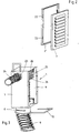
- Fig. 1 shows a perspective view of the housing 1 according to the invention, wherein the individual housing components are shown exploded.
- the housing 1 consists of a surrounding a volume space 2 wall 3. Formed this wall is preferably made of stainless steel.
- the room side, the wall 3 is made open and has a recess 4.
- a flow passage 5, a filter 6 and a cover grille 7 are placed on this recess 4.
- room air can thus reach the volume space 2 enclosed by the housing 1 via the grille 7, the filter 6 and the flow passage 5.
- the flow of air takes place in the opposite direction, ie from the volume space 2 of the housing 1 out the air flows through the flow passage 5, the filter 6 and the grille 7 in the room to be ventilated.
- a connecting piece 8 which serves the arrangement of an air-conveying hose 9.
- the fresh supply air flows through the tube 9 into the volume space 2 of the housing 1 and leaves it through the recess 4, ie flows through the flow passage 5, the filter 6 and the cover 7.
- the spent exhaust air passes through the recess 4 of the housing 1 in the volume space 2, wherein any foreign substances contained in the exhaust air are filtered out via the filter 6, and is then sucked out of the housing interior via the hose 9.
- a securing bracket 10 is provided for secure arrangement of the hose 9 within the connecting piece 8.
- This circlip is introduced into recesses 11 formed on the connection piece, wherein in the completely assembled state it projects through a wave trough of the wave-shaped tube 9. Is achieved by this arrangement a backup of the hose 9 with respect to the connection piece 8, whereby this is fixed in position secure.
- the flow passage 5 has a plurality of passage openings. According to the embodiment according to Fig. 1 are a total of four openings 12 are provided. To regulate the amount of air passing through the passage openings 12 of the flow passage 5 air displaceably arranged cover elements in the form of sliders 13 are provided relative to the flow passage. These slides can be selectively moved to a position desired by the user, whereby this can adjust the size of the total available for the air passages, which at constant pressure for regulating the amount of air passed through the housing leads.
- the in Fig. 1 exemplified flow passage 5 is formed as a frame member and has a total of four openings 12, which are each covered by a fly screen 14. On the longitudinal sides of the frame member, a web 15 is formed in each case. Together, these webs 15 form a flow passage 5 integrally formed filter receptacle, which serves the arrangement of the filter 6.
- the advantage of this embodiment is to be seen in the particularly simple handling, because it is only necessary for an assembly of flow passage 5 and filter 6, the filter 6 between the two arranged on the flow passage 5 webs 15 and the flow passage 5 then together with filter 6 in the recess 4 of the housing 1 to position.
- the filter 6 is used in particular when the housing 1 is used as an exhaust air housing.
- a mounting bracket 16 is arranged on each side of the housing box.
- This mounting bracket is preferably arranged on guided in elongated holes 17 fastening means 18 on the housing 1, so that for the purpose of readjustment, a relative displacement between the housing 1 and mounting bracket 16 can be made.
- this has spring-loaded retaining elements 19.
- these holding elements 19 engage in corresponding recesses 20 formed in the housing interior, which have, for example, the shape of hollow profiled body.
- FIG. 1 illustrated grille 7 is used for over-plaster use.
- the longitudinal slots 22 provided in the lattice frame 21 serve for a possible readjustment of the lattice frame 21 and the louver 7 relative to the housing 1.
- FIG. 3 shows an alternative embodiment of the housing according to the invention. Shown here is a housing arrangement, according to those Fig. 1 corresponds, wherein an additional connecting piece 23 is provided for the arrangement of a further hose 24.
- This type of configuration is used in particular the direct connection of the housing according to the invention to a toilet body or urinal, which advantageously in avoiding mixing with the rest of the room air located in the toilet body or the urinal air can be sucked directly through the housing 1.
- an additional filter holder 25 is provided within the housing 1, which serves to receive a filter 26.
- a partially sectioned side view shows Fig. 4 the embodiment according to Fig. 3 , It can be clearly seen here that the interior of the housing is lined with a sound-absorbing material 27 for sound insulation. In addition, it can be seen that the housing-side end of the tube 9 is provided with a stepped recess 28. This achieves the fact that the air flowing into the interior of the housing through the hose 9 is first deflected by 180 °, before it leaves the volume space 2 via the recess 4, ie the flow passage 5, the filter 6 and the cover grille 7. The advantage of this 180 ° air deflection is the additional noise reduction.
- Fig. 5 schematically shows a double arrangement of the housing according to the invention. Shown are two housing 1, which are connected to each other via a corresponding connecting element 29. To cover both Gezzauseaus traditions 4 either a common or a single cover for each housing may be provided.
- plastic spacer 30 may be arranged on the mounting bracket, as this Fig. 6 can be removed.
Description
- Die Erfindung betrifft eine Anordnung für die Luftdurchführung zur Be- und/oder Entlüftung eines Raumes oder Bereichen hiervon, mit einem Schlauch bzw. einem Rohr und einem Gehäuse mit einem Anschlussstutzen für die Anordnung des strömungstechnisch mit dem Volumeninnenraum des Gehäuses in Verbindung stehenden Schlauches oder Rohres sowie einem raumseitig ausgebildeten, größenvariablen Strömungsdurchlass mit integrierter Filteraufnahme.
- Gehäuse der vorgenannten Art sind aus dem Stand der Technik an sich bekannt und werden sowohl in einer Überputz- als auch in einer Unterputzvariante eingesetzt. Ein gattungsgemäßes Gehäuse ist aus der
US-B1-6,234,893 bekannt. Es dient dazu, Wohn- und/oder Geschäftsräume oder Bereiche hiervon zu belüften, wobei die Luft über in Wänden, Decken oder Böden installierte Blechgehäuse geführt wird. Für eine raumseitige Abdeckung der Gehäuse ist ein demontierbares Gitter vorgesehen, das mittels Schrauben, Stiften oder dergleichen am Blechgehäuse angeordnet ist. Das Gitter dient zugleich als Aufnahme für einen Einsatzfilter. - Von Nachteil bei den vorbekannten Gehäusen ist der Umstand, dass diese ausschließlich für Zuluft oder für Abluft eingesetzt werden können, d. h. es sind unterschiedliche Gehäusetypen für die Verwendung als Zuluftgehäuse bzw. als Abluftgehäuse erforderlich. Zudem ist eine Montage der vorbekannten Gehäuse nur mit entsprechenden Hilfsvorrichtungen möglich, was den Einbau insbesondere zeit- und kostenaufwendig macht. Auch gibt es im Hinblick auf die eingesetzten Fliegengitter Nachteile, da diese aus Montagegründen nicht über ihre gesamte Fläche geschlossen ausgebildet sind, so dass Insekten trotz Anordnung eines Fliegengitters in das Gehäuseinnere gelangen können. Von Nachteil ist des Weiteren, dass die aus dem Stand der Technik bekannten Gehäuse je nach Verwendungszweck zusätzlich verstärkt auszubilden sind. So sind beispielsweise Gehäuse, die in eine Betonwand eingegossen werden, mittels zusätzlicher Stützelemente zu verstärken, damit das Gehäuse infolge der einwirkenden Betonmassen nicht eingedrückt wird.
- Ausgehend vom Vorgenannten ist es Aufgabe der Erfindung, eine Anordnung mit einem Gehäuse bereitzustellen, das gleichermaßen sowohl für die Be- als auch für die Entlüftung eingesetzt werden kann und das über eine genügende Festigkeit verfügt, um ohne den Einsatz zusätzlicher Hilfskonstruktionen auch in Betonwände oder -decken eingegossen zu werden. Darüber hinaus soll ein sicherer Betrieb möglich sein.
- Zur Lösung der Aufgabe wird mit der Erfindung eine Anordnung vorgeschlagen, die dadurch gekennzeichnet ist, dass der Schlauch oder das Rohr im Anschlussstutzen gesichert angeordnet ist, wobei der Schlauch oder das Rohr gewellt ausgebildet ist und zur Sicherung des Schlauches oder des Rohres innerhalb des Anschlussstutzens ein Sicherungsstift in Form eines Bügels vorgesehen ist, der ein Wellental des wellenförmig ausgebildeten Schlauches oder Rohres einerseits als auch im Anschlussstutzen ausgebildete Ausnehmungen andererseits durchragt.
- Das erfindungsgemäße Gehäuse vermag die vorgenannten Nachteile allesamt zu vermeiden.
- Erfindungsgemäß ist der Schlauch oder das Rohr im Anschlussstutzen des Gehäuses gesichert angeordnet. Ein ungewolltes Herausrutschen des in das Gehäuseinnere hineinragenden Schlauch- oder Rohrendes kann so in vorteilhafterweise vermieden werden. Der verwendete Schlauch bzw. das Rohr weist gewellt ausgebildete Schlauch- bzw. Rohrwandungen auf, wodurch in vorteilhafterweise eine auch abgewinkelte Verlegung des Schlauches bzw. des Rohres ermöglicht wird. Zur Sicherung eines solch gewellt ausgebildeten Schlauches bzw. Rohres innerhalb des am Gehäuse angeordneten Anschlussstutzens kann ein Sicherungsstift in Form eines Bügels vorgesehen sein, der zur Sicherung gleichsam ein Wellental des wellenförmig ausgebildeten Schlauches bzw. Rohres einerseits als auch im Anschlußstutzen ausgebildete Ausnehmungen andererseits durchragt. Auf einfache Weise wird so eine sichere Anordnung des gehäuseseitigen Endes des Schlauches oder Rohres innerhalb des Anschlußstutzens gewährleistet.
- Der Strömungsdurchlaß ist als Rahmenteil ausgebildet und in Blickrichtung frontseitig auf das Gehäuse aufgesetzt. Es dient der Anordnung eines keine Montageöffnungen aufweisenden Fliegengitters einerseits und stellt andererseits in Kombination mit relativ verfahrbar angeordneten Abdeckelementen in Form von Schiebern eine einstellbare Luftmengenregulierung dar. Zudem bewirkt die Anordnung des Strömungsdurchlasses eine Verbesserung der statischen Festigkeit des Gehäuses, so daß es auch bei einem Einguß des Gehäuses in eine Betonwand einer zusätzlichen Verstärkung, wie dies bei aus dem Stand der Technik bekannten Gehäusen der Fall ist, nicht bedarf. Von besonderem Vorteil ist ferner, daß das erfindungsgemäße Gehäuse gleichermaßen für die Verwendung als Zuluftgehäuse wie auch als Abluftgehäuse eingesetzt werden kann, denn ist es bei einer geplanten Verwendung als Abluftgehäuse lediglich erforderlich, den Strömungsdurchlaß mit einem entsprechenden Filter zu versehen, weshalb der Strömungsdurchlaß erfindungsgemäß eine integrierte Filteraufnahme aufweist. Bei einer Verwendung des Gehäuses als Zuluftgehäuse ist die Anordnung eines Filters nicht erforderlich, so daß in diesem Falle die integrierte Filteraufnahme des Strömungsdurchlasses ungenutzt bleiben kann.
- Gebildet ist das erfindungsgemäße Gehäuse aus einer einen Volumenraum umgebenden Wandung. Diese Wandung ist raumseitig offen ausgebildet und im Betriebszustand des Gehäuses nach Art eines Deckels mit dem größenvariablen Strömungsdurchlaß verschlossen. Zu- oder Abluft wird so über den Strömungsdurchlaß in das Gehäuseinnere bzw. aus diesem heraus in den zu be- oder entlüftenden Raum geführt. Erfindungsgemäß verfügt das Gehäuse über einen Anschlußstutzen für die Anordnung eines strömungstechnisch mit dem Volumeninnenraum des Gehäuses in Verbindung stehenden Schlauches, Rohres oder dergleichen. Zur Belüftung eines Raumes oder Bereichen hiervon kann also entsprechende Zuluft über den Schlauch in das Gehäuseinnere geführt und von dort aus über den Strömungsdurchlaß in den zu belüftenden Raum eingeführt werden. Im Falle der Verwendung des Gehäuses als Abluftgehäuse wird aus dem zu entlüftenden Raum die verbrauchte Raumluft abgesaugt, wobei diese zunächst über den Strömungsdurchlaß in das Gehäuseinnere gelangt, von wo aus die dann über den strömungstechnisch angeschlossenen Schlauch abgeführt werden kann. Bei der Verwendung des erfindungsgemäßen Gehäuses als Abluftgehäuse ist in die integrativ am Strömungsdurchlaß ausgebildete Filteraufnahme ein entsprechender Filter eingesetzt, so daß die aus dem zu entlüftenden Raum abzuführende Luft zunächst den Filter passiert, bevor sie in das Gehäuseinnere einströmen kann. Die Anordnung des Filters hat dabei den Vorteil, daß in der Raumluft etwaig vorhandene Verunreinigungen ausgefiltert werden können, bevor die angesogene Luft das Gehäuseinnere passiert und durch den strömungstechnisch angeschlossenen Schlauch abgeführt wird. Ungewünschte Verunreinigungen des Gehäuseinneren und des Abluftsystems können so vermieden werden.
- Erfindungsgemäß ist vorgesehen, daß der Strömungsdurchlaß ein mehrere Öffnungen aufweisendes Rahmenelement ist. Abgedeckt sind diese Öffnungen vollständig mit einem Fliegengitter, so daß Insekten wirkungsvoll daran gehindert werden können, in das Gehäuseinnere zu gelangen. Die Abmessungen des Rahmenelements sind derart bemessen, daß es in die die raumseitige Öffnung der Wandung des Gehäuses bildende Ausnehmung eingesetzt werden kann. Dabei sind vorzugsweise die Größe des Rahmenelements einerseits und die Größe der in der Wandung des Gehäuses vorgesehene Ausnehmung andererseits derart aufeinander abgestimmt, daß das Rahmenelement im wesentlichen spaltfrei in die Ausnehmung eingesetzt werden kann. Erreicht wird hierdurch in vorteilhafterweise eine randseitige Abdichtung des Rahmenelements gegenüber dem Gehäuse, so daß die durch den Strömungsdurchlaß hindurchströmende Luft ausschließlich über die hierfür im Strömungsdurchlaß vorgesehenen Öffnungen in das Gehäuseinnere bzw. aus diesem heraus gelangt.
- Gemäß einem weiteren Merkmal der Erfindung weist der Strömungsdurchlaß Abdeckelemente auf, die zur zumindest teilweisen Abdeckung der im Strömungsdurchlaß vorgesehenen Öffnungen verschieblich angeordnet sind. Diese Abdeckelemente sind vorzugsweise als Schieber ausgebildet und dienen der Regulierung der durch den Strömungsdurchlaß hindurchströmenden Luftmenge bei gegebenem Druck. Auf diese Weise kann eine exakte Einstellung der vom Anwender wunschgemäß geforderten Luftmengenzirkulation vorgenommen werden.
- Gemäß einem weiteren Merkmal der Erfindung ist die Filteraufnahme durch zwei am Strömungsdurchlaß ausgebildete Stege gebildet. Diese Stege befinden sich vorzugsweise längsseitig am den Strömungsdurchlaß bildenden Rahmenelement. Die Höhe der Stege entspricht dabei vorzugsweise der Höhe des Filters, so daß bei eingesetztem Filter eine im wesentlichen plane Abschlußfläche entsteht. Die Anordnung zweier Stege hat dabei den Vorteil, daß das Filterelement auf einfache Weise eingesetzt bzw. ausgetauscht werden kann. Die Handhabung des Gehäuses ist somit auch in Bezug auf die Anordnung des Filters denkbar einfach.
- Gemäß einem weiteren Merkmal der Erfindung weist das Gehäuse zumindest einen Montagewinkel auf. Dieser Montagewinkel ist außenseitig des Gehäuses verschieblich an diesem angeordnet und dient der Fixierung des Gehäuses im Einbauraum. Vorzugsweise verfügt das Gehäuse über zwei Montagewinkel, die jeweils an den gegenüberliegenden Längsseiten des Gehäuses angeordnet sind.
- Gemäß einem weiteren Merkmal der Erfindung sind zur Schalldämmung Schalldämmelemente vorgesehen, die als schallabsorbierendes Material im Innenraum des Gehäuses angeordnet sind. Für eine weitere Schalldämmung kann vorgesehen sein, das in den Innenraum des Gehäuses hineinragende Ende des luftführendes Schlauches bzw. Rohres derart auszuformen, daß die über den Schlauch bzw. das Rohr einströmende Luft um 180° umgelenkt wird, bevor sie zur Austrittsöffnung des Gehäuses gelangt. Erreicht werden kann dies beispielsweise durch eine endseitig in den Schlauch oder das Rohr eingeformte Klinke oder treppenförmige Ausnehmung.
- Gemäß einem weiteren Merkmal der Erfindung ist ein Abdeckgitter vorgesehen, das frontseitig auf den Strömungsdurchlaß aufsetzbar ist. Je nach Ausgestaltung kann dabei das Abdeckgitter sowohl in Form einer Überputzvariante als auch in Form einer Unterputzvariante ausgebildet sein. Lösbar angeordnet ist das Abdeckgitter vorzugsweise mittels federelastischer Halteelemente. Diese federelastischen Halteelemente greifen in korrespondierend ausgebildete Aufnahmen ein, die gehäuseinnenseitig ausgebildet sind. Von besonderem Vorteil bei dieser Art der Anordnung ist der Umstand, daß keinerlei Montagelöcher oder Ausnehmungen innerhalb des Strömungsdurchlasses vorzusehen sind, durch die hindurch ungewollt Verunreinigungen, Insekten oder dergleichen in das Volumeninnere des Gehäuses eintreten könnten.
- Die Rahmen zur Montage der Unterputzgitter sind vorzugsweise mit Schlitzen ausgebildet, so daß sie auf die bauseitigen Schenkel der Montagewinkel aufgeschraubt werden können und sich so beidseits gegenüber dem Gehäuse verdrehen bzw. verschieben lassen. Hierdurch wird erreicht, daß trotz einer unter Umständen unpräzise Montage des Gehäuses der Gitterrahmen präziser in Relation zur Montagewand ausgerichtet werden kann.
- Gemäß einem weiteren Merkmal der Erfindung ist ein zusätzlicher Anschlußstutzen für die Anordnung eines weiteren Schlauches, Rohres oder dergleichen vorgesehen. Die Ausgestaltung eines weiteren Anschlußstutzens ermöglicht den Direktanschluß des Gehäuses an eine WC-Schüssel oder ein Urinal. Die im Volumenraum eines Toilettenkörpers oder eines Urinals befindliche Luft kann auf diese Weise direkt über das erfindungsgemäße Gehäuse abgesaugt werden. Somit kann in vorteilhafterweise eine Vermischung der aus einem Toilettenkörper oder einem Urinal stammenden Luft mit der übrigen Raumluft vermieden werden, was insbesondere unter dem Gesichtspunkt der Geruchsbelästigung von Vorteil ist.
- Innerhalb des Gehäuses kann gemäß einem weiteren Merkmal der Erfindung eine zusätzliche Filteraufnahme angeordnet sein. Diese dient dazu, einen weiteren Filter aufzunehmen, der die aus dem im zweiten Anschluß angeordneten Schlauch stammende Luft filtert, bevor diese in den Volumeninnenraum des Gehäuses eindringt. Die Anordnung einer solchen Filteraufnahme eignet sich insbesondere bei dem Anschluß des Gehäuses an einen Toilettenkörper oder ein Urinal.
- Weitere Merkmale und Vorteile der Erfindung ergeben sich aus der Beschreibung anhand der nachfolgenden Figuren. Hierbei zeigen:
- Fig. 1:
- in einer schematischen, perspektivischen Darstellung das erfindungsgemäße Gehäuse;
- Fig. 2:
- in einer perspektivischen Darstellung ein Abdeckgitter gemäß einer alternativen Ausgestaltungsform;
- Fig. 3:
- in einer schematischen, perspektivischen Darstellung das erfindungsgemäße Gehäuse gemäß einer alternativen Ausgestaltungsform;
- Fig. 4:
- in einer teilgeschnittenen Seitenansicht das erfindungsgemäße Gehäuse gemäß
Fig. 3 ; - Fig. 5:
- in einer schematischen, perspektivischen Darstellung eine weitere Ausgestaltungsform des Gehäuses und
- Fig. 6:
- in einer schematischen, perspektivischen Darstellung das erfindungsgemäße Gehäuse in Seitenansicht.
-
Fig. 1 zeigt in perspektivischer Darstellung das erfindungsgemäße Gehäuse 1, wobei die einzelnen Gehäusebestandteile explosionsartig dargestellt sind. Das Gehäuse 1 besteht aus einer einen Volumenraum 2 umgebenden Wandung 3. Gebildet ist diese Wandung vorzugsweise aus nicht rostendem Stahlblech. Raumseitig ist die Wandung 3 offen ausgeführt und weist eine Ausnehmung 4 auf. In Form eines Deckels werden auf diese Ausnehmung 4 aufgesetzt ein Strömungsdurchlaß 5, ein Filter 6 sowie ein Abdeckgitter 7. In montiertem Zustand kann also Raumluft über das Abdeckgitter 7, den Filter 6 und den Strömungsdurchlaß 5 in den vom Gehäuse 1 umschlossenen Volumenraum 2 gelangen. Im Falle der Raumbelüftung erfolgt die Strömung der Luft in entgegengesetzter Richtung, d.h. aus dem Volumenraum 2 des Gehäuses 1 heraus strömt die Luft über den Strömungsdurchlaß 5, den Filter 6 sowie das Abdeckgitter 7 in den zu belüftenden Raum. - An der in
Fig. 1 dargestellten unteren Seite des Gehäuses 1 ist ein Anschlußstutzen 8 vorgesehen, der der Anordnung eines luftführenden Schlauches 9 dient. Im Falle der Belüftung eines Raumes strömt die frische Zuluft durch den Schlauch 9 in den Volumenraum 2 des Gehäuses 1 hinein und verläßt diesen über die Ausnehmung 4, d.h. durchströmt den Strömungsdurchlaß 5, den Filter 6 sowie das Abdeckelement 7. Im Falle der Entlüftung eines Raumes gelangt die verbrauchte Abluft über die Ausnehmung 4 des Gehäuses 1 in den Volumenraum 2, wobei sich etwaig in der Abluft befindliche Fremdstoffe über den Filter 6 ausgefiltert werden, und wird sodann über den Schlauch 9 aus dem Gehäuseinneren abgesogen. - Zur sicheren Anordnung des Schlauches 9 innerhalb des Anschlußstutzens 8 ist ein Sicherungsbügel 10 vorgesehen. Dieser Sicherungsbügel wird in am Anschlußstutzen ausgebildete Ausnehmungen 11 eingeführt, wobei er im fertig montierten Zustand ein Wellental des wellenartig ausgebildeten Schlauches 9 durchragt. Erzielt wird durch diese Anordnung eine Sicherung des Schlauches 9 gegenüber dem Anschlußstutzen 8, womit dieser lagesicher fixiert ist.
- Der Strömungsdurchlaß 5 verfügt über eine Mehrzahl von Durchtrittsöffnungen. Gemäß dem Ausführungsbeispiel nach
Fig. 1 sind insgesamt vier Durchtrittsöffnungen 12 vorgesehen. Zur Regulierung der Luftmenge der durch die Durchtrittsöffnungen 12 des Strömungsdurchlasses 5 hindurchströmenden Luft sind relativ zum Strömungsdurchlaß 5 verschieblich angeordnete Abdeckelemente in Form von Schiebern 13 vorgesehen. Diese Schieber können wahlweise in eine vom Anwender gewünschte Position verschoben werden, womit dieser die Größe der für die Luft insgesamt zur Verfügung stehenden Durchtrittsöffnungen einstellen kann, was bei gleichbleibendem Druck zur Regulierung der durch das Gehäuse hindurchgeführten Luftmenge führt. - Vollständig verschlossen sind die Durchtrittsöffnungen 12 des Strömungsdurchlasses 5 mit einem Fliegengitter 14. Wirkungsvoll kann hindurch das ungewollte Eindringen von Fliegen, Insekten oder dergleichen in das Gehäuseinnere unterbunden werden.
- Der in
Fig. 1 beispielhaft dargestellte Strömungsdurchlaß 5 ist als Rahmenelement ausgebildet und weist insgesamt vier Durchtrittsöffnungen 12 auf, die jeweils durch ein Fliegengitter 14 abgedeckt sind. An den Längsseiten des Rahmenelements ist jeweils ein Steg 15 ausgebildet. Zusammen bilden diese Stege 15 eine am Strömungsdurchlaß 5 integriert ausgebildete Filteraufnahme, die der Anordnung des Filters 6 dient. Der Vorteil dieser Ausgestaltung ist in der besonders einfachen Handhabung zu sehen, denn ist es für eine Montage von Strömungsdurchlaß 5 und Filter 6 lediglich erforderlich, den Filter 6 zwischen die beiden am Strömungsdurchlaß 5 angeordneten Stege 15 zwischenzuordnen und den Strömungsdurchlaß 5 sodann samt Filter 6 in der Ausnehmung 4 des Gehäuses 1 zu positionieren. Verwendet wird der Filter 6 insbesondere bei einem Einsatz des Gehäuses 1 als Abluftgehäuse. In diesem Fall wird nämlich die im Raum befindliche Abluft angesogen und zur Ausfilterung etwaig in der Abluft befindliche Fremdstoffe zunächst über den Filter 6 geleitet, bevor diese dann in den Innenraum des Gehäuses 1 gelangt. Bei der Verwendung des Gehäuses als Zuluftgehäuse ist die Anordnung eines Filters 6 nicht erforderlich, denn ist die in den zu belüftenden Raum einzuführende Frischluft frei von irgendwelchen Fremdstoffen. - Zur Anordnung des Gehäuses innerhalb einer in einer Wand oder einer Decke vorgesehenen Ausnehmung ist beidseitig des Gehäusekasten jeweils ein Montagewinkel 16 angeordnet. Dieser Montagewinkel ist vorzugsweise über in Langlöchern 17 geführte Befestigungsmittel 18 am Gehäuse 1 angeordnet, so daß zum Zweck einer Nachjustage eine Relativverschiebung zwischen Gehäuse 1 und Montagewinkel 16 vorgenommen werden kann.
- Zur lagesicheren Anordnung des Abdeckgitters 7 verfügt dieses über federbelastete Halteelemente 19. Im montierten Zustand des Gehäuses 1 greifen diese Halteelemente 19 in korrespondierend im Gehäuseinneren ausgebildete Ausnehmungen 20 ein, die beispielsweise die Form hohl ausgebildeter Profilkörper aufweisen.
- Das in
Fig. 1 dargestellte Abdeckgitter 7 dient der Überputz-Verwendung. Für den Fall der Unterputzanordnung ist das inFig. 2 dargestellte Abdeckgitter 7 zu verwenden. Dieses wird im Unterschied zu dem inFig. 1 dargestellten Abdeckgitter unter Verwendung eines zusätzlichen Gitterrahmens 21 am Gehäuse 1 angeordnet. Die im Gitterrahmen 21 vorgesehen Längsschlitze 22 dienen dabei einer möglichen Nachjustage von Gitterrahmen 21 und Abdeckgitter 7 gegenüber dem Gehäuse 1. -
Fig. 3 zeigt eine alternative Ausgestaltungsform des erfindungsgemäßen Gehäuses. Gezeigt ist hier eine Gehäuseanordnung, die derjenigen nachFig. 1 entspricht, wobei ein zusätzlicher Anschlußstutzen 23 zur Anordnung eines weiteren Schlauches 24 vorgesehen ist. Diese Art der Ausgestaltung dient insbesondere dem Direktanschluß des erfindungsgemäßen Gehäuses an einen Toilettenkörper oder ein Urinal, womit in vorteilhafterweise unter Vermeidung einer Durchmischung mit der übrigen Raumluft die im Toilettenkörper oder dem Urinal befindliche Luft direkt über das Gehäuse 1 abgesogen werden kann. Zur Filtrierung der aus einem Toilettenkörper oder einem Urinal stammenden Luft ist innerhalb des Gehäuses 1 eine zusätzliche Filteraufnahme 25 vorgesehen, die der Aufnahme eines Filters 26 dient. - In einer teilgeschnittenen Seitenansicht zeigt
Fig. 4 das Ausführungsbeispiel nachFig. 3 . Deutlich zu erkennen ist hier, daß der Innenraum des Gehäuses zur Schalldämmung mit einem schallabsorbierenden Material 27 ausgekleidet ist. Zudem ist zu erkennen, daß das gehäuseseitige Ende des Schlauches 9 mit einer treppenförmigen Ausnehmung 28 versehen ist. Erreicht wird hierdurch, daß die in den Gehäuseinnenraum durch den Schlauch 9 hineinströmende Luft zunächst um 180° umgelenkt wird, bevor sie über die Ausnehmung 4, d. h. den Strömungsdurchlaß 5, den Filter 6 und das Abdeckgitter 7 den Volumenraum 2 verläßt. Vorteil dieser 180° Luftumlenkung ist die sich zusätzlich einstellende Geräuschreduzierung. -
Fig. 5 zeigt schematisch eine Doppelanordnung des erfindungsgemäßen Gehäuses. Dargestellt sind zwei Gehäuse 1, die über ein entsprechendes Verbindungselement 29 miteinander verbunden sind. Zur Abdeckung beider Gehäuseausnehmungen 4 kann entweder eine gemeinsame oder aber eine für jedes Gehäuse einzelne Abdeckung vorgesehen sein. - Zur Vermeidung von Korrosionsspuren können am Montagewinkel 16 Kunststoffdistanzhalter 30 angeordnet sein, wie dies
Fig. 6 entnommen werden kann. -
- 1
- Gehäuse
- 2
- Volumenraum
- 3
- Wandung
- 4
- Ausnehmung
- 5
- Strömungsdurchlaß
- 6
- Filter
- 7
- Abdeckgitter
- 8
- Anschlußstutzen
- 9
- Schlauch
- 10
- Sicherungsbügel
- 11
- Ausnehmung
- 12
- Durchtrittsöffnung
- 13
- Schieber
- 14
- Fliegengitter
- 15
- Steg
- 16
- Montagewinkel
- 17
- Langloch
- 18
- Befestigungsmittel
- 19
- Halteelement
- 20
- Ausnehmung
- 21
- Gitterrahmen
- 22
- Längsschlitz
- 23
- Anschlußstutzen
- 24
- Schlauch
- 25
- Filteraufnahme
- 26
- Filter
- 27
- schallabsorbierendes Material
- 28
- Ausnehmung
- 29
- Verbindungselement
- 30
- Kunststoffdistanzhalter
Claims (13)
- Anordnung für die Luftdurchführung zur Be- und/oder Entlüftung eines Raums oder Bereichen hiervon, mit einem Schlauch (9) bzw. einem Rohr und einem Gehäuse mit einem Anschlussstutzen (8) für die Anordnung des strömungstechnisch mit dem Volumeninnenraum (2) des Gehäuses (1) in Verbindung stehenden Schlauches (9) oder Rohres sowie einem raumseitig ausgebildeten, größenvariablen Strömungsdurchlass (5) mit integrierter Filteraufnahme,
dadurch gekennzeichnet,
dass der Schlauch (9) oder das Rohr im Anschlussstutzen (8) gesichert angeordnet ist, wobei der Schlauch (9) oder das Rohr gewellt ausgebildet ist und zur Sicherung des Schlauches (9) oder des Rohres innerhalb des Anschlussstutzens (8) ein Sicherungsstift in Form eines Bügels (10) vorgesehen ist, der ein Wellental des wellenförmig ausgebildeten Schlauches (9) oder Rohres einerseits als auch im Anschlussstutzen (8) ausgebildete Ausnehmungen (11) andererseits durchragt. - Anordnung nach Anspruch 1, dadurch gekennzeichnet, dass der Strömungsdurchlass des Gehäuses ein mehrere Öffnungen (12) aufweisendes Rahmenelement ist.
- Anordnung nach Anspruch 2, dadurch gekennzeichnet, dass die Öffnungen (12) des Gehäuses mit einem Fliegengitter (14) vollständig abgedeckt sind.
- Anordnung nach einem der vorhergehenden Ansprüche 2 oder 3, dadurch gekennzeichnet, dass der Strömungsdurchlass des Gehäuses Abdeckelemente (13) aufweist, die zur zumindest teilweisen Abdeckung der Öffnungen (12) verschieblich angeordnet sind.
- Anordnung nach einem der vorhergehenden Ansprüche, dadurch gekennzeichnet, dass die Filteraufnahme des Gehäuses durch zwei am Strömungsdurchlass ausgebildete Stege (15) gebildet ist.
- Anordnung nach einem der vorhergehenden Ansprüche, gekennzeichnet durch wenigstens einen Montagewinkel (16).
- Anordnung nach Anspruch 6, dadurch gekennzeichnet, dass der Montagewinkel (16) gehäuseseitig Langlöcher (17) aufweist.
- Anordnung nach einem der vorhergehenden Ansprüche, gekennzeichnet durch Schalldämmelemente (27).
- Anordnung nach einem der vorhergehenden Ansprüche, gekennzeichnet durch ein Abdeckgitter (7).
- Anordnung nach Anspruch 9, dadurch gekennzeichnet, dass das Abdeckgitter (7) federelastische Halteelemente (19) zur auswechselbaren Anordnung am Gehäuse (1) aufweist.
- Unordnung nach Anspruch 10, gekennzeichnet durch korrespondierend zu den Halteelementen (19) ausgebildete Aufnahmen.
- Anordnung nach einem der vorhergehenden Ansprüche, gekennzeichnet durch einen weiteren Anschlussstutzen (23) am Gehäuse für die Anordnung eines Schlauches (24) oder Rohres.
- Anordnung nach einem der vorhergehenden Ansprüche, gekennzeichnet durch eine im Gehäuseinneren angeordnete Filteraufnahme (25).
Priority Applications (1)
| Application Number | Priority Date | Filing Date | Title |
|---|---|---|---|
| PL04008662T PL1471313T3 (pl) | 2003-04-25 | 2004-04-10 | Obudowa do przeprowadzania powietrza |
Applications Claiming Priority (2)
| Application Number | Priority Date | Filing Date | Title |
|---|---|---|---|
| DE20306453U | 2003-04-25 | ||
| DE20306453U DE20306453U1 (de) | 2003-04-25 | 2003-04-25 | Gehäuse für die Luftdurchführung |
Publications (2)
| Publication Number | Publication Date |
|---|---|
| EP1471313A1 EP1471313A1 (de) | 2004-10-27 |
| EP1471313B1 true EP1471313B1 (de) | 2018-02-07 |
Family
ID=27763146
Family Applications (1)
| Application Number | Title | Priority Date | Filing Date |
|---|---|---|---|
| EP04008662.1A Expired - Lifetime EP1471313B1 (de) | 2003-04-25 | 2004-04-10 | Gehäuse für die Luftdurchführung |
Country Status (4)
| Country | Link |
|---|---|
| EP (1) | EP1471313B1 (de) |
| DE (1) | DE20306453U1 (de) |
| ES (1) | ES2666159T3 (de) |
| PL (1) | PL1471313T3 (de) |
Families Citing this family (4)
| Publication number | Priority date | Publication date | Assignee | Title |
|---|---|---|---|---|
| DE202005003475U1 (de) * | 2005-03-04 | 2005-05-25 | Zehnder Verkaufs- Und Verwaltungs Ag | Gehäuse für die Luftdurchführung |
| DE202010014480U1 (de) * | 2010-10-19 | 2010-12-23 | Zehnder Verkaufs- Und Verwaltungs Ag | Kupplungsmuffe |
| IT201600078849A1 (it) * | 2016-07-27 | 2018-01-27 | Ideal Clima Srl | Procedimento per realizzare una bocchetta nascosta migliorata per impianti di ventilazione, riscaldamento e climatizzazione, e assieme bocchetta per attuare tale procedimento. |
| EP3536876B1 (de) | 2018-03-08 | 2020-09-30 | Hoval Aktiengesellschaft | Lüftungsgehäuse-schutzabdeckung |
Family Cites Families (4)
| Publication number | Priority date | Publication date | Assignee | Title |
|---|---|---|---|---|
| US4407187A (en) * | 1981-12-15 | 1983-10-04 | Horney Robert W | Air control device |
| US5472380A (en) * | 1994-05-26 | 1995-12-05 | Sarazen, Jr.; Paul M. | Modular forced-air floor register with filter |
| US6234893B1 (en) | 2000-07-01 | 2001-05-22 | Jerry R. Meredith | Vent device for use with medium for altering a condition of air entering an environment |
| BE1014264A3 (nl) * | 2001-06-22 | 2003-07-01 | Oroplastic Nv | Kunststof planchet en werkwijze voor het vervaardigen ervan. |
-
2003
- 2003-04-25 DE DE20306453U patent/DE20306453U1/de not_active Expired - Lifetime
-
2004
- 2004-04-10 PL PL04008662T patent/PL1471313T3/pl unknown
- 2004-04-10 EP EP04008662.1A patent/EP1471313B1/de not_active Expired - Lifetime
- 2004-04-10 ES ES04008662.1T patent/ES2666159T3/es not_active Expired - Lifetime
Non-Patent Citations (1)
| Title |
|---|
| None * |
Also Published As
| Publication number | Publication date |
|---|---|
| ES2666159T3 (es) | 2018-05-03 |
| PL1471313T3 (pl) | 2018-07-31 |
| DE20306453U1 (de) | 2003-08-14 |
| EP1471313A1 (de) | 2004-10-27 |
Similar Documents
| Publication | Publication Date | Title |
|---|---|---|
| DE102004042291B4 (de) | Höhenverstelleinrichtung für eine deckenbefestigte Dunstabzugshaube sowie Dunstabzugshaube | |
| DE102007008019B4 (de) | Luftauslass | |
| DE202006009355U1 (de) | Filterlüfter mit einer Schnellbefestigungseinrichtung | |
| DE4312664C1 (de) | Filterlüfter | |
| DE4317734A1 (de) | Vorrichtung zur Verteilung und selbsttätigen Regelung durchgesetzter Luftmengen, insbesondere für die Belüftung von Räumlichkeiten | |
| DE202005004307U1 (de) | Inseldunstabzugshaube | |
| EP1698838B1 (de) | Gehäuse für die Luftdurchführung | |
| DE2742734A1 (de) | Axialventilator | |
| EP1471313B1 (de) | Gehäuse für die Luftdurchführung | |
| EP2286153B1 (de) | Umluftweiche | |
| DE2531247A1 (de) | Frischluftschleuse zur belueftung von raeumen | |
| DE102014016878A1 (de) | Klimaanlage mit Windschild | |
| DE19752019A1 (de) | Belüftungsvorrichtung und Belüftungssystem | |
| EP2708827B1 (de) | Luftaus- oder -einlass und Lüftungssystem hiermit | |
| DE20122340U1 (de) | Dunstabzugshaube | |
| EP1498569B1 (de) | Türdichtung | |
| EP3361175A1 (de) | Deckenelement, insbesondere einer kühl- oder heizdecke | |
| DE4232315A1 (de) | Zulufteinrichtung zum Einbau in Außenwänden von Gebäuden und/oder Wohnungen | |
| EP3124869B1 (de) | Luftauslassgitter, insbesondere für einen ofen | |
| DE202006017606U1 (de) | Türanordnung | |
| DE102006062986B3 (de) | Sanitäre Auslaufarmatur mit einem Strahlregler | |
| CH682012A5 (en) | Motor driven bathroom ventilator | |
| DE10106646C1 (de) | Mauerkasten für Abluft- und Zuluft-Durchleitung durch eine Wand | |
| DE3025441A1 (de) | Aussenwandkasten fuer die verbrennungsluft- und abgaskanaele eines mit einem brennersystem arbeitenden geraetes | |
| EP0236683B1 (de) | Lufteinlass-, Luftauslass- und/oder Luftverteilervorrichtung, insbesondere Lüftungsvorrichtung für Räume |
Legal Events
| Date | Code | Title | Description |
|---|---|---|---|
| PUAI | Public reference made under article 153(3) epc to a published international application that has entered the european phase |
Free format text: ORIGINAL CODE: 0009012 |
|
| AK | Designated contracting states |
Kind code of ref document: A1 Designated state(s): AT BE BG CH CY CZ DE DK EE ES FI FR GB GR HU IE IT LI LU MC NL PL PT RO SE SI SK TR |
|
| AX | Request for extension of the european patent |
Extension state: AL HR LT LV MK |
|
| 17P | Request for examination filed |
Effective date: 20041119 |
|
| AKX | Designation fees paid |
Designated state(s): AT BE BG CH CY CZ DE DK EE ES FI FR GB GR HU IE IT LI LU MC NL PL PT RO SE SI SK TR |
|
| 17Q | First examination report despatched |
Effective date: 20090709 |
|
| RAP1 | Party data changed (applicant data changed or rights of an application transferred) |
Owner name: ZEHNDER GROUP INTERNATIONAL AG |
|
| GRAP | Despatch of communication of intention to grant a patent |
Free format text: ORIGINAL CODE: EPIDOSNIGR1 |
|
| STAA | Information on the status of an ep patent application or granted ep patent |
Free format text: STATUS: GRANT OF PATENT IS INTENDED |
|
| INTG | Intention to grant announced |
Effective date: 20170904 |
|
| GRAS | Grant fee paid |
Free format text: ORIGINAL CODE: EPIDOSNIGR3 |
|
| GRAA | (expected) grant |
Free format text: ORIGINAL CODE: 0009210 |
|
| STAA | Information on the status of an ep patent application or granted ep patent |
Free format text: STATUS: THE PATENT HAS BEEN GRANTED |
|
| AK | Designated contracting states |
Kind code of ref document: B1 Designated state(s): AT BE BG CH CY CZ DE DK EE ES FI FR GB GR HU IE IT LI LU MC NL PL PT RO SE SI SK TR |
|
| REG | Reference to a national code |
Ref country code: GB Ref legal event code: FG4D Free format text: NOT ENGLISH |
|
| REG | Reference to a national code |
Ref country code: AT Ref legal event code: REF Ref document number: 968964 Country of ref document: AT Kind code of ref document: T Effective date: 20180215 Ref country code: CH Ref legal event code: EP |
|
| REG | Reference to a national code |
Ref country code: IE Ref legal event code: FG4D Free format text: LANGUAGE OF EP DOCUMENT: GERMAN |
|
| REG | Reference to a national code |
Ref country code: DE Ref legal event code: R096 Ref document number: 502004015643 Country of ref document: DE |
|
| REG | Reference to a national code |
Ref country code: FR Ref legal event code: PLFP Year of fee payment: 15 |
|
| REG | Reference to a national code |
Ref country code: ES Ref legal event code: FG2A Ref document number: 2666159 Country of ref document: ES Kind code of ref document: T3 Effective date: 20180503 |
|
| REG | Reference to a national code |
Ref country code: NL Ref legal event code: FP |
|
| PG25 | Lapsed in a contracting state [announced via postgrant information from national office to epo] |
Ref country code: CY Free format text: LAPSE BECAUSE OF FAILURE TO SUBMIT A TRANSLATION OF THE DESCRIPTION OR TO PAY THE FEE WITHIN THE PRESCRIBED TIME-LIMIT Effective date: 20180207 Ref country code: FI Free format text: LAPSE BECAUSE OF FAILURE TO SUBMIT A TRANSLATION OF THE DESCRIPTION OR TO PAY THE FEE WITHIN THE PRESCRIBED TIME-LIMIT Effective date: 20180207 |
|
| PG25 | Lapsed in a contracting state [announced via postgrant information from national office to epo] |
Ref country code: SE Free format text: LAPSE BECAUSE OF FAILURE TO SUBMIT A TRANSLATION OF THE DESCRIPTION OR TO PAY THE FEE WITHIN THE PRESCRIBED TIME-LIMIT Effective date: 20180207 Ref country code: BG Free format text: LAPSE BECAUSE OF FAILURE TO SUBMIT A TRANSLATION OF THE DESCRIPTION OR TO PAY THE FEE WITHIN THE PRESCRIBED TIME-LIMIT Effective date: 20180507 Ref country code: GR Free format text: LAPSE BECAUSE OF FAILURE TO SUBMIT A TRANSLATION OF THE DESCRIPTION OR TO PAY THE FEE WITHIN THE PRESCRIBED TIME-LIMIT Effective date: 20180508 |
|
| PG25 | Lapsed in a contracting state [announced via postgrant information from national office to epo] |
Ref country code: RO Free format text: LAPSE BECAUSE OF FAILURE TO SUBMIT A TRANSLATION OF THE DESCRIPTION OR TO PAY THE FEE WITHIN THE PRESCRIBED TIME-LIMIT Effective date: 20180207 Ref country code: EE Free format text: LAPSE BECAUSE OF FAILURE TO SUBMIT A TRANSLATION OF THE DESCRIPTION OR TO PAY THE FEE WITHIN THE PRESCRIBED TIME-LIMIT Effective date: 20180207 |
|
| REG | Reference to a national code |
Ref country code: DE Ref legal event code: R097 Ref document number: 502004015643 Country of ref document: DE |
|
| PG25 | Lapsed in a contracting state [announced via postgrant information from national office to epo] |
Ref country code: SK Free format text: LAPSE BECAUSE OF FAILURE TO SUBMIT A TRANSLATION OF THE DESCRIPTION OR TO PAY THE FEE WITHIN THE PRESCRIBED TIME-LIMIT Effective date: 20180207 Ref country code: DK Free format text: LAPSE BECAUSE OF FAILURE TO SUBMIT A TRANSLATION OF THE DESCRIPTION OR TO PAY THE FEE WITHIN THE PRESCRIBED TIME-LIMIT Effective date: 20180207 Ref country code: MC Free format text: LAPSE BECAUSE OF FAILURE TO SUBMIT A TRANSLATION OF THE DESCRIPTION OR TO PAY THE FEE WITHIN THE PRESCRIBED TIME-LIMIT Effective date: 20180207 Ref country code: CZ Free format text: LAPSE BECAUSE OF FAILURE TO SUBMIT A TRANSLATION OF THE DESCRIPTION OR TO PAY THE FEE WITHIN THE PRESCRIBED TIME-LIMIT Effective date: 20180207 |
|
| PLBE | No opposition filed within time limit |
Free format text: ORIGINAL CODE: 0009261 |
|
| STAA | Information on the status of an ep patent application or granted ep patent |
Free format text: STATUS: NO OPPOSITION FILED WITHIN TIME LIMIT |
|
| 26N | No opposition filed |
Effective date: 20181108 |
|
| REG | Reference to a national code |
Ref country code: IE Ref legal event code: MM4A |
|
| PG25 | Lapsed in a contracting state [announced via postgrant information from national office to epo] |
Ref country code: LU Free format text: LAPSE BECAUSE OF NON-PAYMENT OF DUE FEES Effective date: 20180410 |
|
| PG25 | Lapsed in a contracting state [announced via postgrant information from national office to epo] |
Ref country code: SI Free format text: LAPSE BECAUSE OF FAILURE TO SUBMIT A TRANSLATION OF THE DESCRIPTION OR TO PAY THE FEE WITHIN THE PRESCRIBED TIME-LIMIT Effective date: 20180207 |
|
| PG25 | Lapsed in a contracting state [announced via postgrant information from national office to epo] |
Ref country code: IE Free format text: LAPSE BECAUSE OF NON-PAYMENT OF DUE FEES Effective date: 20180410 |
|
| REG | Reference to a national code |
Ref country code: AT Ref legal event code: MM01 Ref document number: 968964 Country of ref document: AT Kind code of ref document: T Effective date: 20180410 |
|
| PG25 | Lapsed in a contracting state [announced via postgrant information from national office to epo] |
Ref country code: AT Free format text: LAPSE BECAUSE OF NON-PAYMENT OF DUE FEES Effective date: 20180410 |
|
| PG25 | Lapsed in a contracting state [announced via postgrant information from national office to epo] |
Ref country code: TR Free format text: LAPSE BECAUSE OF FAILURE TO SUBMIT A TRANSLATION OF THE DESCRIPTION OR TO PAY THE FEE WITHIN THE PRESCRIBED TIME-LIMIT Effective date: 20180207 |
|
| PG25 | Lapsed in a contracting state [announced via postgrant information from national office to epo] |
Ref country code: PT Free format text: LAPSE BECAUSE OF FAILURE TO SUBMIT A TRANSLATION OF THE DESCRIPTION OR TO PAY THE FEE WITHIN THE PRESCRIBED TIME-LIMIT Effective date: 20180207 Ref country code: HU Free format text: LAPSE BECAUSE OF FAILURE TO SUBMIT A TRANSLATION OF THE DESCRIPTION OR TO PAY THE FEE WITHIN THE PRESCRIBED TIME-LIMIT; INVALID AB INITIO Effective date: 20040410 |
|
| PGFP | Annual fee paid to national office [announced via postgrant information from national office to epo] |
Ref country code: NL Payment date: 20220420 Year of fee payment: 19 |
|
| PGFP | Annual fee paid to national office [announced via postgrant information from national office to epo] |
Ref country code: IT Payment date: 20220420 Year of fee payment: 19 Ref country code: GB Payment date: 20220420 Year of fee payment: 19 Ref country code: FR Payment date: 20220420 Year of fee payment: 19 Ref country code: ES Payment date: 20220629 Year of fee payment: 19 Ref country code: DE Payment date: 20220420 Year of fee payment: 19 |
|
| PGFP | Annual fee paid to national office [announced via postgrant information from national office to epo] |
Ref country code: PL Payment date: 20220404 Year of fee payment: 19 Ref country code: CH Payment date: 20220421 Year of fee payment: 19 Ref country code: BE Payment date: 20220421 Year of fee payment: 19 |
|
| REG | Reference to a national code |
Ref country code: DE Ref legal event code: R119 Ref document number: 502004015643 Country of ref document: DE |
|
| REG | Reference to a national code |
Ref country code: CH Ref legal event code: PL |
|
| REG | Reference to a national code |
Ref country code: NL Ref legal event code: MM Effective date: 20230501 |
|
| GBPC | Gb: european patent ceased through non-payment of renewal fee |
Effective date: 20230410 |
|
| REG | Reference to a national code |
Ref country code: BE Ref legal event code: MM Effective date: 20230430 |
|
| PG25 | Lapsed in a contracting state [announced via postgrant information from national office to epo] |
Ref country code: GB Free format text: LAPSE BECAUSE OF NON-PAYMENT OF DUE FEES Effective date: 20230410 |
|
| PG25 | Lapsed in a contracting state [announced via postgrant information from national office to epo] |
Ref country code: NL Free format text: LAPSE BECAUSE OF NON-PAYMENT OF DUE FEES Effective date: 20230501 Ref country code: LI Free format text: LAPSE BECAUSE OF NON-PAYMENT OF DUE FEES Effective date: 20230430 Ref country code: GB Free format text: LAPSE BECAUSE OF NON-PAYMENT OF DUE FEES Effective date: 20230410 Ref country code: FR Free format text: LAPSE BECAUSE OF NON-PAYMENT OF DUE FEES Effective date: 20230430 Ref country code: DE Free format text: LAPSE BECAUSE OF NON-PAYMENT OF DUE FEES Effective date: 20231103 Ref country code: CH Free format text: LAPSE BECAUSE OF NON-PAYMENT OF DUE FEES Effective date: 20230430 |
|
| PG25 | Lapsed in a contracting state [announced via postgrant information from national office to epo] |
Ref country code: BE Free format text: LAPSE BECAUSE OF NON-PAYMENT OF DUE FEES Effective date: 20230430 |