EP1464693A2 - Leckdetektion bei Brennstoffzellen - Google Patents
Leckdetektion bei Brennstoffzellen Download PDFInfo
- Publication number
- EP1464693A2 EP1464693A2 EP04251993A EP04251993A EP1464693A2 EP 1464693 A2 EP1464693 A2 EP 1464693A2 EP 04251993 A EP04251993 A EP 04251993A EP 04251993 A EP04251993 A EP 04251993A EP 1464693 A2 EP1464693 A2 EP 1464693A2
- Authority
- EP
- European Patent Office
- Prior art keywords
- fuel
- fuel cell
- organic molecules
- supply
- anode
- Prior art date
- Legal status (The legal status is an assumption and is not a legal conclusion. Google has not performed a legal analysis and makes no representation as to the accuracy of the status listed.)
- Withdrawn
Links
Images


Classifications
-
- H—ELECTRICITY
- H01—ELECTRIC ELEMENTS
- H01M—PROCESSES OR MEANS, e.g. BATTERIES, FOR THE DIRECT CONVERSION OF CHEMICAL ENERGY INTO ELECTRICAL ENERGY
- H01M8/00—Fuel cells; Manufacture thereof
- H01M8/04—Auxiliary arrangements, e.g. for control of pressure or for circulation of fluids
- H01M8/04082—Arrangements for control of reactant parameters, e.g. pressure or concentration
- H01M8/04089—Arrangements for control of reactant parameters, e.g. pressure or concentration of gaseous reactants
-
- H—ELECTRICITY
- H01—ELECTRIC ELEMENTS
- H01M—PROCESSES OR MEANS, e.g. BATTERIES, FOR THE DIRECT CONVERSION OF CHEMICAL ENERGY INTO ELECTRICAL ENERGY
- H01M8/00—Fuel cells; Manufacture thereof
- H01M8/04—Auxiliary arrangements, e.g. for control of pressure or for circulation of fluids
-
- C—CHEMISTRY; METALLURGY
- C10—PETROLEUM, GAS OR COKE INDUSTRIES; TECHNICAL GASES CONTAINING CARBON MONOXIDE; FUELS; LUBRICANTS; PEAT
- C10L—FUELS NOT OTHERWISE PROVIDED FOR; NATURAL GAS; SYNTHETIC NATURAL GAS OBTAINED BY PROCESSES NOT COVERED BY SUBCLASSES C10G OR C10K; LIQUIFIED PETROLEUM GAS; USE OF ADDITIVES TO FUELS OR FIRES; FIRE-LIGHTERS
- C10L3/00—Gaseous fuels; Natural gas; Synthetic natural gas obtained by processes not covered by subclass C10G, C10K; Liquefied petroleum gas
- C10L3/003—Additives for gaseous fuels
- C10L3/006—Additives for gaseous fuels detectable by the senses
-
- H—ELECTRICITY
- H01—ELECTRIC ELEMENTS
- H01M—PROCESSES OR MEANS, e.g. BATTERIES, FOR THE DIRECT CONVERSION OF CHEMICAL ENERGY INTO ELECTRICAL ENERGY
- H01M8/00—Fuel cells; Manufacture thereof
- H01M8/04—Auxiliary arrangements, e.g. for control of pressure or for circulation of fluids
- H01M8/04082—Arrangements for control of reactant parameters, e.g. pressure or concentration
- H01M8/04197—Preventing means for fuel crossover
-
- Y—GENERAL TAGGING OF NEW TECHNOLOGICAL DEVELOPMENTS; GENERAL TAGGING OF CROSS-SECTIONAL TECHNOLOGIES SPANNING OVER SEVERAL SECTIONS OF THE IPC; TECHNICAL SUBJECTS COVERED BY FORMER USPC CROSS-REFERENCE ART COLLECTIONS [XRACs] AND DIGESTS
- Y02—TECHNOLOGIES OR APPLICATIONS FOR MITIGATION OR ADAPTATION AGAINST CLIMATE CHANGE
- Y02E—REDUCTION OF GREENHOUSE GAS [GHG] EMISSIONS, RELATED TO ENERGY GENERATION, TRANSMISSION OR DISTRIBUTION
- Y02E60/00—Enabling technologies; Technologies with a potential or indirect contribution to GHG emissions mitigation
- Y02E60/30—Hydrogen technology
- Y02E60/50—Fuel cells
Definitions
- the present invention relates to a method for facilitating detection of fuel leaks in a fuel cell system, and to fuel cell apparatus.
- Fuel cells conduct an electrochemical reaction to produce electrical power.
- the typical fuel cell reactants are a fuel source such as hydrogen or a hydrocarbon, and an oxidant such as air.
- Fuel cells provide a DC (direct current) that may be used to power motors, lights, or any number of electrical appliances.
- DC direct current
- Fuel cells typically include three basic elements: an anode, a cathode, and an electrolyte. Usually the anode and cathode are sandwiched around the electrolyte. The electrolyte prohibits the passage of electrons. Fuel cells are usually classified by the type of electrolyte used. The fuel cell types are generally categorized into, but not limited to, one of seven groups: proton exchange membrane (PEM) fuel cells, direct methanol fuel cells (DMFC), alkaline fuel cells (AFC), phosphoric-acid fuel cells (PAFC), solid oxide fuel cells (SOFC), molten carbonate fuel cells (MCFC), and molten hydride fuel cells (MHFC).
- PEM proton exchange membrane
- DMFC direct methanol fuel cells
- AFC alkaline fuel cells
- PAFC phosphoric-acid fuel cells
- SOFC solid oxide fuel cells
- MCFC molten carbonate fuel cells
- MHFC molten hydride fuel cells
- the anode and cathode are generally porous (although in the case of an MHFC the cathode can be a dense palladium film) and usually include an electrocatalyst, although each may have a different chemistry.
- Fuel migrates through the porous anode and an oxidant migrates through the porous cathode.
- the fuel and oxidant react to produce various charged particles, which include electrons at the anode.
- the electrons cannot pass through the electrolyte and therefore create an electrical current that can be directed to an external circuit.
- the cathode conducts the electrons back from the external circuit, where they recombine with various ions and oxygen and may form water and/or other byproducts.
- a number of fuel cells are arranged in a stack to provide a useful amount of electrical power.
- Fuel for facilitating the fuel cell reaction is generally either self-contained or provided by a supply (such as a pipeline or large storage tank) that can present a continuous flow.
- Portable fuel cells typically include the self-contained fuel supplies or cartridges that may be refilled or replaced.
- Other fuel cells such as large industrial fuel cells, are often connected to the larger storage tanks or pipelines that can provide a continuous flow.
- it is currently very difficult to detect leaks.
- Most of the fuels used for fuel cells are colorless and odorless. Therefore, unless a local gas sampling and detection system is utilized, it is unlikely that fuel leaks in fuel cell applications will be noticed. Undetected fuel leaks may lead to hazardous conditions and result in inefficient fuel cell operation.
- the present invention provides methods and systems for facilitating detection of fuel leaks in a fuel cell system including adding organic molecules to a fuel cell fuel supply to odorize the fuel supply.
- FIG. 1 is a dual chamber fuel cell system with a self-contained fuel supply that may be used with embodiments of the present invention.
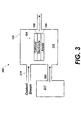
- FIG. 3 is a single chamber fuel cell system with a self-contained fuel supply that may be used with embodiments of the present invention.
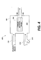
- FIG. 4 is a single chamber fuel cell system with a continuous fuel supply that may be used with embodiments of the present invention.
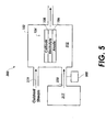
- FIG. 5 is a single chamber fuel cell system with a self-contained fuel supply and a gas sensor that may be used with embodiments of the present invention.
- odorant is used broadly to mean any substance detectable by a human sense of smell when it is released to atmosphere.
- An "odorant” may also indicate a substance readily detectable by a sensor.
- the odorant is detectable below a lower flammability limit of any fuel to which the odorant is added.
- fuel cell is also used broadly to mean any electrochemical cell in which the energy of a reaction between a fuel and an oxidant is converted directly into electrical energy. Therefore, the term “fuel cell” applies to at least all the types mentioned above in the background and other types known to those skilled in the art.
- the odorant used for leak detection in the fuel cell fuel supply may be chosen from a number of substances.
- the odorant includes organic molecules that can be added to the fuel supply of a fuel cell system at concentrations that are detectable to humans in the event of a fuel leak.
- a leak includes any loss of containment of the fuel in the fuel supply (other than a normal flow to the fuel cell), such as a leak to atmosphere.
- Aromatic compounds, furanones, and dienes are each discussed below in further detail.
- Aromatic compounds are known to have strong odors. These organic compounds have atoms of carbon, hydrogen, oxygen, and sometimes nitrogen. Each carbon atom typically includes one or more attached hydrogen atoms, and the hydrogen atoms may be consumed in the fuel cell reaction. Thus, aromatic compounds may function both as an odorant and as a source of energy for the fuel cell.
- Ketones are any of a class of organic compounds that contain the carbonyl group, and in which the carbonyl group is bonded only to carbon atoms.
- the general formula for a ketone is RCOR', where R and R' are alkyl or aryl groups.
- Ketones may be prepared by several methods, including the oxidation of secondary alcohols and the destructive distillation of certain salts of organic acids. Ketones are related to the aldehydes but are less active chemically. Ketones may be further subdivided into allylic and benzyllic ketones.
- Allylic and benzyllic ketones that may be especially useful for odorizing fuel cell fuel supplies may include, but are not limited to: beta-damascenone, 1-octen-3-one (amyl vinyl ketone), ionone (alpha-, beta-mixture), p-methylacetophenone, and citrus sinensis.
- Each of these ketones have a relatively low odor threshold (2x10 3 - 5x10 -3 ppb) and may be effectively used at low concentrations.
- the "odor threshold” is defined as the airborne concentration, usually in part per million (ppm) or parts per billion (ppb), at which an odor becomes noticeable.
- Other ketones such as acetone or other low molecular weight ketones have a much higher odor threshold.
- Acetone for example, has an odor threshold of 50,000 ppm. Odor thresholds for other organic compounds can be readily found by those of skill in the art having the benefit of this disclosure.
- Esters are defined as any one of a group of organic compounds with the general formula RCO 2 R' (where R and R' are alkyl groups or aryl groups) that are formed by the reaction between an alcohol and an acid. For example, when ethanol and acetic acid react, ethyl acetate (an ester) and water are formed. This particular reaction is called esterification.
- RCO 2 R' where R and R' are alkyl groups or aryl groups
- RCO 2 R' where R and R' are alkyl groups or aryl groups
- esters that may be used include, but are not limited to butyl acetate, Ethyl butyrate, Methyl butyrate, ethyl 2-methylbutyrate, etc. Esters offer an advantage over some of the other organic molecules mentioned herein by providing an odorant with a low fuel cell anode-coking tendency.
- furanones are another class of organic molecules that may be used according to principles described herein to odorize a fuel cell fuel supply.
- Furanones can be derived from compounds found in Australian seaweed or synthesized/modified by various routes.
- Furanones that may be useful as odorants include, but are not limited to: 5-ethyl-3-hydroxy-4-methyl-2(5H)-furanone, 3-hydroxy-4,5-dimethyl-2(5H)-furanone (Sotolon), and 2,5-dimethyl-4-methoxy-3(2H)-furanone.
- Each of these furanones has a low odor threshold.
- the odor threshold for 5-ethyl-3-hydroxy-4-methyl-2(5H)-furanone is on the order of 10 -4 ppb.
- the odor threshold for Sotolon is 10 -3 ppb.
- the odor threshold for 2,5-dimethyl-4-methoxy-3(2H)-furanone is 3x10 -2 ppb.
- Dienes are organic molecules which contain two carbon-carbon double bonds. Dienes may be used according to some aspects of the principles described herein to odorize fuel cell fuel supplies as well. Dienes that may be particularly useful as odorants include, but are not limited to: (E,Z)-2,6-nonadienal, cis-6-nonenal, and p-methylacetophenone.
- the odor threshold for each of these three dienes is, respectively, 10 -2 , 2x10 -2 , and 3x10 -2 ppb.
- the odorant added to the fuel cell fuel supply is organic and will not include sulfur, which is poisonous to most fuel cell anodes. However, there may be some instances where sulfur content in an odorant is tolerable. Further, it is preferable, although not mandatory, that the organic odorant have a relatively low (on the order of 10 ppb or less) odor threshold.
- the odorants described herein may be used for any fuel cell system, including systems using each of the fuel cell types mentioned in the background. Particular embodiments of fuel cell applications that may incorporate the odorants are described with reference to the figures below.
- the embodiments shown include portable fuel cell systems that include self-contained fuel supplies or cartridges, stationary fuel cell systems that are often connected to large storage tanks or pipelines that can provide a continuous flow, single chamber fuel cell systems, and dual chamber fuel cell systems.
- other fuel cell systems may also incorporate the principles descried herein, and the selected embodiments being described are only exemplary in nature.
- a housing (102) contains a single fuel cell (104).
- the fuel cell system (100) may include multiple fuel cells (104) arranged in a stack.
- the fuel cell (104) may be single fuel cell or a number of fuel cells operating as a unit.
- Each fuel cell (104) includes an anode (106), a cathode (108), and an electrolyte (110) sandwiched between the anode (106) and the cathode (108).
- the electrolyte (110) may include a solid oxide membrane, a polymer membrane, or other membrane used for other fuel cell types. It will be understood, however, that the fuel cell system (100) is not limited to the anode/electrolyte/cathode sandwich configuration shown. Other fuel cell systems, for example porous supports and current collector supported systems may also be used.
- the anode (106) and cathode (108) may include current collection layers and therefore also function as current collectors as the electrochemical reaction of the fuel cell takes place.
- Current generated by the fuel cell (104) may be directed to an external circuit to do useful work.
- the self-contained fuel supply (114) also includes one of the odorants described above.
- the odorant is added or injected into the self-contained fuel supply (114) as a leak indicator. It may be desirable, especially with portable fuel cell systems that may operate in confined spaces, to receive immediate notice of any fuel leaks. In the event of a leak, the odorant provides such notice to humans local to the fuel cell system (100). Accordingly, the odorant may be added to the self-contained fuel supply (114) before, after, or at the same time the fuel is added.
- a continuous fuel supply may also incorporate the principles described herein as shown in FIG. 2.
- a stationary fuel cell system (200) is shown with the same dual chamber design shown in FIG. 1.
- the stationary fuel cell system (200) is in fluid communication with a continuous supply of fuel via a supply line (214).
- the supply line (214) provides odorized fuel to the fuel cell (104).
- the fuel may be odorized in one or more ways described below.
- the odorant may also be added at a fuel production source, eliminating the need for the fitting (215). Further, it will be understood that the principles described herein may be applied to any fuel cell fuel source by adding an odorant, preferably an organic odorant.
- the self-contained fuel supply (317) of FIG. 3 may house any of a number of various fuels for supply to the anode (106) of the fuel cell (104). And in addition to containing a fuel, the self-contained fuel supply (317) also includes the one or more of the odorants described above. Accordingly, FIG. 3 illustrates that a single chamber fuel cell system may also be used with an odorant to facilitate leak detection according to the principles described herein.
- An oxidant stream (319) may also be coupled to the fuel cell housing (102) as shown to provide an oxidant to the cathode (108).
- the self-contained fuel supply (317) of FIG. 3 may optionally include an oxidant to create a gas mixture within the self-contained fuel supply (317) of fuel, odorant, and oxidant.
- the oxidant stream (319) would be omitted and the anode (106) may include materials that limit reaction to a fuel portion of the mixture or to fuel and odorant portions of the mixture, while the cathode (108) may include materials that will only react with the oxidant portion of the mixture.
- a continuous fuel supply coupled with a single chamber fuel cell system may also incorporate the principles described herein.
- a single chamber stationary fuel cell system (400) is in fluid communication with a continuous supply of fuel via the supply line (214) and oxidant via the oxidant stream (118). Similar or identical to the embodiment shown in FIG. 2, the supply line (214) provides odorized fuel to the fuel cell (104). The fuel may be odorized via the fitting (215) in the same ways described above with reference to the embodiments of FIGs. 1-2.
- odorants into fuel cell systems, particularly organic molecules that can also act as sources of fuel, provides a leak detection mechanism without the need for any specialized anodes that are sulfur-tolerant.
- organic molecules that may be advantageously used are wide and varied as discussed above.
- the present specification contemplates the use of any organic odorant for any fuel cell system to facilitate leak detection.
- the organic odorants may also be used in combination with a sensor (500) designed to sense the presence of specified organic compounds as shown in FIG. 5.
- the sensor (500) may be coupled to the fuel supply (317), the fuel cell housing (102), or some other component of the fuel cell system (300).
- the sensor (500) may be located in proximity to the self-contained fuel supply (300) (if there is one, other embodiments may not have a self-contained fuel supply), the fuel cell housing (102), or both, enabling the sensor (500) to quickly detect any leaks.
- the sensor (500) may also include circuitry programmed to shut down the fuel cell system (300) in the event of a detected leak.
- the addition of the sensor (500) may facilitate use of organic odorants at very low concentrations that are not detectable by humans. Furthermore, the organic odorant molecule can be chosen so that extremely high sensitivity and selectivity of the sensor is realized to avoid false alarms.
- An example of a sensor (500) for detecting organic molecules is available from Airsense Analytics in Germany or other sources.
Landscapes
- Chemical & Material Sciences (AREA)
- Engineering & Computer Science (AREA)
- General Chemical & Material Sciences (AREA)
- Chemical Kinetics & Catalysis (AREA)
- Sustainable Development (AREA)
- Sustainable Energy (AREA)
- Life Sciences & Earth Sciences (AREA)
- Electrochemistry (AREA)
- Manufacturing & Machinery (AREA)
- Oil, Petroleum & Natural Gas (AREA)
- Organic Chemistry (AREA)
- Fuel Cell (AREA)
- Examining Or Testing Airtightness (AREA)
Applications Claiming Priority (2)
| Application Number | Priority Date | Filing Date | Title |
|---|---|---|---|
| US10/405,144 US20040197919A1 (en) | 2003-04-01 | 2003-04-01 | Fuel cell leak detection |
| US405144 | 2003-04-01 |
Publications (2)
| Publication Number | Publication Date |
|---|---|
| EP1464693A2 true EP1464693A2 (de) | 2004-10-06 |
| EP1464693A3 EP1464693A3 (de) | 2006-03-01 |
Family
ID=32850609
Family Applications (1)
| Application Number | Title | Priority Date | Filing Date |
|---|---|---|---|
| EP04251993A Withdrawn EP1464693A3 (de) | 2003-04-01 | 2004-04-01 | Leckdetektion bei Brennstoffzellen |
Country Status (6)
| Country | Link |
|---|---|
| US (2) | US20040197919A1 (de) |
| EP (1) | EP1464693A3 (de) |
| JP (1) | JP3999756B2 (de) |
| KR (1) | KR20040088389A (de) |
| CA (1) | CA2448422A1 (de) |
| TW (1) | TW200421665A (de) |
Cited By (3)
| Publication number | Priority date | Publication date | Assignee | Title |
|---|---|---|---|---|
| WO2006067112A1 (en) * | 2004-12-22 | 2006-06-29 | Symrise Gmbh & Co. Kg | Odorant for hydrogen based on acrylate and acetophenone |
| EP1935844A4 (de) * | 2005-09-07 | 2009-09-16 | Toyota Motor Co Ltd | Wasserstoffzufuhrvorrichtung und brennstoffgaszufuhrvorrichtung |
| EP2672818A1 (de) * | 2011-02-10 | 2013-12-18 | Schalk Francois Mouton | Rüsselkäfer-lockmittel |
Families Citing this family (23)
| Publication number | Priority date | Publication date | Assignee | Title |
|---|---|---|---|---|
| US20040031314A1 (en) * | 2002-08-13 | 2004-02-19 | Patrick Flynn | Hydrogen odorants and odorant selection method |
| US20050079620A1 (en) * | 2003-10-10 | 2005-04-14 | Eberhard Douglas P. | Leak testing of hermetic enclosures for implantable energy storage devices |
| JP4709518B2 (ja) * | 2004-09-29 | 2011-06-22 | 株式会社東芝 | プロトン伝導膜及び燃料電池 |
| JP2006196415A (ja) * | 2005-01-17 | 2006-07-27 | Hitachi Ltd | 燃料電池検査システム |
| JP2007078591A (ja) * | 2005-09-15 | 2007-03-29 | Toshiba Corp | 漏洩検知構造および燃料カートリッジ |
| JP5270076B2 (ja) | 2006-07-20 | 2013-08-21 | トヨタ自動車株式会社 | 車載水素貯蔵装置 |
| JP5082759B2 (ja) * | 2007-10-23 | 2012-11-28 | トヨタ自動車株式会社 | 燃料電池システム |
| US7915047B2 (en) | 2007-11-19 | 2011-03-29 | Los Alamos National Security, Llc | Coating for leak detection and method |
| WO2009143327A1 (en) * | 2008-05-21 | 2009-11-26 | Enersol, Inc.., N.A. L.P. | Hydrogen odorization |
| WO2010120309A1 (en) * | 2009-04-17 | 2010-10-21 | Utc Power Corporation | Fuel cell stack gas leak detection |
| CN103512712B (zh) * | 2012-06-29 | 2016-02-10 | 新普科技股份有限公司 | 电池品质检测装置与方法 |
| CN111829737B (zh) * | 2019-04-18 | 2023-01-06 | 中国科学院宁波材料技术与工程研究所 | 一种固体氧化物燃料电池的气密性检测方法 |
| US12377711B2 (en) | 2020-08-20 | 2025-08-05 | Denso International America, Inc. | Vehicle feature control systems and methods based on smoking |
| US11932080B2 (en) | 2020-08-20 | 2024-03-19 | Denso International America, Inc. | Diagnostic and recirculation control systems and methods |
| US11828210B2 (en) | 2020-08-20 | 2023-11-28 | Denso International America, Inc. | Diagnostic systems and methods of vehicles using olfaction |
| US11760170B2 (en) | 2020-08-20 | 2023-09-19 | Denso International America, Inc. | Olfaction sensor preservation systems and methods |
| US11881093B2 (en) | 2020-08-20 | 2024-01-23 | Denso International America, Inc. | Systems and methods for identifying smoking in vehicles |
| US11760169B2 (en) | 2020-08-20 | 2023-09-19 | Denso International America, Inc. | Particulate control systems and methods for olfaction sensors |
| US12269315B2 (en) | 2020-08-20 | 2025-04-08 | Denso International America, Inc. | Systems and methods for measuring and managing odor brought into rental vehicles |
| US11813926B2 (en) | 2020-08-20 | 2023-11-14 | Denso International America, Inc. | Binding agent and olfaction sensor |
| US12251991B2 (en) | 2020-08-20 | 2025-03-18 | Denso International America, Inc. | Humidity control for olfaction sensors |
| US11636870B2 (en) | 2020-08-20 | 2023-04-25 | Denso International America, Inc. | Smoking cessation systems and methods |
| US12017506B2 (en) | 2020-08-20 | 2024-06-25 | Denso International America, Inc. | Passenger cabin air control systems and methods |
Family Cites Families (16)
| Publication number | Priority date | Publication date | Assignee | Title |
|---|---|---|---|---|
| US4007755A (en) * | 1974-01-18 | 1977-02-15 | Sun Oil Company Of Pennsylvania | Component injection system |
| US6156084A (en) * | 1998-06-24 | 2000-12-05 | International Fuel Cells, Llc | System for desulfurizing a fuel for use in a fuel cell power plant |
| JP2000233901A (ja) * | 1999-02-10 | 2000-08-29 | Sanyo Electric Co Ltd | 水素製造装置および燃料電池システムならびにこれらの運転方法 |
| JP2002083623A (ja) * | 2000-06-27 | 2002-03-22 | Idemitsu Kosan Co Ltd | 燃料電池設備、その燃料および燃料供給装置 |
| JP2002029701A (ja) * | 2000-07-10 | 2002-01-29 | Toyota Motor Corp | 水素供給装置および該水素供給装置を備える燃料電池装置、並びに水素検出方法 |
| JP2002060766A (ja) * | 2000-08-17 | 2002-02-26 | Nippon Mitsubishi Oil Corp | 燃料電池用燃料付臭剤 |
| US7201783B2 (en) * | 2000-11-13 | 2007-04-10 | Idatech, Llc | Fuel processing system and improved feedstock therefor |
| DE10058805A1 (de) * | 2000-11-27 | 2002-06-06 | Ticona Gmbh | Odoriermittel für Gase |
| EP1283557A1 (de) * | 2001-08-01 | 2003-02-12 | Siemens Aktiengesellschaft | Verfahren zum Lokalisieren eines Gaslecks innerhalb einer Brennstoffzellenanordnung |
| JP2003138280A (ja) * | 2001-10-31 | 2003-05-14 | Ogawa & Co Ltd | 無臭ガス用付臭剤 |
| JP3836357B2 (ja) * | 2001-11-21 | 2006-10-25 | 東京瓦斯株式会社 | 燃料電池の燃料水素用付臭剤 |
| AU2002349459A1 (en) * | 2001-11-22 | 2003-06-10 | Soda Aromatic Co., Ltd. | Odorant for fuel gas |
| JP2003201487A (ja) * | 2002-01-10 | 2003-07-18 | Toyota Motor Corp | 燃料電池用燃料ガス |
| US20040031314A1 (en) * | 2002-08-13 | 2004-02-19 | Patrick Flynn | Hydrogen odorants and odorant selection method |
| JP4023731B2 (ja) * | 2002-09-18 | 2007-12-19 | 本田技研工業株式会社 | 水素供給装置 |
| US7024869B2 (en) * | 2002-12-16 | 2006-04-11 | Air Products And Chemicals, Inc. | Addition of odorants to hydrogen by incorporating odorants with hydrogen storage materials |
-
2003
- 2003-04-01 US US10/405,144 patent/US20040197919A1/en not_active Abandoned
- 2003-09-29 TW TW092126861A patent/TW200421665A/zh unknown
- 2003-11-05 CA CA002448422A patent/CA2448422A1/en not_active Abandoned
-
2004
- 2004-03-30 JP JP2004099620A patent/JP3999756B2/ja not_active Expired - Fee Related
- 2004-04-01 EP EP04251993A patent/EP1464693A3/de not_active Withdrawn
- 2004-04-01 KR KR1020040022503A patent/KR20040088389A/ko not_active Withdrawn
-
2006
- 2006-05-22 US US11/438,190 patent/US20060211119A1/en not_active Abandoned
Cited By (6)
| Publication number | Priority date | Publication date | Assignee | Title |
|---|---|---|---|---|
| WO2006067112A1 (en) * | 2004-12-22 | 2006-06-29 | Symrise Gmbh & Co. Kg | Odorant for hydrogen based on acrylate and acetophenone |
| US8545724B2 (en) | 2004-12-22 | 2013-10-01 | Symrise Ag | Odorant for hydrogen based on acrylate and acetophenone |
| EP1935844A4 (de) * | 2005-09-07 | 2009-09-16 | Toyota Motor Co Ltd | Wasserstoffzufuhrvorrichtung und brennstoffgaszufuhrvorrichtung |
| US8746274B2 (en) | 2005-09-07 | 2014-06-10 | Toyota Jidosha Kabushiki Kaisha | Hydrogen supply apparatus and fuel gas supply apparatus |
| EP2672818A1 (de) * | 2011-02-10 | 2013-12-18 | Schalk Francois Mouton | Rüsselkäfer-lockmittel |
| EP2672818A4 (de) * | 2011-02-10 | 2014-08-27 | Schalk Francois Mouton | Rüsselkäfer-lockmittel |
Also Published As
| Publication number | Publication date |
|---|---|
| EP1464693A3 (de) | 2006-03-01 |
| KR20040088389A (ko) | 2004-10-16 |
| JP2004311436A (ja) | 2004-11-04 |
| US20060211119A1 (en) | 2006-09-21 |
| CA2448422A1 (en) | 2004-10-01 |
| JP3999756B2 (ja) | 2007-10-31 |
| TW200421665A (en) | 2004-10-16 |
| US20040197919A1 (en) | 2004-10-07 |
Similar Documents
| Publication | Publication Date | Title |
|---|---|---|
| EP1464693A2 (de) | Leckdetektion bei Brennstoffzellen | |
| JP4202109B2 (ja) | 燃料電池システム | |
| Varcoe et al. | Investigations into the ex situ methanol, ethanol and ethylene glycol permeabilities of alkaline polymer electrolyte membranes | |
| US8039154B2 (en) | Fuel cell system, method of starting fuel cell system | |
| Tran et al. | A fuel‐flexible alkaline direct liquid fuel cell | |
| JP4334578B2 (ja) | 燃料電池システム | |
| Gong et al. | Direct conversion of wheat straw into electricity with a biomass flow fuel cell mediated by two redox ion pairs | |
| US8354043B2 (en) | Natural gas odorization | |
| Mardle et al. | Performance and Stability of Aemion and Aemion+ Membranes in Zero‐Gap CO2 Electrolyzers with Mild Anolyte Solutions | |
| US8765314B2 (en) | Fuel cell system and method for stopping operation of fuel cell system | |
| JP2006523935A (ja) | 燃料容器から燃料を除去/酸化分解するためのシステム及び方法 | |
| JP2005535072A (ja) | 劣化防護されたアノードを有する燃料電池システム | |
| JP4872181B2 (ja) | 燃料電池システムとその運転方法 | |
| CN117751210A (zh) | 二氧化碳回收系统 | |
| US8637207B2 (en) | Liquid fuel, fuel cartridge and fuel cell | |
| JP2006253046A (ja) | 液体燃料電池システム及びその運転方法 | |
| JP2005071778A (ja) | 燃料電池システムとその運転方法 | |
| JP2007194157A (ja) | 燃料電池システム | |
| KR20180091315A (ko) | 연료전지 시스템 | |
| JPWO2006134975A1 (ja) | 燃料電池用燃料、燃料電池用燃料カートリッジ及び燃料電池 | |
| CN109565062A (zh) | 用于关停具有燃料电池装置的发电机系统的方法 | |
| Zhai et al. | Acetylene contamination mechanisms in the cathode of proton exchange membrane fuel cells | |
| CN101142702A (zh) | 液体燃料、燃料盒及燃料电池 | |
| WO2014045510A1 (ja) | 直接酸化型燃料電池システムおよびこれに用いる回収タンク | |
| JP2006331907A (ja) | 直接メタノール型燃料電池 |
Legal Events
| Date | Code | Title | Description |
|---|---|---|---|
| PUAI | Public reference made under article 153(3) epc to a published international application that has entered the european phase |
Free format text: ORIGINAL CODE: 0009012 |
|
| AK | Designated contracting states |
Kind code of ref document: A2 Designated state(s): AT BE BG CH CY CZ DE DK EE ES FI FR GB GR HU IE IT LI LU MC NL PL PT RO SE SI SK TR |
|
| AX | Request for extension of the european patent |
Extension state: AL HR LT LV MK |
|
| PUAL | Search report despatched |
Free format text: ORIGINAL CODE: 0009013 |
|
| AK | Designated contracting states |
Kind code of ref document: A3 Designated state(s): AT BE BG CH CY CZ DE DK EE ES FI FR GB GR HU IE IT LI LU MC NL PL PT RO SE SI SK TR |
|
| AX | Request for extension of the european patent |
Extension state: AL HR LT LV MK |
|
| RIC1 | Information provided on ipc code assigned before grant |
Ipc: G01M 3/20 20060101ALI20060111BHEP Ipc: H01M 8/04 20060101ALI20060111BHEP Ipc: C10L 3/00 20060101AFI20040816BHEP |
|
| 17P | Request for examination filed |
Effective date: 20060814 |
|
| AKX | Designation fees paid |
Designated state(s): FR |
|
| REG | Reference to a national code |
Ref country code: DE Ref legal event code: 8566 |
|
| 17Q | First examination report despatched |
Effective date: 20061214 |
|
| STAA | Information on the status of an ep patent application or granted ep patent |
Free format text: STATUS: THE APPLICATION IS DEEMED TO BE WITHDRAWN |
|
| 18D | Application deemed to be withdrawn |
Effective date: 20091103 |