EP1450107A1 - "faltbares, wärme abstrahlendes flächengebilde" - Google Patents
"faltbares, wärme abstrahlendes flächengebilde" Download PDFInfo
- Publication number
- EP1450107A1 EP1450107A1 EP02783646A EP02783646A EP1450107A1 EP 1450107 A1 EP1450107 A1 EP 1450107A1 EP 02783646 A EP02783646 A EP 02783646A EP 02783646 A EP02783646 A EP 02783646A EP 1450107 A1 EP1450107 A1 EP 1450107A1
- Authority
- EP
- European Patent Office
- Prior art keywords
- heat radiation
- members
- fluid tube
- plate
- portions
- Prior art date
- Legal status (The legal status is an assumption and is not a legal conclusion. Google has not performed a legal analysis and makes no representation as to the accuracy of the status listed.)
- Withdrawn
Links
Images


Classifications
-
- F—MECHANICAL ENGINEERING; LIGHTING; HEATING; WEAPONS; BLASTING
- F24—HEATING; RANGES; VENTILATING
- F24D—DOMESTIC- OR SPACE-HEATING SYSTEMS, e.g. CENTRAL HEATING SYSTEMS; DOMESTIC HOT-WATER SUPPLY SYSTEMS; ELEMENTS OR COMPONENTS THEREFOR
- F24D3/00—Hot-water central heating systems
- F24D3/12—Tube and panel arrangements for ceiling, wall, or underfloor heating
- F24D3/16—Tube and panel arrangements for ceiling, wall, or underfloor heating mounted on, or adjacent to, a ceiling, wall or floor
-
- E—FIXED CONSTRUCTIONS
- E04—BUILDING
- E04C—STRUCTURAL ELEMENTS; BUILDING MATERIALS
- E04C2/00—Building elements of relatively thin form for the construction of parts of buildings, e.g. sheet materials, slabs, or panels
- E04C2/44—Building elements of relatively thin form for the construction of parts of buildings, e.g. sheet materials, slabs, or panels characterised by the purpose
- E04C2/52—Building elements of relatively thin form for the construction of parts of buildings, e.g. sheet materials, slabs, or panels characterised by the purpose with special adaptations for auxiliary purposes, e.g. serving for locating conduits
-
- Y—GENERAL TAGGING OF NEW TECHNOLOGICAL DEVELOPMENTS; GENERAL TAGGING OF CROSS-SECTIONAL TECHNOLOGIES SPANNING OVER SEVERAL SECTIONS OF THE IPC; TECHNICAL SUBJECTS COVERED BY FORMER USPC CROSS-REFERENCE ART COLLECTIONS [XRACs] AND DIGESTS
- Y02—TECHNOLOGIES OR APPLICATIONS FOR MITIGATION OR ADAPTATION AGAINST CLIMATE CHANGE
- Y02B—CLIMATE CHANGE MITIGATION TECHNOLOGIES RELATED TO BUILDINGS, e.g. HOUSING, HOUSE APPLIANCES OR RELATED END-USER APPLICATIONS
- Y02B30/00—Energy efficient heating, ventilation or air conditioning [HVAC]
Definitions
- the present invention relates to a foldable heat radiation board, and in particular, to a foldable heat radiation board which is installed on the surface of a base material of a building, such as an ordinary housing, a condominium, a commercial building, or hotel; which is applicable to a wall surface, a ceiling board, a screen, or the like of a residential space; which is capable of being folded; and which is facilitated in packaging, storage, transportation, installation and other operations, whereby a flat-finished surface can be obtained after the completion of installation.
- a base material of a building such as an ordinary housing, a condominium, a commercial building, or hotel
- a floor heating technology for heating inside of a house from the floor has conventionally been proposed and put into practical use.
- a technology with which, for instance, a heat radiation board (also called the "panel") for floor heating is incorporated between a sleeper and a floor board or on the upper surface (or on the upper side) of a backing plywood laid on the sleeper and heating is performed using the heat radiation board.
- a heat radiation board for floor heating is laid directly on the upper surface of a floor slab or on a backing plywood laid on the upper surface of the floor slab.
- JP 60-223922 A, JP 03-175216 A, JP 04-80596 A, JP 08-261485 A, and the like there are proposed heat radiation boards for floor heating having a structure where grooves or spaces are formed in one surface of each plate-like member made of a soft foam or a hard foam, fluid tubes (heat carrier flexible tubes) are embedded in the grooves or the spaces, and the surfaces of the tubes are covered with a heat equalizer material such as an aluminum foil.
- a heat equalizer material such as an aluminum foil.
- these heat radiation boards panels that have conventionally been known are obtained by forming grooves or spaces in elongated and narrow plate-shape members along the lengthwise direction of the plate-like members and embedding fluid tubes, through which a fluid is to be allowed to flow, in the grooves or the spaces.
- a heat radiation board having this structure there is generally adopted a technology with which a wide heat radiation board is assembled in advance at a place other than the installation site and then is brought to the installation site to be installed.
- the heat radiation board having the proposed structure still suffers from problems in that the manufacturing process is complicated because the number of plate-like members is increased, the installation is also complicated because it is required to conduct the installation while fitting the fluid tubes in the grooves provided in the plate-like members, and the surface of the heat radiation board after the installation is uneven although a flat surface is desired.
- the present invention provides a heat radiation board, in which the number of construction elements (components) is reduced, the manufacturing process is not complicated, folding is possible, there hardly occur buckling of fluid tubes and damage due to friction with grooves formed in plate-like members at the time of packaging, storage, transportation, and installation, the installation at the installation site is facilitated, and a surface after the installation has a flat finish.
- a foldable heat radiation board in which a plurality of elongated and narrow plate-like members with fluid tube embedding grooves provided in one surface thereof are arranged in an approximately quadrangular plan configuration in which end portions thereof contact with each other, fluid tubes are embedded in the embedding grooves, a heat radiation sheet is attached to an entire surface on a front surface side, a back surface material is attached to at least a part of a surface on a back surface side, a plurality of folding portions are formed by a plurality of contact portions in which end portions of adjacent plate-like members contact with each other, the foldable heat radiation board being characterized in that:
- FIG. 1 is a partial schematic plan view of an example of a foldable heat radiation board according to the present invention.
- FIG. 2 is an enlarged schematic plan view of portion I shown in FIG. 1.
- FIG. 3 is an enlarged schematic plan view of portion II (tube passage portion) shown in FIG. 2.
- FIG. 4 is a schematic vertical side view taken along the line III-III of FIG. 3, with a back surface material of the heat radiation board functioning as a hinge.
- FIG. 5 is a schematic vertical side view corresponding to FIG. 4 , with a heat radiation sheet of the heat radiation board functioning as a hinge.
- FIG. 6 is an enlarged schematic plan view of a state where a deep cutout portion is provided in the portion II (tube passage portion) shown in FIG. 2.
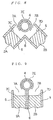
- FIG. 7 is a schematic vertical side view taken along the line IV-IV of FIG. 6, with the back surface material of the heat radiation board functioning as a hinge.
- FIG. 8 is a schematic vertical side view of a state where the heat radiation board is in the course of being folded using the back surface material as a hinge.
- FIG. 9 is a schematic vertical side view of a state where the folding from the state in FIG. 8 is finished.
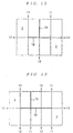
- FIG. 10 is a schematic plan view of an example of a foldable heat radiation board including four plate-like members.
- FIG. 11 is a schematic plan view of an example of a foldable heat radiation board including six plate-like members.
- FIG. 12 is a schematic plan view of an example of a foldable heat radiation board including eight plate-like members.
- FIG. 13 is a schematic plan view of an example of a foldable heat radiation board including ten plate-like members.
- a foldable heat radiation board (panel) according to the present invention is formed by combining a plurality of elongated and narrow plate-like members with each other so as to obtain a wide and elongated approximately quadrangular configuration after being installed, and is used to form a floor for floor heating, a wall surface, a ceiling board, a screen, or the like. Further, when a coolant is allowed to flow through fluid tubes of the heat radiation board instead of a heat carrier, the heat radiation board functions as a heat radiation board for cooling.
- the material of the plate-like members is selected from among a wooden flooring material, a wooden board, a plywood, a particle board, a fiber board, a synthetic resin board, and the like.
- the synthetic resin board it is suitable that the board is selected from among flat boards made of a hard foam resin having independent air bubbles and superior stiffness.
- the hard foam resin material include a polystyrene foam, a mixture of a polystyrene foam and a polyethylene foam, a polypropylene foam, hard polyurethane, foam hard rubber, and the like.
- the hard foam resin material is not limited to those of the examples.
- the expansion ratio of the synthesis resin board varies depending on the kind of resin used, but it is usually possible to select the expansion ratio in a range of 1.2 to 50 times, or preferably in a range of 2 to 30 times.
- the minimum thickness of the plate-like members is equal to the diameter of the fluid tubes, while the maximum thickness thereof may be selected in a range of up to a size obtained by adding 25 mm to the diameter of the fluid tubes. It is not preferable that the thickness of the plate-like members exceeds the size obtained by adding 25 mm to the diameter of the fluid tubes because the plate-like members become too thick and the heat radiation board becomes bulky as a whole, causing difficulty in handling thereof. It is usually possible to select the length of the plate-like members in a range of 60 to 400 cm in accordance with the installation site of the heat radiation board. When the heat radiation board is to be installed in a place having a large area, it is also possible to perform the installation by combining a plurality of heat radiation boards.
- the width of the plate-like members it is usually possible to select the width of the plate-like members in a range of 10 to 100 cm. If the width exceeds 100 cm, there is impaired workability at the time of folding, packaging, storage, transportation, and the like. On the other hand, if the width is less than 10 cm, there are such drawbacks as follows: it becomes impossible to form U-shaped grooves for changing the extending directions of the fluid tubes; many plate-like members become necessary to obtain a certain width, and processing, such as manufacturing of the heat radiation board, folding after the manufacturing, and installation by unfolding the board, become complicated. As a result, it is not preferable that the width of the plate-like members is set outside of the range described above. When the plurality of plate-like members are arranged to obtain a heat radiation board whose plan configuration is approximately quadrangular, it is preferable that the plurality of plate-like members have the same thickness, length, width, and the like.
- embedding grooves in which fluid tubes are to be embedded. It does not matter whether the embedding grooves are provided on the front surface side or the back surface side, but it is suitable that these grooves are provided on the front surface side from the viewpoint of heat radiation efficiency. It is preferable that the sectional configuration of these embedding grooves taken perpendicular to the extending direction thereof is U-shaped. It is also preferable that the opening width and depth of the embedding grooves, whose sectional configuration is U-shaped, are set approximately equal to the diameter of the fluid tubes. These embedding grooves are provided continuously by appropriately combining and connecting various grooves whose plan configurations are U-shaped, linear, and S-shaped (or inverse S-shaped).
- a heat radiation board having a structure where embedding grooves are provided on the front surface side of plate-like members.
- Embedding grooves having the U-shaped plan configuration are provided at one end both ends in the lengthwise direction of the plate-like members and change the extending directions of fluid tubes while maintaining their embedded state.
- embedding grooves having the linear plan configuration are provided along the lengthwise direction of the plate-like members to establish connection between the U-shaped grooves in the end portions.
- embedding grooves having the S-shaped (or inverse S-shaped) plan configuration are provided in portions in which some of the plurality of folding portions of the fluid tubes extend from one to the other of adjacent plate-like members.
- the radius of the curvature of the U-shaped grooves and the S-shaped (inverse S-shaped) grooves is set at a minimum size with which the fluid tubes will never be buckled. It is also preferable that the embedding grooves are distributed so that heat is radiated uniformly from the entire surface of the heat radiation board or is radiated uniformly from a given portion in which heating is desired.
- the heat radiation board according to the present invention has a construction where the position of a fluid tube outlet opening portion (fluid flowing-out portion) in the end portion of one of adjacent plate-like members and the position of a fluid tube inlet opening portion (fluid flowing-in portion) in the end portion of the other of the plate-like members are set so that these opening portions do not oppose each other but are shifted from each other (this will be describe later, see FIGS. 3 and 6).
- a fluid tube is arranged so as to extend through a portion between the outlet of one of adjacent plate-like members and the inlet of the other thereof (this portion will be hereinafter sometimes referred to as the "tube passage portion") , so that when the heat radiation board is folded at each folding portion including the tube passage portion, the fluid tube is placed in a linear state and is exposed to the outside in this tube passage portion, which reduces the degree of twist occurring in the fluid tube and prevents the fluid tube from being bent at a right angle. As a result, buckling hardly occurs in the fluid tube.
- the length by which the positions of the opening portions are shifted from each other is set too short, the degree of twist in the fluid tube is increased and the fluid tube is bent at an angle close to a right angle, so that the buckling easily occurs.
- the length is too long, when a folding state is reset to a plane state, it is difficult to fit the fluid tube exposed at in this portion in a fluid tube arrangement cutout portion , and neither of these cases is preferable. It is preferable that the length, by which the positions are shifted from each other, is set as five to 20 times the diameter of the fluid tube.
- the fluid tube arrangement cutout portion is provided between the opening portions described above (in the tube passage portion) on the wall surfaces in the end portions of the adjacent plate-like members.
- This fluid tube arrangement cutout portion is provided so as to be mirror-symmetric in the end portions of the two plate-like members, thereby obtaining a structure where when the wall surfaces in the end portions of the two plate-like members are brought into contact with each other, an embedding groove having a U-shaped sectional configuration is formed (this will be described later, see FIGS. 4 and 5 and the like) .
- Such a tube passage portion is provided, so that when the heat radiation board is folded at a contact portion in which the end portions of the plate-like members contact with each other, the fluid tube passing through the tube passage portion is exposed and, when the folding state is reset and the heat radiation board is set in a plane state, it is possible to fit the fluid tube in the fluid tube arrangement cutout portion provided in the tube passage portion with ease. It does not matter whether the length of the fluid tube arrangement cutout portion is equal to the length of the tube passage portion or is equal to the entire length of the folding portion including the tube passage portion.
- the location, at which the folding portion including the fluid tube passage portion is provided for the heat radiation board may be any of (1) only in the end portions in the widthwise direction of the plate-like members, (2) only in the end portions in the lengthwise direction of the plate-like members, and (3) in both of the end portions in the widthwise direction and the end portions in the lengthwise direction.
- the location (1) is adopted when a wide heat radiation board is obtained by combining the plurality of elongated and narrow plate-like members.
- the location (2) is adopted when an elongated heat radiation board is obtained by combining the plurality of elongated and narrow plate-like members
- the location (3) is adopted when a wide and elongated heat radiation board is obtained by combining the plurality of elongated and narrow plate-like members.
- a fluid tube retainer is provided at an appropriate position on the surface of each fluid tube.
- the fluid tube retainer is attached at a position on the surface of the fluid tube corresponding to a portion in which a deep cutout portion is provided.
- the sectional configuration of the fluid tube retainer taken perpendicular to the lengthwise direction of the fluid tube is like a short C-shaped tube.
- the fluid tube retainer is made of a relatively hard material, such as cross-linked polyethylene, polybutene, polypropylene, or semi-hard polyvinyl chloride, and the thickness and length (width) of the fluid tube retainer are respectively selected in a range of 1.0 to 5 mm and in a range of 3 to 20 mm.
- a deep cutout portion that is deeper than the fluid tube arrangement cutout portion is provided so as to be adjacent to the inlet opening portion and the outlet opening portion of the fluid tube arrangement cutout portion.
- the sectional configuration of the deep cutout portion taken in the lengthwise direction is U-shaped, the depth thereof is set equal to or somewhat larger than a depth with which fitting is possible under a state where the fluid tube retainer is attached to the surface of the fluid tube, and the length (width) of the deep cutout portion is set equal to or somewhat larger than the length of the fluid tube retainer.
- the fluid tubes arranged and embedded in the grooves achieve a function of allowing a heat carrier or a coolant to pass through inner spaces thereof and are required to excel in flexibility as well as mechanical strength, heat resistance, chemical resistance, and the like.
- Examples of tube having such properties include a cross-linked polyethylene tube, a polybutene tube, a polypropylene tube, a soft polyvinyl chloride tube, a nylon tube, and these resin tubes in whose wall surfaces there are embedded metal wires. Of these, the cross-linked polyethylene tube and the polybutene tube are preferable.
- the cuter diameter of the heat carrier tubes varies depending on the district in which a building is constructed, the kind of the building, and the like, although it is possible to select the outer diameter in a range of 3 to 20 mm. Also, it is possible to select the thickness thereof in a range of 0.5 to 5 mm.
- Examples of the media allowed to flow through the fluid tubes include water, ethylene glycol, propylene glycol, a gas, and the like regardless of whether the media is used as a heat carrier or a coolant.
- the fluid tubes are connected to a fluid circulating apparatus provided with a fluid temperature adjusting apparatus through a fluid header. It is preferable that the fluid temperature adjusting apparatus is placed in the vicinity of the installation site of the heat radiation board, such as the underfloor, the outside, or the rooftop of a building.
- a heat radiation sheet is attached to the entire surface on the front surface side and a back surface material is attached to the entire or partial surface on the back surface side.
- the heat radiation sheet is attached to the entire surface on the front surface side of the heat radiation board, although the back surface material is attached to the entire or partial surface on the back surface side of the heat radiation board.
- either the heat radiation sheet or the back surface material is made discontinuous along the plurality of folding portions.
- the word “continuous” refers to a state where the sheet or the material is not cut at the folding portions, while the word “discontinuous” refers to a state where the sheet or the material is cut at the folding portions.
- the heat radiation sheet connecting the heat radiation board functions as a hinge and there is obtained a structure (hereinafter referred to as the "valley-foldable structure") where the heat radiation board is capable of being folded in a valley shape.
- the back surface material on the back surface side of the heat radiation board is made continuous at the folding portions and the heat radiation sheet on the front surface side is made discontinuous at the folding portions
- the back surface material connecting the heat radiation board functions as a hinge and there is obtained a structure (hereinafter referred to as the "mountain-foldable structure") where the heat radiation board is capable of being folded in a mountain shape.
- the back surface material is attached so as to achieve the function of a hinge, which means that it is not required to attach the back surface material to the entire surface in the lengthwise direction of the folding portion and the back surface material may be partially attached to the folding portion at constant intervals.
- the heat radiation sheet or the back surface material may be made discontinuous by cutting along the folding portions using a knife or the like.
- both of the heat radiation sheet and the back surface material are made discontinuous at some of the plurality of folding portions (this will be described later, see FIGS. 10 to 13) .
- both of the heat radiation sheet and the back surface material are made discontinuous at some of the plurality of folding portions.
- the folding portions, in which both of the heat radiation sheet and the back surface material are made discontinuous may be determined as appropriate in accordance with the number of plate-like members constituting the heat radiation board (this will be described later, see FIGS. 10 to 13). Even when the plurality of plate-like members are arranged to form two rows (or two columns) , it is possible to perform folding smoothly by making both of the heat radiation sheet and the back surface material discontinuous at some of the plurality of folding portions.
- this heat radiation sheet prevents the fluid tubes embedded in the embedding grooves from detaching from the embedding grooves and functions as a hinge at the folding portions, as described above.
- this heat radiation sheet pushes the fluid tubes into the fluid tube arrangement cutoutportions.
- the heat radiation sheet include an aluminum foil, a metal foil plate, a metal plate, a lamination body of an aluminum foil and a nonwoven fabric, a material obtained by evaporating a metal, such as aluminum, onto a plastic film, or a lamination member thereof.
- examples of the back surface material include an aluminum foil, a plastic film, a nonwoven fabric, a lamination body of an aluminum foil and a nonwoven fabric, and the like.
- the thickness of the heat radiation sheet is selected in a range of 0.5 to 3 mm in the case of a hard plate-like material and is selected in a range of 10 im to 0.3 mm in the case of a material with superior flexibility.
- the heat radiation board according to the present invention has a structure where the fluid tube retainers are attached to the fluid tubes, it is preferable that the whole of the heat radiation sheet or a part thereof in the vicinity of each folding portion is made of a hard plate-like material.
- a hard plate-like material is used and the mountain-foldable structure is obtained, the hard plate-like member contacts the surface of the fluid tube retainer prior to the surface of the fluid tube and the fluid tube retainer is pushed into the deep cutout portion in the course of an operation where the folding state is reset to a plane state at the time of installation of the heat radiation board. In this process, the fluid tube is simultaneously pushed into the fluid tube arrangement cutout portion, so that it becomes possible to prevent the fluid tube from protruding from the fluid tube passage portion.
- the thickness of the plate-like members is made thin as much as possible and the heat radiation sheet attached to the back surface side is regarded as a back surface material.
- This back surface material has a function of preventing the fluid tubes from being detached from the embedding grooves and also has a function of reflecting heat to the front surface side of the plate-like members, so that it is preferable that the back surface material is attached to the entire surface on the back surface side.
- a technology of combining the plurality of plate-like members with each other, a technology of embedding fluid tubes, a technology of forming folding portions, and the like used in this case are the same as those used in the aforementioned case where the embedding grooves are provided on the front surface side of the plate-like members.
- the foldable heat radiation board according to the present invention is manufactured in advance in a plant, a factory, or the like that is different from the installation site.
- the heat radiation board is produced to have a desired wide area by arranging the plurality of plate-like members so that the end portions thereof contact with each other, and has a plane configuration that is approximately quadrangular.
- Continuousfluid tubes are embedded in the fluid tube embedding grooves provided on one surface, a heat radiation sheet is attached to the entire surface on the front surface side, a back surface material is attached to the entire or partial surface on the back surface side, and the heat radiation sheet and/or the back surface material are/is made discontinuous at the folding portions by cutting.
- the heat radiation sheet and/or the back surface material in the folding portions are/is made discontinuous as described above, so that the discontinuous surface side is opened using the continuous surface side as a hinge at the time of folding (this will be described later, see FIG. 8).
- the foldable heat radiation board After being manufactured at a place that is different from the installation site, the foldable heat radiation board is transported/transferred to the installation site in a building under a folded state.
- the board is unfolded to be installed at a predetermined position on the backing surface of a building floor.
- the building may be an already-existing one as well as a newly constructed one.
- the backing surface refers to a slab surface or a backing floor plywood disposed thereon.
- the backing surface refers to a backing floor plywood.
- the predetermined position may be the whole or a specific part of the floor of a room.
- the plurality of heat radiation boards may be combined with each other. It is possible to fix the heat radiation board to the backing surface or an already-existing floor made of a backing floor plywood using screws or nails.
- a decorative material is arranged on the heat radiation sheet.
- the decorative material include a plywood, a wooden board, a fiber board, a resin board, a particle board, a carpet, and the like, although the present invention is not limited to these examples.
- the decorative material is selected in accordance with the kind of material of the plate-like members. It does not matter whether the decorative material is formed by a single wide material or the plurality of thin and small material pieces combined with each other. It is possible to apply a coating to the surface of the decorative material or to print a wood-grain pattern or another pattern thereon. Usually, it is possible to select the thickness of the decorative material in a range of 1 mm to 15 mm . If the thickness is too thin, the functions described above cannot be attained. On the other hand, if the thickness is too thick, the heat transfer efficiency from the fluid tubes is lowered, and, therefore neither of these cases is preferable.
- the foldable heat radiation board according to the present invention is used as a wall surface material, a ceiling material, or the like, it is possible to execute construction work by following the aforementioned method of constructing the heating floor.
- a reinforcement board is attached to its back surface to thereby obtain a certain width with which there is obtained a leg portion that achieves a self-standing function, for instance.
- hinges are attached thereto.
- a heat radiation board 1 is formed to have an approximately quadrangular configuration by combining a plurality of elongated and narrow plate-like members 2 with each other.
- FIG. 1 there is illustrated an example where four plate-like members 2 are combined with each other, although it is possible to increase the number of combined plate-like members to six, eight, or ten, for instance.
- Fluid tube embedding grooves 3 are provided on the front surface side of the plate-like members 2.
- U-shaped grooves that change the extending directions of fluid tubes are provided in the end portions of the plate-like members 2
- liner grooves that connect the U-shaped grooves in the end portions are provided along the lengthwise direction of the plate-like members
- S-shaped (or inverses-shaped) grooves are provided in portions (tube passage portions) through which the fluid tubes 4 pass from one to the other of the plate-like members.
- the heat radiation board 1 is constructed by plate-like members 2A and 2B that are arranged adjacent to each other, with a heat radiation sheet 5 being attached to the front surface side and a back surface material 6 being attached to the back surface side.
- the heat radiation sheet 5 is made discontinuous at a folding portion 8, while the back surface material 6 is made continuous at the folding portion 8 and functions as a hinge.
- a fluid tube outlet opening portion 2a in the end portion of the plate-like member 2A and a fluid tube inlet opening portion 2b in the end portion of the plate-like member 2B are provided at positions at which these opening portions 2a and 2b do not oppose each other but are shifted from each other.
- fluid tube arrangement cutout portions 7A and 7B are provided, so that a groove, whose vertical sectional configuration is U-shaped like the fluid tube embedding groove, is formed by both of the cutout portions under a state where the heat radiation board 1 is set in a plane state (see FIG. 4).
- the heat radiation board 1 is folded at the folding portion 8
- the heat radiation sheet 5 side is separated at the discontinuous portion and the fluid tube 4 is exposed while extending from the plate-like member 2A to the plate-like member 2B through the tube passage portion between the opening portion 2a and the opening portion 2b.
- the folding manner in this example corresponds to the mountain folding described above.
- the heat radiation board 1 is constructed by plate-like members 2A and 2B that are arranged adj acent to each other.
- the heat radiation sheet 5 is made continuous at the folding portion 8 and functions as a hinge, while the back surface material 6 is made discontinuous at the folding portion 8 .
- the back surface material 6 made discontinuous is separated at the discontinuous portion and the fluid tube 4 is exposed while extending from one plate-like member to the other plate-like member through the tube passage portion between the opening portion 2a and the opening portion 2b.
- the folding manner in this example corresponds to the valley folding described above.
- FIG. 6 is an enlarged schematic plan view under a state where deep cutout portions 7C and 7D are provided in the portion II (tube passage portion) in FIG. 2.
- FIG. 7 is a schematic vertical side view taken along the line IV-IV of FIG. 6, with the back surface material of the heat radiation board functioning as a hinge.
- the deep cutout portions 7C and 7D that are each deeper than the fluid tube arrangement cutout portions 7A and 7B are formed in the curved portions of the portions 7A and 7B in the tube passage portion of the fluid tube embedding groove.
- a fluid tube retainer 7E attached to the surface of the fluid tube is fitted at a position in the vicinity of the curved portion of the fluid tube.
- FIG. 7 is a schematic vertical side view under a state where the heat radiation board is in the course of being folded using the back surface material as a hinge
- FIG. 9 is a schematic vertical side view of a state where folding from the state shown in FIG. 8 is finished.
- reference numeral 11 denotes each folding portion at which the board is folded in a mountain shape
- reference numeral 12 represents each folding portion at which the board is folded in a valley shape
- a portion 10 specified by a bold line represents a folding portion at which both of the heat radiation sheet and the back surface material are made discontinuous, with both of the mountain folding and the valley folding being possible at this bold line portion 10.
- the discontinuous portions in these drawings are merely examples and the present invention is not limited to these illustrated examples. For instance, it is possible to provide the discontinuous portions at arbitrary folding portions.
- the present invention provides the following especially advantageous effects and has an extremely high industrial utility value.
- the foldable heat radiation board of the present invention is usable as a heating apparatus to be installed on the surface of a base material of a building, such as an ordinary housing, condominium, or a commercial building, or to be applied to a wall surface, a ceiling board, a screen, or the like in a residential space.
Landscapes
- Engineering & Computer Science (AREA)
- Architecture (AREA)
- Physics & Mathematics (AREA)
- Thermal Sciences (AREA)
- Chemical & Material Sciences (AREA)
- Combustion & Propulsion (AREA)
- Mechanical Engineering (AREA)
- General Engineering & Computer Science (AREA)
- Civil Engineering (AREA)
- Structural Engineering (AREA)
- Steam Or Hot-Water Central Heating Systems (AREA)
- Floor Finish (AREA)
Applications Claiming Priority (3)
| Application Number | Priority Date | Filing Date | Title |
|---|---|---|---|
| JP2001360672 | 2001-11-27 | ||
| JP2001360672 | 2001-11-27 | ||
| PCT/JP2002/012375 WO2003046439A1 (en) | 2001-11-27 | 2002-11-27 | Foldable heat radiating sheet |
Publications (2)
| Publication Number | Publication Date |
|---|---|
| EP1450107A1 true EP1450107A1 (de) | 2004-08-25 |
| EP1450107A4 EP1450107A4 (de) | 2009-05-20 |
Family
ID=19171444
Family Applications (1)
| Application Number | Title | Priority Date | Filing Date |
|---|---|---|---|
| EP02783646A Withdrawn EP1450107A4 (de) | 2001-11-27 | 2002-11-27 | "faltbares, wärme abstrahlendes flächengebilde" |
Country Status (6)
| Country | Link |
|---|---|
| US (1) | US6926077B2 (de) |
| EP (1) | EP1450107A4 (de) |
| KR (1) | KR100913335B1 (de) |
| CN (1) | CN1294385C (de) |
| AU (1) | AU2002349548A1 (de) |
| WO (1) | WO2003046439A1 (de) |
Families Citing this family (20)
| Publication number | Priority date | Publication date | Assignee | Title |
|---|---|---|---|---|
| US7013609B2 (en) * | 2002-03-01 | 2006-03-21 | Hydock Gary J | Modular radiant heat panel system |
| CA2483571C (en) * | 2003-10-01 | 2013-11-19 | Lorne R. Heise | Fluid heater |
| CN101061752B (zh) * | 2004-09-30 | 2011-03-16 | 沃特洛电气制造公司 | 模块化的层状加热系统 |
| USD541396S1 (en) | 2005-10-21 | 2007-04-24 | Createc Corporation | Radiant heat floor panel |
| US7832159B1 (en) * | 2006-06-06 | 2010-11-16 | Kayhart Paul H | Radiant in-floor heating system |
| US20100198414A1 (en) * | 2007-06-28 | 2010-08-05 | Kroll Steven C | Systems and methods for controlling interior climates |
| US20090001185A1 (en) * | 2007-06-28 | 2009-01-01 | Corvid Homes | Structural wall panels and methods and systems for controlling interior climates |
| USD587358S1 (en) | 2007-09-07 | 2009-02-24 | Createc Corporation | Radiant floor panel |
| CN201088536Y (zh) * | 2007-10-26 | 2008-07-23 | 杨荣耀 | 电热式毛巾架 |
| US8288689B1 (en) | 2008-09-02 | 2012-10-16 | Adelman Dean W | Radiant heating and cooling panel |
| US20100237157A1 (en) * | 2009-03-21 | 2010-09-23 | Zhaojun Guo | Ground heating flooring with internal heating conduction structure |
| USD654600S1 (en) | 2010-12-02 | 2012-02-21 | Thomas Joseph Devine | Radiant tube securing panel |
| US8978316B2 (en) * | 2010-12-20 | 2015-03-17 | William Malpas | Insulated structural metal panel with integrated energy collectors |
| US20120151855A1 (en) * | 2010-12-20 | 2012-06-21 | William Malpas | Insulated metal panel with integrated collector and method for its manufacture |
| EP2706164A1 (de) * | 2012-09-10 | 2014-03-12 | Mir Arastirma ve Gelistirme A.S. | Modulare hybride Wandanordnung |
| US9248492B2 (en) * | 2012-09-12 | 2016-02-02 | Michael G. Sullivan | Thermal transfer panels with channel structures and method of using thermal transfer panels |
| JP6479300B2 (ja) * | 2012-10-31 | 2019-03-06 | 住商メタレックス株式会社 | 床暖房用温水マット |
| US10358778B2 (en) * | 2015-02-06 | 2019-07-23 | Michael Gregory Theodore, Jr. | Temperature controlled structure assembly |
| JP7426733B2 (ja) * | 2019-02-26 | 2024-02-02 | フェルトン,コリン | インターロッキング複合建築ブロック |
| CN112484135B (zh) * | 2020-12-10 | 2025-02-11 | 河南中煌节能电器有限公司 | 一种折叠式碳纤维电暖器 |
Family Cites Families (34)
| Publication number | Priority date | Publication date | Assignee | Title |
|---|---|---|---|---|
| US615377A (en) * | 1898-12-06 | Machine for finishing forged horseshoe-nails | ||
| US2598279A (en) * | 1949-08-24 | 1952-05-27 | George N Mckibbin | Panel-type heater |
| US3037746A (en) * | 1958-11-10 | 1962-06-05 | Wesley L Williams | Floor covering for radiant heating installations |
| US4212348A (en) * | 1977-04-04 | 1980-07-15 | Toshiyuki Kobayashi | Heat-radiating floor board |
| BE860569A (fr) * | 1977-05-06 | 1978-03-01 | Feist Artus | Plaque de montage servant a fixer des tuyaux flexibles de chauffage ou de refroidissement |
| IT1170251B (it) * | 1982-11-18 | 1987-06-03 | Manfred Fennesz | Impianto per il condizionamento di un ambiente |
| JPS60223922A (ja) | 1984-04-23 | 1985-11-08 | Mitsubishi Electric Corp | 床暖房パネルの製造方法 |
| US4766951A (en) * | 1984-12-13 | 1988-08-30 | Airtex Corp | Radiant, linear panels |
| US4627203A (en) * | 1985-06-24 | 1986-12-09 | Inryco, Inc. | Post-tensioned floor with in-floor distribution system |
| JPH0223299A (ja) | 1988-07-13 | 1990-01-25 | Nikkiso Co Ltd | ポンプのシール構造 |
| JPH03175216A (ja) | 1989-12-01 | 1991-07-30 | Matsushita Electric Ind Co Ltd | 軟質床暖房パネル |
| JPH03115323U (de) * | 1990-03-08 | 1991-11-28 | ||
| JP2713647B2 (ja) | 1990-07-23 | 1998-02-16 | 三菱重工業株式会社 | 熱交換器 |
| US6092587A (en) * | 1992-10-05 | 2000-07-25 | Ingram; Rex Anthony | Heating/cooling systems |
| US6311440B1 (en) * | 1993-05-18 | 2001-11-06 | Steelcase Development Corporation | Floor mounted utility post |
| US5454428A (en) * | 1993-11-22 | 1995-10-03 | Radiant Engineering, Inc. | Hydronic radiant heat distribution panel and system |
| DE59407227D1 (de) * | 1994-01-05 | 1998-12-10 | Barcol Air | Deckenelement für eine Heiz- und Kühldecke |
| US5957378A (en) * | 1994-03-08 | 1999-09-28 | Fiedrich; Joachim | Radiant floor and wall hydronic heating systems |
| JP3611136B2 (ja) | 1995-03-23 | 2005-01-19 | 東京瓦斯株式会社 | 床暖房用ハードパネル |
| US5871151A (en) * | 1995-12-12 | 1999-02-16 | Fiedrich; Joachim | Radiant hydronic bed warmer |
| JP3127835B2 (ja) * | 1996-08-30 | 2001-01-29 | 住友電装株式会社 | 床配線構造における蓄線用床部材 |
| NL1006090C2 (nl) * | 1997-05-20 | 1998-12-07 | Henk Slebos | Universeel en multifunctioneel bouwelement. |
| US5931381A (en) * | 1997-05-23 | 1999-08-03 | Fiedrich; Joachim | For radiant floor, wall and ceiling hydronic heating and/or cooling systems using metal plates that are heated or cooled by attached tubing that is fed hot or cold water, techniques of improving performance and avoiding condensation when cooling |
| JPH10339458A (ja) * | 1997-06-10 | 1998-12-22 | Mitsubishi Kagaku Sanshi Corp | 巻回可能な放熱体 |
| US6330980B1 (en) * | 1997-11-03 | 2001-12-18 | Joachim Fiedrich | Dry installation of a radiant floor or wall hydronic heating system, metal radiating plates that attach to the edges of side-by-side boards and provide metal slots for holding hot water tubing |
| JP3762072B2 (ja) | 1997-11-12 | 2006-03-29 | 三菱化学産資株式会社 | 折り畳み可能な床暖房用パネル |
| JP3771039B2 (ja) * | 1998-03-30 | 2006-04-26 | 三菱化学産資株式会社 | 折畳み可能な放熱用部材およびその施工方法 |
| JP3756315B2 (ja) | 1998-04-15 | 2006-03-15 | 三菱化学産資株式会社 | 折畳み可能な暖房床構築用部材およびその施工方法 |
| US5901515A (en) * | 1998-04-24 | 1999-05-11 | Chen; Yao-Chung | Raised floor having multiple layers |
| US6533185B1 (en) * | 1998-12-03 | 2003-03-18 | Morgan Muir | Thermal heating board |
| US6270016B1 (en) * | 1999-05-07 | 2001-08-07 | Joachim Fiedrich | Radiant floor, wall and ceiling hydronic cooling systems and heating and cooling systems, using metal plates that are heated or cooled by attached tubing that is fed hot or cold water, modular panels hinged together in a set of panels |
| US6182903B1 (en) * | 1999-05-07 | 2001-02-06 | Joachim Fiedrich | Radiant floor wall and ceiling hydronic heating and/or cooling systems, using modular panels hinged together in sets of panels, staggering the positions of panels in the sets so that sets are interlocking |
| JP3839637B2 (ja) | 2000-04-03 | 2006-11-01 | 三菱化学産資株式会社 | 折畳み可能な床暖房用パネル |
| JP3115323U (ja) * | 2005-07-29 | 2005-11-04 | 有限会社石井工芸 | ルアー |
-
2002
- 2002-11-27 EP EP02783646A patent/EP1450107A4/de not_active Withdrawn
- 2002-11-27 US US10/470,059 patent/US6926077B2/en not_active Expired - Fee Related
- 2002-11-27 AU AU2002349548A patent/AU2002349548A1/en not_active Abandoned
- 2002-11-27 CN CNB028040910A patent/CN1294385C/zh not_active Expired - Fee Related
- 2002-11-27 KR KR1020037009093A patent/KR100913335B1/ko not_active Expired - Fee Related
- 2002-11-27 WO PCT/JP2002/012375 patent/WO2003046439A1/ja not_active Ceased
Also Published As
| Publication number | Publication date |
|---|---|
| KR100913335B1 (ko) | 2009-08-21 |
| WO2003046439A1 (en) | 2003-06-05 |
| AU2002349548A1 (en) | 2003-06-10 |
| US6926077B2 (en) | 2005-08-09 |
| US20040055224A1 (en) | 2004-03-25 |
| CN1488058A (zh) | 2004-04-07 |
| CN1294385C (zh) | 2007-01-10 |
| EP1450107A4 (de) | 2009-05-20 |
| KR20040058098A (ko) | 2004-07-03 |
Similar Documents
| Publication | Publication Date | Title |
|---|---|---|
| US6926077B2 (en) | Foldable heat radiating sheet | |
| CA2213864C (en) | Radiant heat transfer panels | |
| JP2001208361A (ja) | 床暖房パネル | |
| JP2009030939A (ja) | 床暖房用温水パネル | |
| JP2009150634A (ja) | 温調マット及び温調床 | |
| JP4607145B2 (ja) | 折畳み可能な放熱板 | |
| JP4026709B2 (ja) | 折畳み可能な放熱板 | |
| EP2148965A1 (de) | System zur anordnung von leitungen in einem boden und fliese dafür | |
| JP3771039B2 (ja) | 折畳み可能な放熱用部材およびその施工方法 | |
| US20210088226A1 (en) | Thermal transfer panel system | |
| JP4295132B2 (ja) | 折畳み可能な放熱板 | |
| JP4261386B2 (ja) | 折畳み可能な放熱板 | |
| JP2002156125A (ja) | 温水床暖房装置 | |
| JP5943567B2 (ja) | 建築物の壁冷暖房構造 | |
| JP2005282944A (ja) | 床下配置用放熱器、および暖房可能な床の施工方法 | |
| JPH10170007A (ja) | 巻回可能な放熱体 | |
| JP2002106862A (ja) | 放熱器 | |
| WO2005106338A1 (en) | Wall, floor or ceiling heating system, as well as a panel for a heating system of this type | |
| JP3736948B2 (ja) | 温度調整装置 | |
| JP3114586U (ja) | 建築用面状構造体 | |
| JP3771037B2 (ja) | 暖房可能な床の施工方法 | |
| JP4074541B2 (ja) | 折畳み可能な放熱板 | |
| JP2006207863A (ja) | 床暖房システム用の曲管敷設用補助部材 | |
| JP2893401B2 (ja) | 床暖房パネルの床下敷き込み方法 | |
| JP2000018615A (ja) | 放熱板およびその敷設方法 |
Legal Events
| Date | Code | Title | Description |
|---|---|---|---|
| PUAI | Public reference made under article 153(3) epc to a published international application that has entered the european phase |
Free format text: ORIGINAL CODE: 0009012 |
|
| 17P | Request for examination filed |
Effective date: 20030806 |
|
| AK | Designated contracting states |
Kind code of ref document: A1 Designated state(s): AT BE BG CH CY CZ DE DK EE ES FI FR GB GR IE IT LI LU MC NL PT SE SK TR |
|
| AX | Request for extension of the european patent |
Extension state: AL LT LV MK RO SI |
|
| A4 | Supplementary search report drawn up and despatched |
Effective date: 20090421 |
|
| 17Q | First examination report despatched |
Effective date: 20100907 |
|
| STAA | Information on the status of an ep patent application or granted ep patent |
Free format text: STATUS: THE APPLICATION IS DEEMED TO BE WITHDRAWN |
|
| 18D | Application deemed to be withdrawn |
Effective date: 20110118 |