EP1449958A1 - Vorrichtung zur Behandlung insbesondere zur Unterdruck-Beaufschlagung, des in einer Anlage zur Papiererzeugung vorgesehenen im Umlauf bewgten mindestens einen Siebbandes bzw. Filzbandes - Google Patents
Vorrichtung zur Behandlung insbesondere zur Unterdruck-Beaufschlagung, des in einer Anlage zur Papiererzeugung vorgesehenen im Umlauf bewgten mindestens einen Siebbandes bzw. Filzbandes Download PDFInfo
- Publication number
- EP1449958A1 EP1449958A1 EP03450202A EP03450202A EP1449958A1 EP 1449958 A1 EP1449958 A1 EP 1449958A1 EP 03450202 A EP03450202 A EP 03450202A EP 03450202 A EP03450202 A EP 03450202A EP 1449958 A1 EP1449958 A1 EP 1449958A1
- Authority
- EP
- European Patent Office
- Prior art keywords
- belt
- felt
- support
- sieve
- movement
- Prior art date
- Legal status (The legal status is an assumption and is not a legal conclusion. Google has not performed a legal analysis and makes no representation as to the accuracy of the status listed.)
- Granted
Links
- 239000000463 material Substances 0.000 claims description 7
- 238000004519 manufacturing process Methods 0.000 claims description 5
- 230000001154 acute effect Effects 0.000 claims description 3
- 239000000835 fiber Substances 0.000 abstract description 3
- 239000000725 suspension Substances 0.000 abstract 1
- 230000000694 effects Effects 0.000 description 8
- 239000007788 liquid Substances 0.000 description 6
- 229910010293 ceramic material Inorganic materials 0.000 description 5
- 229920001131 Pulp (paper) Polymers 0.000 description 4
- 238000005299 abrasion Methods 0.000 description 1
- 238000004140 cleaning Methods 0.000 description 1
- 239000000356 contaminant Substances 0.000 description 1
- 230000008094 contradictory effect Effects 0.000 description 1
- 239000012535 impurity Substances 0.000 description 1
- 238000005507 spraying Methods 0.000 description 1
- 230000037303 wrinkles Effects 0.000 description 1
Images



Classifications
-
- D—TEXTILES; PAPER
- D21—PAPER-MAKING; PRODUCTION OF CELLULOSE
- D21F—PAPER-MAKING MACHINES; METHODS OF PRODUCING PAPER THEREON
- D21F1/00—Wet end of machines for making continuous webs of paper
- D21F1/18—Shaking apparatus for wire-cloths and associated parts
- D21F1/20—Shaking apparatus for wire-cloths and associated parts in Fourdrinier machines
-
- D—TEXTILES; PAPER
- D21—PAPER-MAKING; PRODUCTION OF CELLULOSE
- D21F—PAPER-MAKING MACHINES; METHODS OF PRODUCING PAPER THEREON
- D21F1/00—Wet end of machines for making continuous webs of paper
- D21F1/18—Shaking apparatus for wire-cloths and associated parts
-
- D—TEXTILES; PAPER
- D21—PAPER-MAKING; PRODUCTION OF CELLULOSE
- D21F—PAPER-MAKING MACHINES; METHODS OF PRODUCING PAPER THEREON
- D21F1/00—Wet end of machines for making continuous webs of paper
- D21F1/48—Suction apparatus
- D21F1/52—Suction boxes without rolls
-
- D—TEXTILES; PAPER
- D21—PAPER-MAKING; PRODUCTION OF CELLULOSE
- D21F—PAPER-MAKING MACHINES; METHODS OF PRODUCING PAPER THEREON
- D21F1/00—Wet end of machines for making continuous webs of paper
- D21F1/48—Suction apparatus
- D21F1/52—Suction boxes without rolls
- D21F1/523—Covers thereof
Definitions
- the subject invention relates to a device for treatment in particular for the application of negative pressure, in a plant for paper production provided at least one sieve belt moved in circulation or the at least one provided in such a system Felt belt to which device a vacuum source may be connected is.
- Known plants for paper production have a first part of the plant, in which there is at least one sieve belt made of plastic, and a second plant part, in which there is at least one felt belt located, which two bands, which are closed, in the operation of the System can be moved in circulation via guide rollers or deflection rollers.
- a paper pulp is applied to the sieve belt, from which the in this contained liquid is discharged along the path of movement of the sieve belt, especially suctioned off. Subsequently, the paper tape transferred to at least one downstream felt belt, through which the Paper tape contained residual moisture is absorbed.
- Both the screen belt and the felt belt are through in the course of Devices arranged trajectories treated.
- a first Group of devices is the one that reaches the underside of the sieve belt liquid escaping from the paper strip is stripped off.
- By more Groups of devices become the sieve belt or the felt belt acted upon by suction. These devices are at theirs Sieve belt or the felt belt facing the top against the through Movement of the belts caused abrasion to be highly wear-resistant.
- the object of the invention is an apparatus to create through which the above conditions is met much better than with known devices which transversely on its side facing the sieve belt or the felt belt strips extending to the direction of movement of the strips are formed, the case is.
- This is achieved according to the invention in that at least one a screen belt or the at least one felt belt assigned Support device with a plurality of spaced apart Support elements is provided.
- the support elements are preferably on the sieve belt or the felt belt side facing the movement of the sieve belt or of the felt band wear-resistant pads are formed. Furthermore, support elements compared to the support device in terms of their distance the sieve belt or the felt belt can be adjustable. Support elements can be used on adjustable compared to the sieve belt or the felt belt Support strips may be arranged, with some of the support elements on the support device is rigidly attached and that part of the same against the Carrier is adjustable. According to a preferred embodiment are the support elements next to each other to the direction of movement of the screen belt or the felt belt arranged transversely aligned support strips, wherein preferably at least a part of the support strips relative to the support device is adjustable.
- the side facing the sieve belt or the felt belt is preferably the Carrier device with an opposite to the movement of the sieve belt or of the felt band wear-resistant pad provided, which the transverse to Direction of movement of the screen belt or the felt belt of the support elements facing edges of the support with the direction of movement of the Sieve belt or the felt belt at an acute angle sections are trained. In particular, they are transverse to the direction of movement the sieve belt or the felt belt running edges of the edition wavy.
- the carrying device adjustable transversely to the direction of movement of the sieve belt or the felt belt arranged, with which a drive device is assigned, by means of which it transversely to the direction of movement of the sieve belt or the felt belt is oscillatable.
- the carrying device can be part of a suction box form, preferably the suction box by means of the drive device is designed to be oscillatable transversely to the direction of movement.
- the support elements are preferably designed as tubular pieces, in which elements at their end facing the sieve belt or the felt belt from wear resistant to the movement of the sieve belt or the felt belt Material are used.
- the edges of the Sieve belt or the upper side of the elements facing the felt belt in particular beveled or rounded, and can be formed Elements formed on the opposite sides with extensions be, by means of which they can be inserted into the pipe pieces. Furthermore can these elements with a bulging out in relation to the sieve belt or the felt belt Surface be formed.
- the system shown in Fig. 1 for the production of a paper tape 10 exists of two parts of the plant, one in a first part of the plant a plastic-made sieve belt 1 and one in the direction of movement of the paper tape 10 following plant part two pairs of felt tapes 2 are located.
- a device 3 is assigned to the screen belt 1, through which the sieve belt 1 is sprayed on a paper pulp over a width of several meters becomes.
- the sieve belt 1, which is closed, is over several Deflection or guide rollers 11 movable in circulation.
- three devices 4 are assigned to the screen belt 1, which are explained below with reference to FIG. 2.
- the sieve belt 1 assigned several suction devices 5, which below are explained with reference to FIG. 2a.
- the suction devices 5 are with Control devices 51 are formed, by means of which their mode of operation is controlled becomes.
- the pairs of felt ribbons 2 located in the second part of the system are likewise movable around the deflection and guide rollers 21.
- the felt ribbons 2 are associated with suction devices 6, which are described below 2b are explained.
- At least one in the respective group of Guide and deflection rollers is designed as a tension roller 21 a.
- the devices 4 are at their Screen belt 1 facing side with a triangular cross-section support bar 41 formed on which a support frame 42 for a variety of in the direction of movement A of the filter belt 1 and transversely to this side by side arranged support elements 43 and 44 are.
- the support frame 42 is releasably attached to the support bar 41.
- the support elements 43 are on Support frame 42 rigidly attached, whereas the support elements 44 opposite the support frame 42 is adjustable in height relative to the sieve belt 1 are.
- Both the frame 42 and the support elements 43 and 44 are on their side facing the belt 1 with supports 42a, 43a and 44a made of a highly wear-resistant material, in particular one ceramic material.
- the suction devices 5 consist of a extending over the width of the filter belt 1 housing 51, inside of which there is a channel 50, on which a vacuum source connected.
- a support frame 52 On the side facing the belt 1 is also a support frame 52 is arranged, within which are fixedly arranged Support elements 53 and adjustable support elements 54 are located.
- the support frame 52 is also releasably attached to the housing 51.
- the supporting frame too 52 and the support elements 53 and 54 are with supports 52a, 53a and 54a made of a highly wear-resistant material, especially a ceramic Material, to which the sieve belt 1 comes to rest.
- the direction of movement of the filter belt 1 is indicated by the arrow A.
- the devices 6 consist of one tubular housing extending across the width of the felt strips 2 61, within which there is a channel 60, on which also a Vacuum source is connected.
- a detachably attached to the housing 61 Support frame 62, within which are fixedly arranged support elements 63 and 2 adjustable support elements 64 relative to the felt belt.
- Either the support frame 62 and the support elements 63 and 64 are with conditions 62a, 63a, 64a made of a highly wear-resistant material, in particular made of a ceramic material.
- the direction of movement of the Felt tape 2 is indicated by the arrow B.
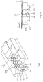
- the suction device 5 there are support strips 55 rigidly arranged on the support frame 52, to which the non-adjustable support elements 53 are fastened, and their distance from the top of the support frame 52 is adjustable Support strips 56 to which the adjustable support elements 54 are attached. Furthermore, the inner edges 52b of the supports 52a are provided transversely to the direction of movement A of the sieve belt 1 with sections running at an acute angle, in particular being designed in a wavy line.
- the support frame 52 is formed on its sides assigned to the regions of the edges of the sieve belt 1 with parts 57 which can be adjusted transversely thereto, by means of which the size of the suction opening can be adjusted.
- These parts 57 are also provided with highly wear-resistant pads 57a.
- the front edge of the support 52a in the direction of movement A of the sieve belt 1 is formed with a wedge-shaped extension 52b, by means of which the stripping effect of the device 5 is improved.
- the sieve belt 1 Due to the different heights of the support elements 53 and 54 the sieve belt 1 is wavy as it moves over the support elements 53 and 54 moves, subjecting it to tensile loads. Through the the sieve belt 1 is also at wavy edges 52b its movement across the support frame 52 with in its plane transverse to Direction of movement A subjected to tensile loads. Through both this tensile loads causes the contaminants located in the filter belt 1 and liquids are more easily removed therefrom, so that the drainage of liquid from the paper pulp is facilitated. hereby also the effect of the suction forces exerted on the sieve belt 1 significantly improved. In addition, these tensile loads in the paper tape Turbulence created by which the quality of the paper tape being affected.
- the supporting frame 42 of the device 4 according to FIG. 2 has the same structure on, although no vacuum source connected to this device is.
- the ones assigned to the felt band 2 Suction devices 6 have a similar structure. Also there are within the support frame 62 fixed support bars 65 with support elements 63 and 2 adjustable support strips 66 with respect to the felt band adjustable support elements 64 and are the borders 62b of the supports 62a transverse to the direction of movement B of the felt belts 2 in a wavy line educated. Due to the tensile loads exerted on the felt belts 2 as they move over the suction devices 6 stretched in several directions, causing impurities contained in them and liquids are removed more easily and the effect of suction force exerted on the felt belts 2 is increased.
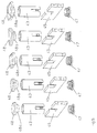
- the support elements 43 can be designed as tubular pieces which are placed on the support strips 45 by means of slots which are assigned to one another, their attachment to the support strips 45 being carried out by means of a screw element 47.
- a cap 48 is inserted into the end of the pipe sections facing the sieve belt 1 or the felt belt 2.
- the caps 48 are formed with cylindrical extensions, by means of which they are inserted into the pipe sections.
- the caps 48 are made of a highly wear-resistant material, in particular a ceramic material.
- the caps 48 can have different spatial configurations. In particular, they can be chamfered, in particular bevelled, or rounded. In addition, these caps 48 can be curved in relation to the sieve belt 1.
- the movable support elements 44 and the support elements 53 and 54 as well as the support elements 63 and 64 can be designed in the same way and fastened on fixed or adjustable support strips.
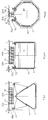
- the housing 41 of the device 4 can be pushed back and forth in the direction of the double arrow C, wherein an actuator 72 is assigned to it, by means of which it is via an eccentric shaft 73 and a push rod 74 with oscillating movements is.
- the support frame 42 is on Housing 41 mounted in the direction of the double arrow C back and forth and are driven by the drive motor 72 via the eccentric shaft 73 and the push rod 74 transverse to the directions of movement A of the sieve belt 1 oscillating movements C.
- the Support frame 52 and 62 transverse to the directions of movement A and B of the Sieve belt 1 or the felt belts 2 can be slidably mounted.
- the sieve belt 1 or the felt belts 2 are reinforced by in tensile loads acting in several directions, thereby their Effects, especially their suction effects, are further increased.
Landscapes
- Paper (AREA)
- Treatment Of Fiber Materials (AREA)
- Preliminary Treatment Of Fibers (AREA)
Abstract
Description
- Fig.1
- eine Anlage zur Papiererzeugung, welche mit erfindungsgemäßen Vorrichtungen versehen ist, in schematischer Darstellung;
- Fig.2, Fig.2a, Fig.2b
- drei unterschiedliche Ausführungsformen von erfindungsgemäßen Vorrichtungen, in Seitenansicht bzw. im Schnitt:
- Fig.3, Fig.3a
- eine vierte Ausführungsform einer erfindungsgemäßen Vorrichtung, in axonometrischer Darstellung und in Seitenansicht;
- Fig.4, Fig.4a
- eine fünfte Ausführungsform einer erfindungsgemäßen Vorrichtung, in axonometrischer Darstellung und in Seitenansicht;
- Fig.5
- fünf unterschiedlich ausgebildete Stützelemente, jeweils in axonometrischer Darstellung, und
- Fig.6, Fig.6a
- erfindungsgemäße Vorrichtungen, welche quer zur Bewegungsrichtung des Siebbandes bzw. des Filzbandes oszillierende Bewegungen ausführen können.
Wie dies aus Fig.3a gleichfalls ersichtlich ist, ist weiters die in Bewegungsrichtung A des Siebbandes 1 vordere Kante der Auflage 52a mit einem keilförmigen Fortsatz 52b ausgebildet, durch welchen die Abstreifwirkung der Vorrichtung 5 verbessert wird.
Die beweglichen Stützelemente 44 sowie die Stützelemente 53 und 54 ebenso wie die Stützelemente 63 und 64 können in der gleichen Weise ausgebildet und auf festen bzw. verstellbaren Tragleisten befestigt sein.
Claims (13)
- Vorrichtung zur Behandlung, insbesondere zur Unterdruck-Beaufschlagung, des in einer Anlage zur Papiererzeugung vorgesehenen, im Umlauf bewegten mindestens einen Siebbandes (1) bzw. mindestens einen Filzbandes (2), an welche Vorrichtung gegebenenfalls eine Unterdruckquelle angeschlossen ist, gekennzeichnet durch eine dem Siebband (1) bzw. dem Filzband (2) zugeordnete Trageinrichtung (42, 52, 62) mit einer Vielzahl von im Abstand voneinander angeordneten Stützelementen (43, 44, 53, 54, 63, 64).
- Vorrichtung nach Patentanspruch 1, dadurch gekennzeichnet, daß die Stützelemente (43, 44, 53, 54, 63, 64) an ihrem dem Siebband (1) bzw. dem Filzband (2) zugewandten Seite mit gegenüber der Bewegung des Siebbandes (1) bzw. des Filzbandes (2) verschleißfesten Auflagen (43a, 44a, 53a, 54a, 63a, 64a) ausgebildet sind.
- Vorrichtung nach einem der Patentansprüche 1 und 2, dadurch gekennzeichnet, daß Stützelemente (44,54,64) gegenüber der Trageinrichtung (42,52,62) in Bezug auf ihren Abstand gegenüber dem Siebband (1) bzw. dem Filzband (2) verstellbar sind.
- Vorrichtung nach Patentanspruch 3, dadurch gekennzeichnet, daß Stützelemente (44,54,64) auf gegenüber dem Siebband (1) bzw. dem Filzband (2) verstellbaren Tragleisten (56,66) angeordnet sind.
- Vorrichtung nach einem der Patentansprüche 3 und 4, dadurch gekennzeichnet, daß ein Teil der Stützelemente (43,53,63) an der Trageinrichtung (42,52,62) starr befestigt ist und daß ein Teil derselben gegenüber der Trageinrichtung (42,52,62) verstellbar ist.
- Vorrichtung nach einem der Patentansprüche 3 bis 5, dadurch gekennzeichnet, daß die Stützelemente (43, 44, 53, 54, 63, 64) nebeneinander auf zur Bewegungsrichtung (A, B) des Siebbandes (1) bzw. des Filzbandes (2) quer ausgerichteten Tragleisten (55, 56, 65, 66) angeordnet sind, wobei vorzugsweise zumindest ein Teil der Tragleisten (56, 66) gegenüber den Trageinrichtungen (42, 52, 62) verstellbar ist.
- Vorrichtung nach einem der Patentansprüche 1 bis 6, dadurch gekennzeichnet, daß die dem Siebband (1) bzw. dem Filzband (2) zugewandte Seite der Trageinrichtung (42, 52, 62) mit einer aus gegenüber der Bewegung des Siebbandes (1) bzw. des Filzbandes (2) verschleißfesten Auflage (52a, 62a) versehen ist, wobei die den quer zur Bewegungsrichtung (A,B) des Siebbandes (1) bzw. des Filzbandes (2) den Stützelementen (53, 54, 63, 64) zugewandten Berandungen (52b, 62b) der Auflage (52a, 62a) mit zur Bewegungsrichtung des Siebbandes (1) bzw. des Filzbandes (2) im spitzen Winkel verlaufenden Abschnitten ausgebildet sind.
- Vorrichtung nach Patentanspruch 7, dadurch gekennzeichnet, daß die quer zur Bewegungsrichtung (A, B) des Siebbandes (1) bzw. des Filzbandes (2) verlaufenden Berandungen (52b, 62b) der Auflage (52a, 62a) wellenförmig ausgebildet sind.
- Vorrichtung nach einem der Patentansprüche 1 bis 8, dadurch gekennzeichnet, daß die Trageinrichtung (52, 62) quer zur Bewegungsrichtung (A, B) des Siebbandes (1) bzw. des Filzbandes (2) verstellbar angeordnet ist, wobei ihr eine Antriebseinrichtung (72) zugeordnet ist, mittels welcher sie quer zur Bewegungsrichtung (A, B) des Siebbandes (1) bzw. des Filzbandes (2) oszillierbar ist.
- Vorrichtung nach einem der Patentansprüche 1 bis 9, dadurch gekennzeichnet, daß die Trageinrichtung (52, 62) einen Teil eines Saugkastens bildet, wobei vorzugsweise der Saugkasten mittels der Antriebseinrichtung (72) quer zur Bewegungsrichtung (A, B) des Siebbandes (1) bzw. des Filzbandes (2) oszillierbar ausgebildet ist.
- Vorrichtung nach einem der Patentansprüche 1 bis 10, dadurch gekennzeichnet, daß die Stützelemente (43) als Rohrstücke ausgebildet sind, in welche an deren dem Siebband (1) bzw. dem Filzband (2) zugewandten Ende Elemente (48) aus einem gegenüber der Bewegung des Siebbandes (1) bzw. des Filzbandes (2) verschleißfesten Material eingesetzt sind.
- Vorrichtung nach Patentanspruch 11, dadurch gekennzeichnet, daß die Kanten der dem Siebband (1) bzw. dem Filzband (2) zugewandten Oberseiten der Elemente (48) abgefast, insbesondere abgeschrägt, oder abgerundet ausgebildet sind und daß diese Elemente (48) an den gegenüberliegenden Seiten mit Fortsätzen (48a) ausgebildet sind, mittels welcher sie in die Rohrstücke einsetzbar sind.
- Vorrichtung nach einem der Patentansprüche 11 und 12, dadurch gekennzeichnet, daß die Elemente (48) mit einer gegenüber dem Siebband (1) bzw. dem Filzband (2) ausgewölbten Oberfläche ausgebildet sind.
Priority Applications (1)
| Application Number | Priority Date | Filing Date | Title |
|---|---|---|---|
| EP10450007A EP2210977B1 (de) | 2003-02-20 | 2003-09-11 | Vorrichtung zur Behandlung, insbesondere zur Unterdruck-Beaufschlagung, des in einer Anlage zur Papiererzeugung vorgesehenen, im Umlauf bewegten mindestens einen Siebbandes bzw. Filzbandes |
Applications Claiming Priority (2)
| Application Number | Priority Date | Filing Date | Title |
|---|---|---|---|
| AT2572003 | 2003-02-20 | ||
| AT0025703A AT500751B8 (de) | 2003-02-20 | 2003-02-20 | Vorrichtung zur behandlung, insbesondere zur unterdruck-beaufschlagung, des in einer anlage zur papiererzeugung vorgesehenen, im umlauf bewegten mindestens einen siebbandes bzw. filzbandes |
Publications (2)
| Publication Number | Publication Date |
|---|---|
| EP1449958A1 true EP1449958A1 (de) | 2004-08-25 |
| EP1449958B1 EP1449958B1 (de) | 2010-03-17 |
Family
ID=32719879
Family Applications (2)
| Application Number | Title | Priority Date | Filing Date |
|---|---|---|---|
| EP03450202A Expired - Lifetime EP1449958B1 (de) | 2003-02-20 | 2003-09-11 | Vorrichtung zur Behandlung insbesondere zur Unterdruck-Beaufschlagung, des in einer Anlage zur Papiererzeugung vorgesehenen im Umlauf bewgten mindestens einen Siebbandes bzw. Filzbandes |
| EP10450007A Expired - Lifetime EP2210977B1 (de) | 2003-02-20 | 2003-09-11 | Vorrichtung zur Behandlung, insbesondere zur Unterdruck-Beaufschlagung, des in einer Anlage zur Papiererzeugung vorgesehenen, im Umlauf bewegten mindestens einen Siebbandes bzw. Filzbandes |
Family Applications After (1)
| Application Number | Title | Priority Date | Filing Date |
|---|---|---|---|
| EP10450007A Expired - Lifetime EP2210977B1 (de) | 2003-02-20 | 2003-09-11 | Vorrichtung zur Behandlung, insbesondere zur Unterdruck-Beaufschlagung, des in einer Anlage zur Papiererzeugung vorgesehenen, im Umlauf bewegten mindestens einen Siebbandes bzw. Filzbandes |
Country Status (8)
| Country | Link |
|---|---|
| US (1) | US7175744B2 (de) |
| EP (2) | EP1449958B1 (de) |
| JP (1) | JP4109179B2 (de) |
| CN (1) | CN1327080C (de) |
| AT (3) | AT500751B8 (de) |
| CA (1) | CA2444684C (de) |
| DE (1) | DE50312520D1 (de) |
| ES (2) | ES2362857T3 (de) |
Cited By (1)
| Publication number | Priority date | Publication date | Assignee | Title |
|---|---|---|---|---|
| WO2011151239A3 (de) * | 2010-06-01 | 2012-01-26 | Voith Patent Gmbh | Maschine zur herstellung einer papierbahn insbesondere sackpapierbahn |
Families Citing this family (5)
| Publication number | Priority date | Publication date | Assignee | Title |
|---|---|---|---|---|
| JP5716378B2 (ja) * | 2010-12-17 | 2015-05-13 | 王子ホールディングス株式会社 | 繊維シートの製造装置 |
| AT518060B1 (de) | 2016-07-07 | 2017-07-15 | Klaus Ing Bartelmuss | Vorrichtung zur Reinigung eines Filzbandes in einer Anlage zur Herstellung eines Papierbandes |
| DE102018119686A1 (de) * | 2018-08-14 | 2020-02-20 | Voith Patent Gmbh | Papiermaschine |
| US12146265B2 (en) * | 2020-06-02 | 2024-11-19 | First Quality Tissue, Llc | Dewatering box cover |
| DE102025000203A1 (de) * | 2025-01-20 | 2025-12-31 | Voith Patent Gmbh | Verfahren zum Betrieb einer Presseinheit in einer Maschine zur Herstellung einer Faserstoffbahn |
Citations (8)
| Publication number | Priority date | Publication date | Assignee | Title |
|---|---|---|---|---|
| DE690425C (de) * | 1937-02-19 | 1940-04-25 | Rohrbacher Lederfabrik Jos Poe | Saugkasten, insbesondere fuer Papiermaschinen |
| DE1761174A1 (de) | 1967-04-17 | 1971-06-16 | Leder & Riemen Patent | Bauteil fuer Papiermaschinen oder Zellstoffentwaesserungsmaschinen |
| DE2126591A1 (en) * | 1971-05-28 | 1972-12-07 | Feldmühle Anlagen- und Produktionsgesellschaft mbH, 4000 Düsseldorf | Paper making machine - has scraper blades mounted beneath the paper in the liquid extractor |
| US3778342A (en) * | 1971-04-12 | 1973-12-11 | Jwi Ltd | Wear resistant outsert for a paper machine foil |
| DE3933506A1 (de) * | 1988-10-06 | 1990-04-12 | Bartelmuss Heinrich Ing | Belag |
| EP0454973A1 (de) * | 1990-05-04 | 1991-11-06 | Wilbanks International | Saugkastenvorrichtung mit Verbunddeckelelementen eingesetzt in Schlitze auf Querträgern |
| US5262010A (en) * | 1991-03-09 | 1993-11-16 | Sulzer Escher Wyss Gmbh | Dewatering device with adjustable force elements for the web-forming section of a papermaking machine |
| DE10109413A1 (de) * | 2001-02-27 | 2002-09-05 | Voith Paper Patent Gmbh | Verfahren und Vorrichtung zur Verbesserung der Eigenschaften einer in einer Blattbildungseinrichtung hergestellten Faserstoffbahn |
Family Cites Families (14)
| Publication number | Priority date | Publication date | Assignee | Title |
|---|---|---|---|---|
| US1917098A (en) * | 1932-02-02 | 1933-07-04 | Austin E Cofrin | Apparatus and process for making paper |
| US2124028A (en) * | 1934-12-17 | 1938-07-19 | Int Paper Co | Process and apparatus for the manufacture of paper |
| US3357881A (en) * | 1964-10-15 | 1967-12-12 | Fitchburg Paper | Wire support for papermaking machines |
| US3585105A (en) * | 1967-05-26 | 1971-06-15 | Beloit Corp | Anti-deflection drain board method and apparatus |
| DE2029617C3 (de) * | 1970-06-16 | 1975-12-18 | Feldmuehle Anlagen- Und Produktionsgesellschaft Mbh, 4000 Duesseldorf | Entwässerungseinrichtung für die Siebpartie von Langsiebpapiermaschinen |
| AT313697B (de) * | 1970-06-16 | 1974-02-25 | Feldmuehle Anlagen Prod | Entwässerungselement für die Naßpartie einer Papiermaschine |
| US3922190A (en) * | 1972-05-01 | 1975-11-25 | Inotech Process Ltd | Vacuum drainage device having a plurality of stepped blades |
| US3821077A (en) * | 1972-06-19 | 1974-06-28 | Scott Paper Co | Support structure for supporting a moving web-forming wire in a forming zone |
| CA1021974A (en) | 1974-08-06 | 1977-12-06 | Jwi Ltd. | Paper machine shake |
| US4191612A (en) * | 1978-07-05 | 1980-03-04 | Ikuo Araoka | Dewatering suction apparatus for paper making machine |
| AT389534B (de) * | 1987-06-04 | 1989-12-27 | Albert Hans | Vorrichtung zur entwaesserung einer auf einem sieb transportierten stoffbahn |
| US5076894A (en) * | 1990-05-04 | 1991-12-31 | Simmons Holt W | Suction box apparatus with composite cover elements mounted in slots on cross braces |
| KR100528374B1 (ko) * | 2000-10-16 | 2005-11-15 | 아스텐존슨 인코포레이티드 | 제지기에서의 시트 특성 개선 방법 및 장치 |
| AT412657B (de) * | 2002-10-17 | 2005-05-25 | Bartelmuss Klaus Ing | Vorrichtung für eine mindestens ein siebband aufweisende anlage zur papiererzeugung |
-
2003
- 2003-02-20 AT AT0025703A patent/AT500751B8/de not_active IP Right Cessation
- 2003-09-11 EP EP03450202A patent/EP1449958B1/de not_active Expired - Lifetime
- 2003-09-11 DE DE50312520T patent/DE50312520D1/de not_active Expired - Lifetime
- 2003-09-11 ES ES10450007T patent/ES2362857T3/es not_active Expired - Lifetime
- 2003-09-11 AT AT03450202T patent/ATE461317T1/de active
- 2003-09-11 ES ES03450202T patent/ES2339233T3/es not_active Expired - Lifetime
- 2003-09-11 EP EP10450007A patent/EP2210977B1/de not_active Expired - Lifetime
- 2003-09-11 AT AT10450007T patent/ATE511572T1/de active
- 2003-10-09 US US10/682,639 patent/US7175744B2/en not_active Expired - Fee Related
- 2003-10-15 CA CA002444684A patent/CA2444684C/en not_active Expired - Fee Related
- 2003-10-21 JP JP2003360676A patent/JP4109179B2/ja not_active Expired - Fee Related
-
2004
- 2004-02-18 CN CNB2004100054173A patent/CN1327080C/zh not_active Expired - Fee Related
Patent Citations (8)
| Publication number | Priority date | Publication date | Assignee | Title |
|---|---|---|---|---|
| DE690425C (de) * | 1937-02-19 | 1940-04-25 | Rohrbacher Lederfabrik Jos Poe | Saugkasten, insbesondere fuer Papiermaschinen |
| DE1761174A1 (de) | 1967-04-17 | 1971-06-16 | Leder & Riemen Patent | Bauteil fuer Papiermaschinen oder Zellstoffentwaesserungsmaschinen |
| US3778342A (en) * | 1971-04-12 | 1973-12-11 | Jwi Ltd | Wear resistant outsert for a paper machine foil |
| DE2126591A1 (en) * | 1971-05-28 | 1972-12-07 | Feldmühle Anlagen- und Produktionsgesellschaft mbH, 4000 Düsseldorf | Paper making machine - has scraper blades mounted beneath the paper in the liquid extractor |
| DE3933506A1 (de) * | 1988-10-06 | 1990-04-12 | Bartelmuss Heinrich Ing | Belag |
| EP0454973A1 (de) * | 1990-05-04 | 1991-11-06 | Wilbanks International | Saugkastenvorrichtung mit Verbunddeckelelementen eingesetzt in Schlitze auf Querträgern |
| US5262010A (en) * | 1991-03-09 | 1993-11-16 | Sulzer Escher Wyss Gmbh | Dewatering device with adjustable force elements for the web-forming section of a papermaking machine |
| DE10109413A1 (de) * | 2001-02-27 | 2002-09-05 | Voith Paper Patent Gmbh | Verfahren und Vorrichtung zur Verbesserung der Eigenschaften einer in einer Blattbildungseinrichtung hergestellten Faserstoffbahn |
Cited By (1)
| Publication number | Priority date | Publication date | Assignee | Title |
|---|---|---|---|---|
| WO2011151239A3 (de) * | 2010-06-01 | 2012-01-26 | Voith Patent Gmbh | Maschine zur herstellung einer papierbahn insbesondere sackpapierbahn |
Also Published As
| Publication number | Publication date |
|---|---|
| ES2339233T3 (es) | 2010-05-18 |
| ES2362857T3 (es) | 2011-07-14 |
| US7175744B2 (en) | 2007-02-13 |
| JP4109179B2 (ja) | 2008-07-02 |
| CA2444684A1 (en) | 2004-08-20 |
| AT500751B1 (de) | 2006-08-15 |
| JP2004250854A (ja) | 2004-09-09 |
| AT500751A1 (de) | 2006-03-15 |
| EP2210977B1 (de) | 2011-06-01 |
| CN1523163A (zh) | 2004-08-25 |
| ATE511572T1 (de) | 2011-06-15 |
| EP1449958B1 (de) | 2010-03-17 |
| DE50312520D1 (de) | 2010-04-29 |
| CA2444684C (en) | 2007-09-18 |
| EP2210977A1 (de) | 2010-07-28 |
| CN1327080C (zh) | 2007-07-18 |
| ATE461317T1 (de) | 2010-04-15 |
| AT500751B8 (de) | 2007-02-15 |
| US20040163787A1 (en) | 2004-08-26 |
Similar Documents
| Publication | Publication Date | Title |
|---|---|---|
| DE2509349C2 (de) | Vorrichtung zum Verdichten und Waschen oder dgl. einer Faserbreisuspension | |
| EP0818568A2 (de) | Verfahren und Vorrichtung zum hydrodynamischen Verschlingen der Fasern einer Faserbahn | |
| DE7717998U1 (de) | Vorrichtung zum entwaessern von rueckstaenden, wie schlaemmen o.dgl. | |
| DE3329833C2 (de) | Vorrichtung zur Entwässerung einer Papierbahn oder dergleichen | |
| DE102004044399A1 (de) | Schmiermittelsäuberungsvorrichtung fürs Trockendrahtziehen | |
| DE2944889A1 (de) | Vorrichtung zum absaugen von faserfoermigem material | |
| DE3877883T2 (de) | Filterpresse mit endlosen filterbaendern. | |
| DE2505989C3 (de) | Kontinuierlich arbeitende Presse | |
| EP1449958B1 (de) | Vorrichtung zur Behandlung insbesondere zur Unterdruck-Beaufschlagung, des in einer Anlage zur Papiererzeugung vorgesehenen im Umlauf bewgten mindestens einen Siebbandes bzw. Filzbandes | |
| DE1760381B2 (de) | Vorrichtung zum kontinuierlichen Entwässern von Leder oder lederartigem Material | |
| EP2885454A1 (de) | Dichteinrichtung und walze mit dichteinrichtung | |
| AT401185B (de) | Vorrichtung zur entwässerung und bzw. oder wäsche von suspensionen, insbesondere faserstoffsuspensionen | |
| EP0816560A2 (de) | Pressvorrichtung | |
| DE2850771A1 (de) | Verfahren und vorrichtung zum entwaessern von schlamm | |
| DE3003827C2 (de) | Einrichtung zur mechanischen Reinigung von Wässern | |
| DE4302922C1 (de) | Verfahren und Vorrichtung zum Behandeln von Schlämmen | |
| EP3030712B1 (de) | Anordnung zum spannen eines formiersiebes einer papiermaschine | |
| EP0101428A2 (de) | Vorrichtung zum Entwässern von wasserhaltigen Stoffen | |
| WO1999040994A1 (de) | Eindicker | |
| AT93532B (de) | Walzenpresse zum Auspressen von Flüssigkeit aus Faserstoffen. | |
| DE9105797U1 (de) | Doppelsiebpartie einer Papier- oder Kartonmaschine | |
| EP1411166A2 (de) | Vorrichtung für eine mindestens ein Siebband aufweisende Anlage zur Papiererzeugung | |
| DE2526697C2 (de) | Vorrichtung zur Herstellung eines Faservliesbandes | |
| DE3102022A1 (de) | Vorrichtung zur kontinuierlichen absaugentwaesserung von textilen warenbahnen | |
| DE10144257B4 (de) | Vorrichtung zur Herstellung von Granulat |
Legal Events
| Date | Code | Title | Description |
|---|---|---|---|
| PUAI | Public reference made under article 153(3) epc to a published international application that has entered the european phase |
Free format text: ORIGINAL CODE: 0009012 |
|
| AK | Designated contracting states |
Kind code of ref document: A1 Designated state(s): AT BE BG CH CY CZ DE DK EE ES FI FR GB GR HU IE IT LI LU MC NL PT RO SE SI SK TR |
|
| AX | Request for extension of the european patent |
Extension state: AL LT LV MK |
|
| 17P | Request for examination filed |
Effective date: 20040826 |
|
| 17Q | First examination report despatched |
Effective date: 20050308 |
|
| AKX | Designation fees paid |
Designated state(s): AT BE BG CH CY CZ DE DK EE ES FI FR GB GR HU IE IT LI LU MC NL PT RO SE SI SK TR |
|
| GRAP | Despatch of communication of intention to grant a patent |
Free format text: ORIGINAL CODE: EPIDOSNIGR1 |
|
| GRAS | Grant fee paid |
Free format text: ORIGINAL CODE: EPIDOSNIGR3 |
|
| GRAA | (expected) grant |
Free format text: ORIGINAL CODE: 0009210 |
|
| AK | Designated contracting states |
Kind code of ref document: B1 Designated state(s): AT BE BG CH CY CZ DE DK EE ES FI FR GB GR HU IE IT LI LU MC NL PT RO SE SI SK TR |
|
| REG | Reference to a national code |
Ref country code: GB Ref legal event code: FG4D Free format text: NOT ENGLISH |
|
| REG | Reference to a national code |
Ref country code: CH Ref legal event code: EP |
|
| REG | Reference to a national code |
Ref country code: IE Ref legal event code: FG4D |
|
| REF | Corresponds to: |
Ref document number: 50312520 Country of ref document: DE Date of ref document: 20100429 Kind code of ref document: P |
|
| REG | Reference to a national code |
Ref country code: SE Ref legal event code: TRGR |
|
| REG | Reference to a national code |
Ref country code: CH Ref legal event code: NV Representative=s name: LUCHS & PARTNER PATENTANWAELTE |
|
| REG | Reference to a national code |
Ref country code: ES Ref legal event code: FG2A Ref document number: 2339233 Country of ref document: ES Kind code of ref document: T3 |
|
| REG | Reference to a national code |
Ref country code: NL Ref legal event code: VDEP Effective date: 20100317 |
|
| PG25 | Lapsed in a contracting state [announced via postgrant information from national office to epo] |
Ref country code: SI Free format text: LAPSE BECAUSE OF FAILURE TO SUBMIT A TRANSLATION OF THE DESCRIPTION OR TO PAY THE FEE WITHIN THE PRESCRIBED TIME-LIMIT Effective date: 20100317 |
|
| REG | Reference to a national code |
Ref country code: IE Ref legal event code: FD4D |
|
| PG25 | Lapsed in a contracting state [announced via postgrant information from national office to epo] |
Ref country code: NL Free format text: LAPSE BECAUSE OF FAILURE TO SUBMIT A TRANSLATION OF THE DESCRIPTION OR TO PAY THE FEE WITHIN THE PRESCRIBED TIME-LIMIT Effective date: 20100317 Ref country code: GR Free format text: LAPSE BECAUSE OF FAILURE TO SUBMIT A TRANSLATION OF THE DESCRIPTION OR TO PAY THE FEE WITHIN THE PRESCRIBED TIME-LIMIT Effective date: 20100618 Ref country code: EE Free format text: LAPSE BECAUSE OF FAILURE TO SUBMIT A TRANSLATION OF THE DESCRIPTION OR TO PAY THE FEE WITHIN THE PRESCRIBED TIME-LIMIT Effective date: 20100317 Ref country code: CY Free format text: LAPSE BECAUSE OF FAILURE TO SUBMIT A TRANSLATION OF THE DESCRIPTION OR TO PAY THE FEE WITHIN THE PRESCRIBED TIME-LIMIT Effective date: 20100317 Ref country code: RO Free format text: LAPSE BECAUSE OF FAILURE TO SUBMIT A TRANSLATION OF THE DESCRIPTION OR TO PAY THE FEE WITHIN THE PRESCRIBED TIME-LIMIT Effective date: 20100317 |
|
| PG25 | Lapsed in a contracting state [announced via postgrant information from national office to epo] |
Ref country code: BG Free format text: LAPSE BECAUSE OF FAILURE TO SUBMIT A TRANSLATION OF THE DESCRIPTION OR TO PAY THE FEE WITHIN THE PRESCRIBED TIME-LIMIT Effective date: 20100617 Ref country code: SK Free format text: LAPSE BECAUSE OF FAILURE TO SUBMIT A TRANSLATION OF THE DESCRIPTION OR TO PAY THE FEE WITHIN THE PRESCRIBED TIME-LIMIT Effective date: 20100317 Ref country code: CZ Free format text: LAPSE BECAUSE OF FAILURE TO SUBMIT A TRANSLATION OF THE DESCRIPTION OR TO PAY THE FEE WITHIN THE PRESCRIBED TIME-LIMIT Effective date: 20100317 |
|
| PLBE | No opposition filed within time limit |
Free format text: ORIGINAL CODE: 0009261 |
|
| STAA | Information on the status of an ep patent application or granted ep patent |
Free format text: STATUS: NO OPPOSITION FILED WITHIN TIME LIMIT |
|
| PG25 | Lapsed in a contracting state [announced via postgrant information from national office to epo] |
Ref country code: DK Free format text: LAPSE BECAUSE OF FAILURE TO SUBMIT A TRANSLATION OF THE DESCRIPTION OR TO PAY THE FEE WITHIN THE PRESCRIBED TIME-LIMIT Effective date: 20100317 Ref country code: PT Free format text: LAPSE BECAUSE OF FAILURE TO SUBMIT A TRANSLATION OF THE DESCRIPTION OR TO PAY THE FEE WITHIN THE PRESCRIBED TIME-LIMIT Effective date: 20100719 Ref country code: IE Free format text: LAPSE BECAUSE OF FAILURE TO SUBMIT A TRANSLATION OF THE DESCRIPTION OR TO PAY THE FEE WITHIN THE PRESCRIBED TIME-LIMIT Effective date: 20100317 |
|
| 26N | No opposition filed |
Effective date: 20101220 |
|
| BERE | Be: lapsed |
Owner name: BARTELMUSS, HEINZ Effective date: 20100930 Owner name: BARTELMUSS, KLAUS Effective date: 20100930 |
|
| PG25 | Lapsed in a contracting state [announced via postgrant information from national office to epo] |
Ref country code: MC Free format text: LAPSE BECAUSE OF NON-PAYMENT OF DUE FEES Effective date: 20100930 |
|
| PG25 | Lapsed in a contracting state [announced via postgrant information from national office to epo] |
Ref country code: BE Free format text: LAPSE BECAUSE OF NON-PAYMENT OF DUE FEES Effective date: 20100930 |
|
| PG25 | Lapsed in a contracting state [announced via postgrant information from national office to epo] |
Ref country code: HU Free format text: LAPSE BECAUSE OF FAILURE TO SUBMIT A TRANSLATION OF THE DESCRIPTION OR TO PAY THE FEE WITHIN THE PRESCRIBED TIME-LIMIT Effective date: 20100918 Ref country code: LU Free format text: LAPSE BECAUSE OF NON-PAYMENT OF DUE FEES Effective date: 20100911 |
|
| PG25 | Lapsed in a contracting state [announced via postgrant information from national office to epo] |
Ref country code: TR Free format text: LAPSE BECAUSE OF FAILURE TO SUBMIT A TRANSLATION OF THE DESCRIPTION OR TO PAY THE FEE WITHIN THE PRESCRIBED TIME-LIMIT Effective date: 20100317 |
|
| REG | Reference to a national code |
Ref country code: FR Ref legal event code: PLFP Year of fee payment: 14 |
|
| PGFP | Annual fee paid to national office [announced via postgrant information from national office to epo] |
Ref country code: CH Payment date: 20160920 Year of fee payment: 14 Ref country code: DE Payment date: 20160921 Year of fee payment: 14 Ref country code: GB Payment date: 20160920 Year of fee payment: 14 Ref country code: FI Payment date: 20160913 Year of fee payment: 14 |
|
| PGFP | Annual fee paid to national office [announced via postgrant information from national office to epo] |
Ref country code: AT Payment date: 20160927 Year of fee payment: 14 Ref country code: FR Payment date: 20160921 Year of fee payment: 14 Ref country code: SE Payment date: 20160920 Year of fee payment: 14 |
|
| PGFP | Annual fee paid to national office [announced via postgrant information from national office to epo] |
Ref country code: ES Payment date: 20160916 Year of fee payment: 14 |
|
| PGFP | Annual fee paid to national office [announced via postgrant information from national office to epo] |
Ref country code: IT Payment date: 20160922 Year of fee payment: 14 |
|
| REG | Reference to a national code |
Ref country code: DE Ref legal event code: R119 Ref document number: 50312520 Country of ref document: DE |
|
| PG25 | Lapsed in a contracting state [announced via postgrant information from national office to epo] |
Ref country code: FI Free format text: LAPSE BECAUSE OF NON-PAYMENT OF DUE FEES Effective date: 20170911 |
|
| REG | Reference to a national code |
Ref country code: CH Ref legal event code: PL |
|
| REG | Reference to a national code |
Ref country code: SE Ref legal event code: EUG |
|
| REG | Reference to a national code |
Ref country code: AT Ref legal event code: MM01 Ref document number: 461317 Country of ref document: AT Kind code of ref document: T Effective date: 20170911 |
|
| GBPC | Gb: european patent ceased through non-payment of renewal fee |
Effective date: 20170911 |
|
| REG | Reference to a national code |
Ref country code: FR Ref legal event code: ST Effective date: 20180531 |
|
| PG25 | Lapsed in a contracting state [announced via postgrant information from national office to epo] |
Ref country code: LI Free format text: LAPSE BECAUSE OF NON-PAYMENT OF DUE FEES Effective date: 20170930 Ref country code: CH Free format text: LAPSE BECAUSE OF NON-PAYMENT OF DUE FEES Effective date: 20170930 Ref country code: GB Free format text: LAPSE BECAUSE OF NON-PAYMENT OF DUE FEES Effective date: 20170911 Ref country code: DE Free format text: LAPSE BECAUSE OF NON-PAYMENT OF DUE FEES Effective date: 20180404 |
|
| PG25 | Lapsed in a contracting state [announced via postgrant information from national office to epo] |
Ref country code: IT Free format text: LAPSE BECAUSE OF NON-PAYMENT OF DUE FEES Effective date: 20170911 Ref country code: AT Free format text: LAPSE BECAUSE OF NON-PAYMENT OF DUE FEES Effective date: 20170911 Ref country code: FR Free format text: LAPSE BECAUSE OF NON-PAYMENT OF DUE FEES Effective date: 20171002 |
|
| REG | Reference to a national code |
Ref country code: ES Ref legal event code: FD2A Effective date: 20181019 |
|
| PG25 | Lapsed in a contracting state [announced via postgrant information from national office to epo] |
Ref country code: ES Free format text: LAPSE BECAUSE OF NON-PAYMENT OF DUE FEES Effective date: 20170912 |
|
| PG25 | Lapsed in a contracting state [announced via postgrant information from national office to epo] |
Ref country code: SE Free format text: LAPSE BECAUSE OF NON-PAYMENT OF DUE FEES Effective date: 20170912 |