EP1449691B1 - Procédé d'admission d'air pour système de conditionnement d'air de véhicule avec un détecteur de la qualité de l'air - Google Patents
Procédé d'admission d'air pour système de conditionnement d'air de véhicule avec un détecteur de la qualité de l'air Download PDFInfo
- Publication number
- EP1449691B1 EP1449691B1 EP04075352A EP04075352A EP1449691B1 EP 1449691 B1 EP1449691 B1 EP 1449691B1 EP 04075352 A EP04075352 A EP 04075352A EP 04075352 A EP04075352 A EP 04075352A EP 1449691 B1 EP1449691 B1 EP 1449691B1
- Authority
- EP
- European Patent Office
- Prior art keywords
- air
- inlet
- valve
- mode
- outside
- Prior art date
- Legal status (The legal status is an assumption and is not a legal conclusion. Google has not performed a legal analysis and makes no representation as to the accuracy of the status listed.)
- Expired - Lifetime
Links
- 238000000034 method Methods 0.000 title claims description 21
- 230000007704 transition Effects 0.000 claims description 7
- 238000003915 air pollution Methods 0.000 description 7
- 239000003507 refrigerant Substances 0.000 description 6
- 238000010586 diagram Methods 0.000 description 4
- 238000001816 cooling Methods 0.000 description 3
- 238000001914 filtration Methods 0.000 description 3
- 238000004378 air conditioning Methods 0.000 description 2
- 239000007788 liquid Substances 0.000 description 2
- 238000012986 modification Methods 0.000 description 2
- 230000004048 modification Effects 0.000 description 2
- 235000019645 odor Nutrition 0.000 description 2
- 238000011144 upstream manufacturing Methods 0.000 description 2
- 239000002826 coolant Substances 0.000 description 1
- 230000001351 cycling effect Effects 0.000 description 1
- 230000000694 effects Effects 0.000 description 1
- 239000003344 environmental pollutant Substances 0.000 description 1
- 238000010438 heat treatment Methods 0.000 description 1
- 231100000719 pollutant Toxicity 0.000 description 1
- 238000010926 purge Methods 0.000 description 1
- 239000000779 smoke Substances 0.000 description 1
- 230000000153 supplemental effect Effects 0.000 description 1
- 238000009423 ventilation Methods 0.000 description 1
Images

Classifications
-
- B—PERFORMING OPERATIONS; TRANSPORTING
- B60—VEHICLES IN GENERAL
- B60H—ARRANGEMENTS OF HEATING, COOLING, VENTILATING OR OTHER AIR-TREATING DEVICES SPECIALLY ADAPTED FOR PASSENGER OR GOODS SPACES OF VEHICLES
- B60H1/00—Heating, cooling or ventilating [HVAC] devices
- B60H1/00642—Control systems or circuits; Control members or indication devices for heating, cooling or ventilating devices
- B60H1/00814—Control systems or circuits characterised by their output, for controlling particular components of the heating, cooling or ventilating installation
- B60H1/00821—Control systems or circuits characterised by their output, for controlling particular components of the heating, cooling or ventilating installation the components being ventilating, air admitting or air distributing devices
- B60H1/00835—Damper doors, e.g. position control
- B60H1/00849—Damper doors, e.g. position control for selectively commanding the induction of outside or inside air
-
- B—PERFORMING OPERATIONS; TRANSPORTING
- B60—VEHICLES IN GENERAL
- B60H—ARRANGEMENTS OF HEATING, COOLING, VENTILATING OR OTHER AIR-TREATING DEVICES SPECIALLY ADAPTED FOR PASSENGER OR GOODS SPACES OF VEHICLES
- B60H1/00—Heating, cooling or ventilating [HVAC] devices
- B60H1/00642—Control systems or circuits; Control members or indication devices for heating, cooling or ventilating devices
- B60H1/00735—Control systems or circuits characterised by their input, i.e. by the detection, measurement or calculation of particular conditions, e.g. signal treatment, dynamic models
- B60H1/008—Control systems or circuits characterised by their input, i.e. by the detection, measurement or calculation of particular conditions, e.g. signal treatment, dynamic models the input being air quality
-
- B—PERFORMING OPERATIONS; TRANSPORTING
- B60—VEHICLES IN GENERAL
- B60H—ARRANGEMENTS OF HEATING, COOLING, VENTILATING OR OTHER AIR-TREATING DEVICES SPECIALLY ADAPTED FOR PASSENGER OR GOODS SPACES OF VEHICLES
- B60H3/00—Other air-treating devices
- B60H3/0085—Smell or pollution preventing arrangements
Definitions
- HVAC vehicle heating, ventilation and air conditioning
- Vehicle HVAC systems commonly include an inlet air controller such as a movable valve or shutter (referred to herein simply as an inlet air valve) that is positioned to control what proportion of the inlet air is drawn from inside and outside the vehicle cabin.
- an inlet air controller such as a movable valve or shutter (referred to herein simply as an inlet air valve) that is positioned to control what proportion of the inlet air is drawn from inside and outside the vehicle cabin.
- a system controller positions the air inlet valve to optimize system efficiency and occupant comfort, and the occupant is permitted to override the normal control when full cabin air recirculation or full outside air is desired.
- cabin air recirculation may be used to limit the intrusion of polluted air when driving in congested traffic
- full outside air may be used to purge the cabin of smoke or odors.
- the average driver frequently fails to manually position the inlet air valve as recommended, and sometimes polluted air has already entered the cabin by the time the driver switches to cabin air recirculation.
- the trend is to equip vehicle HVAC systems with a filtering system and one or more air quality sensors; the filtering system filters particulates and odors from the inlet air, and the inlet air valve is automatically positioned based on the air quality sensor to minimize the amount of polluted air entering the inlet air stream. See, for example, the U.S. Patent No. 5,725,425 to Rump et al., issued on March 10, 1998 .
- a problem that occurs with automated positioning of the inlet air valve based on air quality sensing is that the HVAC system can be repeatedly cycled between the outside air and recirculation modes, particularly when the vehicle is operated in congested city traffic. Each opening and closing of the air inlet valve changes the HVAC noise level in the cabin, and the changing noise level can be annoying to the vehicle occupants. Accordingly, what is needed is an improved method of operating the air inlet valve in response to detected inlet air quality that provides the improved cabin air quality in a way that is less perceptible to the vehicle occupants.
- US 5946923 discloses a method of switching from outside air to recirculated air when a detected air pollution value exceeds a predetermined level and holding the recirculated air mode until the vehicle speed exceeds a predetermined level.
- the present invention is directed to an improved method for controlling an inlet air valve in a vehicle HVAC system including an air quality sensor in an outside air inlet passage, wherein the air inlet valve is immediately closed to provide cabin air recirculation when the sensor detects the presence of polluted air, and is thereafter re-opened at a determined rate when the outside air is no longer polluted.
- the air quality sensor output quantifies the pollution level of the inlet air, and the opening rate of the air inlet valve is determined based on the detected level. Following a high level of detected air pollution, the valve is re-opened at a relatively slow rate, and following a low level of detected air pollution, the valve is re-opened at a relatively fast rate.
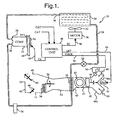
- the reference numeral 10 generally designates a vehicle HVAC system, including a refrigerant compressor 12 coupled to a drive pulley 14 via an electrically activated clutch 16.
- the compressor 12 has a fixed stroke, and the cooling capacity is controlled by cycling the clutch 16.
- the compressor 12 may alternatively be a variable capacity compressor, in which case an electric or pneumatic stroke control valve is used to achieve capacity control.
- the drive pulley 14 is coupled to a rotary shaft of the vehicle engine (not shown) via drive belt 18.
- the system 10 further includes a condenser 20, an orifice tube 22, an evaporator 24, and an accumulator/dehydrator 26 arranged in order between the compressor discharge port 28 and suction port 30.
- a cooling fan 32 operated by an electric drive motor 34, is controlled to provide supplemental air flow through the condenser 20 for removing heat from condenser 20.
- the orifice tube 22 allows the cooled high pressure refrigerant in line 38 to expand in an isenthalpic process before passing through the evaporator 24.
- the accumulator/dehydrator 26 separates low pressure gaseous and liquid refrigerant, directs a gaseous portion to the compressor suction port 30, and acts as a reservoir for the reserve refrigerant charge.
- the orifice tube 22 is replaced with a thermostatic expansion valve (TXV); in this case, the accumulator/ dehydrator 26 is omitted, and a receiver/drier (R/D) is inserted in line 38 upstream of the TXV to ensure that sub-cooled liquid refrigerant is supplied to the inlet of the TXV.
- TXV thermostatic expansion valve
- R/D receiver/drier
- the evaporator 24 is formed as an array of finned refrigerant conducting tubes, and an air intake duct 40 disposed on one side of evaporator 24 houses an air filter 41 and an inlet air blower 42 driven by an electric blower motor 43 to force the inlet air past the filter 41 and evaporator 24.
- the air intake duct 40 is bifurcated upstream of the filter 41 and blower 42, and an inlet air valve 44 is adjustable as shown by the servo motor (SM) 46 to control inlet air mixing.
- SM servo motor
- the air inlet valve 44 is considered to be closed when the leg 44a is fully restricted, and the inlet air consists essentially of cabin air from the leg 44b; conversely, the air inlet valve 44 is considered to be open when the leg 44b is fully restricted, and the inlet air consists essentially of outside air from the leg 44a.
- An air outlet duct 52 disposed on the downstream side of blower 42 and evaporator 24 houses a heater core 54 formed as an array of finned tubes that conduct engine coolant.
- the heater core 54 effectively bifurcates the outlet duct 52, and a re-heat valve 56 is adjustable as shown to control how much of the air must pass through the heater core 54.
- the heated and un-heated air portions are mixed in a plenum portion 62 of outlet duct 52 downstream of re-heat valve 56, and a pair of mode control valves 64, 66 direct the mixed air through one or more outlets, including a defrost outlet 68, a panel outlet 70, and a heater outlet 72.
- the mode control valve 64 is adjustable as shown to switch the outlet air between the defrost and panel outlets 68, 70, and the mode control valve 66 is adjustable as shown to control airflow through the heater outlet 72.
- the system 10 is controlled by the microprocessor-based control unit 90 based on various inputs.
- such inputs include: cabin air temperature CAT, the outside air temperature OAT, outside air quality level OAQL, and the usual operator demand inputs, such as the desired temperature, and override controls for the inlet air valve 44.
- the CAT and OAT signals are obtained with conventional temperature sensors (not shown), and the OAQL signal is provided by the air quality sensor 92.
- the air quality sensor 92 is mounted on the outside air inlet leg 44a as indicated, and its OAQL output signal on line 94 provides an indication of the level of pollutants in the inlet leg 44a.
- the sensor 92 may be a Paragon MK IV air quality sensor, available from Paragon AG, in which case the output OAQL assumes one of four possible voltage levels following an initial warm-up period: a first voltage level for clean (i.e., unpolluted) air, and second, third and fourth levels for increasingly polluted air.
- a first voltage level for clean (i.e., unpolluted) air i.e., unpolluted
- second, third and fourth levels for increasingly polluted air.
- the control unit 90 develops output signals for controlling the compressor clutch 16, the cooling blower motor 34, the blower motor 43, and the air control valves 44, 56, 64 and 66.
- the output signal CL for the clutch 16 appears on line 96
- the output signal FC for the condenser fan control appears on line 98.
- the output signal IAV for positioning the inlet air valve 44 appears on line 99, and is applied as an input to the servo motor 46, which in turn, is mechanically coupled to inlet air valve 44 as mentioned above.
- output signals and actuators for the blower motor 43 and the air control valves 56, 64, 66 have been omitted in Figure 1 .
- the control unit 90 regulates the position of inlet air valve 44 in response to the outside air quality level signal OAQL so as to minimize the admission of polluted air into the inlet air stream.
- OAQL signal indicates the presence of polluted air in inlet leg 44a
- the control unit 90 quickly closes the air inlet valve 44 to provide full cabin air recirculation.
- the control unit 90 re-opens the inlet air valve 44 at a determined rate. The re-opening rate is determined based on the indicated pollution level prior to the indication of clean air.
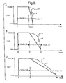
- the different rates for the air quality sensor 92 of the illustrated embodiment are graphically depicted in Figure 3 .
- Each of the Graphs A-C depict an inlet air valve control signal IAV developed by control unit 90 as a function of time.
- Graph A depicts a situation in which the OAQL signal indicates level I air pollution in the time interval t0-t1;
- Graph B depicts a situation in which the OAQL signal indicates level II air pollution in the interval t0-t1; and
- Graph C depicts a situation in which the OAQL signal indicates level III air pollution in the interval t0-t1. So long as the OAQL signal indicates the presence of polluted air, the inlet air valve 44 is maintained closed for full cabin air recirculation (RECIRC) as indicated.
- RECIRC full cabin air recirculation
- the inlet air valve 44 is re-opened (i.e., to full outside air OSA) at a determined rate.
- the indicated pollution level was low (level I), and the control unit 90 re-opens the inlet air valve 44 at a relatively fast rate A that will fully open the valve 44 at time t2, which may be approximately 12 seconds after time t1.
- the indicated pollution level was medium (level II), and the control unit 90 re-opens the inlet air valve 44 at a medium rate B that will fully open the valve 44 at time t3, which may be approximately 30 seconds after time t1.
- the control unit 90 re-opens the inlet air valve 44 at a relatively slow rate C that will fully open the valve 44 at time t4, which may be approximately 60 seconds after time t1.
- the rate of re-opening may be non-linear (exponential, for example) instead of linear, as designated by the broken traces A', B' and C' in Graphs A, B and C, respectively.
- Graphs A and C of Figure 2 illustrate the effect of the above-described control (with linear re-opening rates A, B and C) for a period of driving in stop-and-go city traffic.
- the inlet air valve 44 is re-opened at a rate (A, B or C) corresponding to the indicated pollution level (I, II or III) just prior to receipt of the clean air indication.
- Graph B illustrates a conventional or known control in which the air inlet valve 44 is quickly re-opened each time the OAQL signal indicates the presence of clean air. Comparing Graphs B and C, it is easily seen that the control of the present invention results in significantly less movement of the inlet air valve 44, and testing has shown that the cabin noise level fluctuation under such driving conditions is significantly reduced.
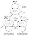
- the state diagram of Figure 4 represents the functionality of a software routine executed by the control unit 90 for carrying out the control of this invention.
- the control unit 90 sets the inlet air valve signal IAV at a minimum value MIN for full outside air (OSA).
- the control unit 90 sets the inlet air valve signal IAV at a maximum value MAX for full cabin air recirculation (RECIRC), and updates a variable OAQL_LAST to store the most recent level of the air quality signal OAQL prior to a transition to the C level.
- state 104 serves to re-open the inlet air valve 44 at a determined rate as described above in respect to Figures 2-3 , and the control unit 90 transitions to the state 106 when IAV has been reduced to the minimum value MIN (for full OSA), provided that OAQL remains at level C. If OAQL transitions from level C to levels I, II or III while the state 104 is active, the control unit 90 will re-enter state 102 as indicated in Figure 4 .
- control of this invention provides a novel and advantageous way of operating an inlet air valve in response to sensed air quality that achieves the objective of minimizing intrusion of polluted air into the vehicle cabin while also minimizing the associated noise level in the cabin. Since the noise fluctuation introduced by the control is less perceptible to the occupants, the driver is less likely to override the control in a way that provides less effective filtering of the cabin air. While described in reference to the illustrated embodiment, it is expected that various modifications in addition to those mentioned above will occur to those skilled in the art. Thus, the control of this invention may be applied to air conditioning systems configured differently than shown in Figure 1 , or to air quality sensors that provide an output that is different than described herein.
- the re-opening rate may be calibrated as a function of the sensor output level to achieve essentially the same operation as depicted in Figures 2-3 . Accordingly, it will be understood that methods incorporating these and other modifications may fall within the invention, which is defined by the appended claims.
Landscapes
- Engineering & Computer Science (AREA)
- Mechanical Engineering (AREA)
- Physics & Mathematics (AREA)
- Thermal Sciences (AREA)
- Life Sciences & Earth Sciences (AREA)
- Atmospheric Sciences (AREA)
- Environmental & Geological Engineering (AREA)
- Air-Conditioning For Vehicles (AREA)
Claims (11)
- Procédé de positionnement d'un clapet d'air aspiré (44) d'un système de chauffage, ventilation et climatisation d'air (10) de véhicule permettant de commander quelle proportion d'air aspiré est tirée de l'extérieur et de l'intérieur d'un habitacle du véhicule, le système comprenant un capteur de la qualité de l'air (92) permettant de détecter un niveau de pollution de l'air à l'extérieur de l'habitacle du véhicule, le procédé comprenant les étapes consistant à : déplacer immédiatement le clapet d'air aspiré jusqu'à une position de recirculation à laquelle l'air aspiré se compose essentiellement d'air provenant de l'intérieur de l'habitacle de véhicule (102) quand le capteur de la qualité de l'air détecte que l'air à l'extérieur de l'habitacle du véhicule est pollué; etdéplacer progressivement le clapet d'air aspiré à une vitesse déterminée jusqu'à une position d'air extérieur à laquelle l'air aspiré se compose essentiellement d'air provenant de l'extérieur de l'habitacle de véhicule quand le capteur de la qualité de l'air détecte que l'air à l'extérieur de l'habitacle du véhicule n'est plus pollué,caractérisé en ce que ladite vitesse déterminée est basée sur le niveau de pollution détecté (104).
- Procédé selon la revendication 1, comprenant l'étape consistant à déplacer progressivement le clapet d'air aspiré jusqu'à ladite position d'air extérieur à une vitesse qui varie selon un rapport inverse au niveau de pollution détecté (104) quand le capteur de la qualité de l'air détecte que l'air à l'extérieur de l'habitacle du véhicule n'est plus pollué
- Procédé selon la revendication 2, où la vitesse déterminée est une vitesse linéaire.
- Procédé selon la revendication 2, où la vitesse déterminée est une vitesse exponentielle.
- Procédé selon la revendication 1, comprenant les étapes consistant à :établir un premier mode de fonctionnement permettant de positionner le clapet d'air aspiré à une première position qui limite l'air aspiré à de l'air provenant essentiellement de l'extérieur de l'habitacle du véhicule quand le capteur de la qualité de l'air détecte de l'air extérieur non pollué (100) ;établir un deuxième mode de fonctionnement permettant de positionner le clapet d'air aspiré à une deuxième position qui limite l'air aspiré à de l'air provenant essentiellement de l'intérieur de l'habitacle du véhicule quand le capteur de la qualité de l'air détecte de l'air extérieur pollué (102) ;établir un troisième mode de fonctionnement permettant de déplacer le clapet d'air aspiré de la deuxième position à la première position à ladite vitesse déterminée quand le capteur de la qualité de l'air détecte un passage de l'air pollué à l'air non pollué (104).
- Procédé selon la revendication 5, comprenant l'étape consistant à passer du troisième mode de fonctionnement au premier mode de fonctionnement quand le clapet d'aspiration d'air atteint ladite première position et que le capteur de la qualité de l'air continue à détecter une non pollution de l'air extérieur (104, 100).
- Procédé selon la revendication 5, comprenant l'étape consistant à passer du troisième mode de fonctionnement au deuxième mode de fonctionnement quand le capteur de la qualité de l'air détecte à nouveau un pollution de l'air extérieur (104, 102).
- Procédé selon la revendication 5, comprenant l'étape consistant à :stocker le niveau de pollution détecté par le capteur de la qualité de l'air au cours dudit deuxième mode de fonctionnement (102) ; etdéterminer la vitesse de déplacement du clapet d'aspiration d'air au cours du troisième mode de fonctionnement basée sur le niveau de pollution stocké (104).
- Procédé selon la revendication 8, comprenant l'étape consistant à mettre à jour ledit niveau de pollution stocké au cours dudit deuxième mode de fonctionnement (102) de telle sorte que la vitesse de déplacement du clapet d'aspiration d'air au cours du troisième mode de fonctionnement soit déterminée sur la base du niveau de pollution détecté juste avant un passage dudit deuxième mode de fonctionnement audit troisième mode de fonctionnement (104).
- Procédé selon la revendication 5, où la vitesse déterminée est une vitesse linéaire.
- Procédé selon la revendication 5, où la vitesse déterminée est une vitesse exponentielle.
Applications Claiming Priority (2)
| Application Number | Priority Date | Filing Date | Title |
|---|---|---|---|
| US369249 | 2003-02-19 | ||
| US10/369,249 US6800022B2 (en) | 2003-02-19 | 2003-02-19 | Inlet air control method for a vehicle HVAC system having an air quality sensor |
Publications (3)
| Publication Number | Publication Date |
|---|---|
| EP1449691A2 EP1449691A2 (fr) | 2004-08-25 |
| EP1449691A3 EP1449691A3 (fr) | 2005-12-28 |
| EP1449691B1 true EP1449691B1 (fr) | 2008-04-16 |
Family
ID=32736421
Family Applications (1)
| Application Number | Title | Priority Date | Filing Date |
|---|---|---|---|
| EP04075352A Expired - Lifetime EP1449691B1 (fr) | 2003-02-19 | 2004-02-03 | Procédé d'admission d'air pour système de conditionnement d'air de véhicule avec un détecteur de la qualité de l'air |
Country Status (3)
| Country | Link |
|---|---|
| US (2) | US6800022B2 (fr) |
| EP (1) | EP1449691B1 (fr) |
| DE (1) | DE602004013065T2 (fr) |
Families Citing this family (28)
| Publication number | Priority date | Publication date | Assignee | Title |
|---|---|---|---|---|
| US8092285B2 (en) * | 2006-03-21 | 2012-01-10 | Calsonickansei North America, Inc. | System and method for controlling a ventilation unit of a vehicle |
| JP5519294B2 (ja) * | 2007-01-10 | 2014-06-11 | コーニンクレッカ フィリップス エヌ ヴェ | 空調システムを制御するための制御システム |
| US20080182506A1 (en) * | 2007-01-29 | 2008-07-31 | Mark Jackson | Method for controlling multiple indoor air quality parameters |
| DE102007015477A1 (de) * | 2007-03-30 | 2008-10-02 | Siemens Ag | Schienenfahrzeug zur Personenbeförderung mit Immissionsschutz |
| DE102007018571A1 (de) * | 2007-04-18 | 2008-10-23 | Robert Bosch Gmbh | Vorrichtung zur Steuerung der Belüftungseinrichtung für einen Kraftfahrzeuginnenraum |
| US7637031B2 (en) * | 2007-06-26 | 2009-12-29 | Gm Global Technology Operations, Inc. | Evaporator core drying system |
| DE102007048682A1 (de) * | 2007-10-10 | 2009-04-16 | Volkswagen Ag | Luftaufbereitungsanordnung und Verfahren zur Aufbereitung der Luft im Innenraum eines Kraftfahrzeugs |
| FR2934815B1 (fr) * | 2008-08-07 | 2010-09-03 | Valeo Systemes Thermiques | Boitier d'entree d'air comprenant des moyens d'attenuation de nuisances acoustiques |
| GB0822586D0 (en) * | 2008-12-11 | 2009-01-14 | Agco Gmbh | Tractor cab heating and ventilating systems |
| DE102010026101B4 (de) * | 2010-07-05 | 2018-06-28 | Audi Ag | Heizungs- und Klimatisierungseinrichtung |
| JP5005073B2 (ja) * | 2010-07-20 | 2012-08-22 | 本田技研工業株式会社 | 車両のシャッタ装置 |
| DE102013214071A1 (de) * | 2013-07-19 | 2015-01-22 | Bayerische Motoren Werke Aktiengesellschaft | Verfahren zum Steuern einer Lüftungs-/Klimaanlage eines Fahrzeugs sowie Fahrzeug mit einer derartigen Lüftungs-/Klimaanlage |
| KR20160024536A (ko) * | 2014-08-26 | 2016-03-07 | 기아자동차주식회사 | 차량 내부 공기 정화를 위한 텔레매틱스 단말 및 그 제어 방법 |
| US10058013B2 (en) * | 2015-01-06 | 2018-08-21 | Dell Products, L.P. | Environment-controlled cooling mode selection for a modular data center based on detection of contaminants and particulates in outside air |
| US10226982B2 (en) * | 2015-04-29 | 2019-03-12 | International Business Machines Corporation | Automatic vehicle climate control based on predicted air quality |
| US9682610B2 (en) | 2015-10-20 | 2017-06-20 | International Business Machines Corporation | Intelligent automotive air-quality assessment and management |
| US11034212B2 (en) | 2016-03-01 | 2021-06-15 | GM Global Technology Operations LLC | Systems and methods for cabin air quality control |
| DE102017220350A1 (de) | 2016-12-06 | 2018-06-07 | Mahle International Gmbh | Verfahren zum Betreiben einer Belüftungseinrichtung eines Fahrzeugs |
| CN108266931B (zh) * | 2016-12-30 | 2022-02-11 | 杭州三花研究院有限公司 | 一种热管理系统及其控制方法 |
| KR20180112533A (ko) * | 2017-04-04 | 2018-10-12 | 현대자동차주식회사 | 차량의 실내 공기질 개선 장치 |
| DE102019110590A1 (de) * | 2019-04-24 | 2020-10-29 | HELLA GmbH & Co. KGaA | Sensorvorrichtung zur Untersuchung eines Probengasvolumens |
| US11604004B2 (en) | 2019-12-26 | 2023-03-14 | Prakash SAVAKKANAVAR | Method and system to measure and control indoor environment using IoT and AI |
| KR102331353B1 (ko) * | 2019-12-31 | 2021-11-25 | 솔라시도코리아 주식회사 | 공조형 공기청정 장치 |
| DE102020101741A1 (de) * | 2020-01-24 | 2021-07-29 | Ford Global Technologies, Llc | Verfahren zur Bestimmung der Luftqualität in einem Fahrgastraum eines Kraftfahrzeugs |
| KR102188972B1 (ko) * | 2020-04-06 | 2020-12-10 | 원태연 | 창문 장착형 스마트 환기청정기 |
| US11703818B2 (en) | 2020-08-03 | 2023-07-18 | Trane International Inc. | Systems and methods for indoor air quality based on dynamic people modeling to simulate or monitor airflow impact on pathogen spread in an indoor space and to model an indoor space with pathogen killing technology, and systems and methods to control administration of a pathogen killing technology |
| US12011971B2 (en) * | 2021-07-20 | 2024-06-18 | Rivian Ip Holdings, Llc | Automatic air intake sealing |
| US12017508B2 (en) | 2021-09-02 | 2024-06-25 | Apple Inc. | Climate control system |
Family Cites Families (12)
| Publication number | Priority date | Publication date | Assignee | Title |
|---|---|---|---|---|
| US5946923A (en) * | 1987-02-06 | 1999-09-07 | Denso Corporation | Air conditioning system for vehicle |
| DE4106078A1 (de) * | 1991-02-27 | 1992-09-03 | Daimler Benz Ag | Vorrichtung bzw. verfahren zur steuerung der belueftung eines innenraumes, insbesondere bei kraftfahrzeugen |
| DE4436938A1 (de) | 1994-04-27 | 1996-04-18 | Auto Electronics Corp | Nässe- und windgeschützter Gassensor |
| DE19619553B4 (de) * | 1996-05-15 | 2008-07-17 | Paragon Ag | Schaltungsanordnung und Verfahren zur schadstoffgesteuerten Belüftung einer Fahrzeugkabine |
| DE19637232A1 (de) * | 1996-09-13 | 1998-03-19 | Behr Gmbh & Co | Vorrichtung und Verfahren zur Steuerung von Luftführungselementen eines Fahrzeugs |
| DE19720293C1 (de) * | 1997-05-15 | 1998-06-04 | Daimler Benz Ag | Vorrichtung und Verfahren zur schadgasabhängigen Fahrzeuginnenraumbelüftung |
| JP3508485B2 (ja) * | 1997-07-17 | 2004-03-22 | 株式会社デンソー | 車両用空調装置 |
| US6239115B1 (en) * | 1997-11-17 | 2001-05-29 | Kaken Pharmaceutical Co., Ltd. | Dry flowable polyoxin compositions |
| US6298291B1 (en) * | 1999-12-22 | 2001-10-02 | Visteon Global Technologies, Inc. | Method of establishing baseline filter for air quality |
| US6293115B1 (en) * | 2000-04-10 | 2001-09-25 | Delphi Technologies, Inc. | Inlet air mixture control method for a vehicle air conditioning system |
| US6367281B1 (en) * | 2000-05-25 | 2002-04-09 | Jason James Hugenroth | Solid phase change refrigeration |
| US6508408B2 (en) * | 2001-05-08 | 2003-01-21 | Delphi Technologies, Inc. | Automatic windglass fog prevention method for a vehicle climate control system |
-
2003
- 2003-02-19 US US10/369,249 patent/US6800022B2/en not_active Expired - Fee Related
-
2004
- 2004-02-03 EP EP04075352A patent/EP1449691B1/fr not_active Expired - Lifetime
- 2004-02-03 DE DE602004013065T patent/DE602004013065T2/de not_active Expired - Lifetime
- 2004-10-13 US US10/963,445 patent/US20050095971A1/en not_active Abandoned
Also Published As
| Publication number | Publication date |
|---|---|
| US6800022B2 (en) | 2004-10-05 |
| DE602004013065T2 (de) | 2009-06-25 |
| US20050095971A1 (en) | 2005-05-05 |
| US20040162016A1 (en) | 2004-08-19 |
| EP1449691A3 (fr) | 2005-12-28 |
| DE602004013065D1 (de) | 2008-05-29 |
| EP1449691A2 (fr) | 2004-08-25 |
Similar Documents
| Publication | Publication Date | Title |
|---|---|---|
| EP1449691B1 (fr) | Procédé d'admission d'air pour système de conditionnement d'air de véhicule avec un détecteur de la qualité de l'air | |
| US5681218A (en) | Air conditioning system for vehicles | |
| DE60201101T2 (de) | Verfahren für Kraftfahrzeugklimaanlage zur Verhinderung des Kondensierens von Feuchtigkeit auf der Windschutzscheibe | |
| EP0396017B1 (fr) | Appareil de refroidissement de l'air pour véhicule | |
| US6009934A (en) | Electronic climate control system for automotive vehicles | |
| US20060225450A1 (en) | Hybrid-electric vehicle with automatic climate control strategy | |
| EP0287393A2 (fr) | Dispositif de commande pour système de conditionnement d'air de véhicule | |
| US5983649A (en) | System and method for prevention of windshield fogging in a motor vehicle | |
| US6640564B2 (en) | Vehicle air conditioner with automatic breaking-in operation of compressor | |
| JP2007131232A (ja) | 車両用空調制御装置 | |
| JP3085329B2 (ja) | 車両用空気調和装置 | |
| US11427049B2 (en) | Vehicle air conditioner | |
| JP4331532B2 (ja) | 自動車用空調装置 | |
| JPS6189113A (ja) | 車両用空調装置 | |
| US6134895A (en) | Method of air conditioning system temperature control | |
| KR101105028B1 (ko) | 자동차용 공조장치의 제어방법 | |
| KR100928000B1 (ko) | 자동차용 공기조화장치의 난방 제어방법 | |
| JP4370562B2 (ja) | 車両用空気調和装置 | |
| JPH0622566Y2 (ja) | 車両用空調装置のデミスト制御装置 | |
| JPH0727254Y2 (ja) | 自動車用空調装置のデミスト制御装置 | |
| JP3572678B2 (ja) | 車両用空調装置 | |
| JPH0538929A (ja) | 車両用空気調和装置 | |
| JPH08183329A (ja) | 車両用空調装置 | |
| JPH0427616A (ja) | ブロアファンの吸込口切換制御装置 | |
| JPH0891040A (ja) | 電気自動車用空調装置 |
Legal Events
| Date | Code | Title | Description |
|---|---|---|---|
| PUAI | Public reference made under article 153(3) epc to a published international application that has entered the european phase |
Free format text: ORIGINAL CODE: 0009012 |
|
| AK | Designated contracting states |
Kind code of ref document: A2 Designated state(s): AT BE BG CH CY CZ DE DK EE ES FI FR GB GR HU IE IT LI LU MC NL PT RO SE SI SK TR |
|
| AX | Request for extension of the european patent |
Extension state: AL LT LV MK |
|
| PUAL | Search report despatched |
Free format text: ORIGINAL CODE: 0009013 |
|
| AK | Designated contracting states |
Kind code of ref document: A3 Designated state(s): AT BE BG CH CY CZ DE DK EE ES FI FR GB GR HU IE IT LI LU MC NL PT RO SE SI SK TR |
|
| AX | Request for extension of the european patent |
Extension state: AL LT LV MK |
|
| 17P | Request for examination filed |
Effective date: 20060628 |
|
| AKX | Designation fees paid |
Designated state(s): DE FR GB |
|
| 17Q | First examination report despatched |
Effective date: 20060816 |
|
| GRAP | Despatch of communication of intention to grant a patent |
Free format text: ORIGINAL CODE: EPIDOSNIGR1 |
|
| GRAS | Grant fee paid |
Free format text: ORIGINAL CODE: EPIDOSNIGR3 |
|
| GRAA | (expected) grant |
Free format text: ORIGINAL CODE: 0009210 |
|
| AK | Designated contracting states |
Kind code of ref document: B1 Designated state(s): DE FR GB |
|
| REF | Corresponds to: |
Ref document number: 602004013065 Country of ref document: DE Date of ref document: 20080529 Kind code of ref document: P |
|
| ET | Fr: translation filed | ||
| PLBE | No opposition filed within time limit |
Free format text: ORIGINAL CODE: 0009261 |
|
| STAA | Information on the status of an ep patent application or granted ep patent |
Free format text: STATUS: NO OPPOSITION FILED WITHIN TIME LIMIT |
|
| 26N | No opposition filed |
Effective date: 20090119 |
|
| PGFP | Annual fee paid to national office [announced via postgrant information from national office to epo] |
Ref country code: FR Payment date: 20100223 Year of fee payment: 7 |
|
| PGFP | Annual fee paid to national office [announced via postgrant information from national office to epo] |
Ref country code: DE Payment date: 20100211 Year of fee payment: 7 Ref country code: GB Payment date: 20100202 Year of fee payment: 7 |
|
| GBPC | Gb: european patent ceased through non-payment of renewal fee |
Effective date: 20110203 |
|
| REG | Reference to a national code |
Ref country code: FR Ref legal event code: ST Effective date: 20111102 |
|
| REG | Reference to a national code |
Ref country code: DE Ref legal event code: R119 Ref document number: 602004013065 Country of ref document: DE Effective date: 20110901 |
|
| PG25 | Lapsed in a contracting state [announced via postgrant information from national office to epo] |
Ref country code: FR Free format text: LAPSE BECAUSE OF NON-PAYMENT OF DUE FEES Effective date: 20110228 |
|
| PG25 | Lapsed in a contracting state [announced via postgrant information from national office to epo] |
Ref country code: GB Free format text: LAPSE BECAUSE OF NON-PAYMENT OF DUE FEES Effective date: 20110203 |
|
| PG25 | Lapsed in a contracting state [announced via postgrant information from national office to epo] |
Ref country code: DE Free format text: LAPSE BECAUSE OF NON-PAYMENT OF DUE FEES Effective date: 20110901 |