EP1445377A1 - Breitnip-Kalander - Google Patents
Breitnip-Kalander Download PDFInfo
- Publication number
- EP1445377A1 EP1445377A1 EP03027128A EP03027128A EP1445377A1 EP 1445377 A1 EP1445377 A1 EP 1445377A1 EP 03027128 A EP03027128 A EP 03027128A EP 03027128 A EP03027128 A EP 03027128A EP 1445377 A1 EP1445377 A1 EP 1445377A1
- Authority
- EP
- European Patent Office
- Prior art keywords
- fibrous web
- dust
- dust removal
- jacket
- removal device
- Prior art date
- Legal status (The legal status is an assumption and is not a legal conclusion. Google has not performed a legal analysis and makes no representation as to the accuracy of the status listed.)
- Granted
Links
- 239000000428 dust Substances 0.000 claims abstract description 65
- 238000004140 cleaning Methods 0.000 claims description 16
- 239000002245 particle Substances 0.000 description 9
- 230000007423 decrease Effects 0.000 description 3
- 239000011111 cardboard Substances 0.000 description 2
- 238000010438 heat treatment Methods 0.000 description 2
- 239000000463 material Substances 0.000 description 2
- 239000011087 paperboard Substances 0.000 description 2
- 239000004753 textile Substances 0.000 description 2
- 239000003795 chemical substances by application Substances 0.000 description 1
- 230000006866 deterioration Effects 0.000 description 1
- 239000000835 fiber Substances 0.000 description 1
- 230000002706 hydrostatic effect Effects 0.000 description 1
- 238000005461 lubrication Methods 0.000 description 1
- 239000000203 mixture Substances 0.000 description 1
- 239000000123 paper Substances 0.000 description 1
Images
Classifications
-
- D—TEXTILES; PAPER
- D21—PAPER-MAKING; PRODUCTION OF CELLULOSE
- D21G—CALENDERS; ACCESSORIES FOR PAPER-MAKING MACHINES
- D21G1/00—Calenders; Smoothing apparatus
- D21G1/006—Calenders; Smoothing apparatus with extended nips
Definitions
- the invention relates to a wide nip calender with a a surrounding jacket and a pressure shoe having a shoe roller and a counter pressure element, which together form a wide nip, through which a web running path a fibrous web runs.
- a wide nip calender is used to make a fibrous web, for example a paper or cardboard web, with increased pressure and usually also with an increased Temperature.
- the Breitnip calender compared to a calender by two against each other acting rollers is formed, the advantage that the treatment time of the fibrous web is longer, the Compressive stresses in the wide nip are kept smaller can than in a nip between two rollers.
- the thickness of the fibrous web is not reduced as much in the wide nip as in one Nip between two rollers.
- the invention has for its object the quality maintain the fibrous web over a longer period of time.
- This task is the beginning of a wide nip calender mentioned type in that at the exit of the Breitnips arranged a dust removal device is.
- the deterioration in the quality of the fibrous web is carried out due to the fact that the relative movement or shear forces in the Breitnip particles from the surface remove the fibrous web. These particles result corresponding dust deposits on the jacket. Dust deposits on the coat lead to a change the surface of the mantle, which negatively affects the quality of the fibrous web, especially on the Quality of the surface, can impact. Furthermore there will certainly be some dust particles on the Surface of the fibrous web remain, which then deposit in downstream facilities and close there lead to increasing pollution. Pollution in downstream facilities can also cause the quality of the surface of the fibrous web decreases. With these facilities it can are, in the simplest case, deflection rollers, via which the fibrous web is guided.
- the dust removal device is preferably between the fibrous web and the jacket arranged. you assumes that most of the dust comes from the relative movement between the fibrous web and the jacket arises. This may be because the back pressure element, usually as a roller, especially is designed as a heating roller, a smoother surface with less particles from the surface the fibrous web are detached. The most Dust therefore arises between the jacket and the fibrous web. If you look at the dust removal device Arranged here, then most of the dust will be removed become.
- the dust removal device preferably has a Suction device on.
- the dust removal device works according to the classic principle of one "Vacuum cleaner", in which a part of the dust that is on Output of the wide nip is present, can be suctioned off can.
- the suction device is a a gusset between the fibrous web and the jacket has directed suction nozzle element. So you can start sucking shortly after the fibrous web detached from the coat. In this case the distance between the jacket and the fibrous web still relatively small. Accordingly, it can be assumed that the "dust density" in this area is still relative is great. By separating the fibrous web and Dust is whirled up, i.e. at least one Part of the dust is in the air where it is can be easily vacuumed.
- the suction nozzle element preferably has one of the First wall facing the fibrous web and one facing the jacket facing second wall, with at least one Wall several suction openings are provided. This Suction openings are then directed onto a surface of where the dust can be extracted with increased intensity can.
- a surface cleaning arrangement on the fibrous web and / or on the jacket is arranged.
- a surface cleaning arrangement is able to remove dust, that sticks to a surface.
- the surface cleaning arrangement has a mechanical dust removal device.
- the mechanical dust removal device is able to loosen the dust from the surface to be cleaned. As soon as the dust is detached from the surface to be cleaned has been, for example, via the suction device be removed. Of course it is also possible to provide additional dust removal agents.
- the dust removal device has a compressed air jet.
- a jet of compressed air that hits the surface of the Fibrous web or is directed to the jacket able to peel off a dust deposit, so to speak. The stress on the fibrous web or the jacket stays small.
- the dust removal device is a relative to the cleaning surface has a movable brush.
- the brush then really brushes the fibrous web or the jacket from.
- a brush of course, another one Element that can be used on the surface the fibrous web or the jacket is present, for example a wiping element made of a textile material.
- the dust removal device has a suction device.
- a suction device can together with the compressed air jet or the brush can be used. With the suction device the dust detached from other elements is removed. Under certain circumstances, however, the suction device also capable of being alone on the surface of the fibrous web or adhering to the surface of the jacket To remove dust.
- the surface cleaning arrangement preferably has a Ionization device on. With the help of the ionization device you can get an electrostatic discharge reach the fibrous web or the roll surface, so that the holding forces of the dust on the respective Surface can be reduced.
- the ionization device arranged in the web running direction in front of the dust removal device is. So the holding forces are first reduced between the dust and the surface to be cleaned and then removes the dust using mechanical Means.
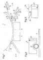
- a wide nip calender 1 has a shoe roller 2 a circumferential jacket 3 and a pressure shoe 4.
- the Sheath 3 works together with a counter pressure element 5, in the present case as a roller, namely as a thermal roller, is trained.
- the counter pressure element 5 is with a heating device, not shown, heated.
- the shoe roller 2 is here with a relatively thick jacket 3, which rotates in the manner of a roller and usually with face washers on its faces is completed. But it is also possible to use the coat 3 run thinner and like a tape over to run several support rollers.
- the pressure shoe 4 has a pressure surface 6, the essentially adapted to the curvature of the counter-pressure element is, of course, the thickness of the jacket 3 is taken into account must become.
- An exact match between the curvature of the pressure surface 6 and the curvature of the counter-pressure element 5 is usually not mandatory.
- the pressure surface 6 can devices for reducing in a manner known per se a friction between the jacket 3 and the pressure shoe 4 may be provided, for example outlet nozzles hydrostatic lubrication.
- the jacket 3 forms together with the counter pressure element 5 a wide nip 7 through which a fibrous web 8, for example, a paper or cardboard web becomes.
- a fibrous web 8 for example, a paper or cardboard web becomes.
- the fibrous web 8 is increased Pressure and also at elevated temperature.
- the treatment time of the fibrous web 8 in Breitnip 7 depends on the length of the Breitnips 7 in the direction of travel of the web, represented by an arrow 9 is.
- exit 10 is the Wide nips 7 a dust removal device 11 arranged.
- the dust removal device is in the opening gusset between the fibrous web 8 and the jacket 3 arranged. It is believed that Counter pressure element 5, the surface of which is much smoother than the surface of the shell 3 is less dust arises.
- the dust removal device 11 initially has one Suction device 12, which in the opening Gusset between the fibrous web 8 and the jacket 3 is directed at the exit of the wide nip 7.
- the suction device has a wedge-shaped suction nozzle element 13 on.
- the suction nozzle element 13 has one of the fibrous web 8 facing first wall 14 and a jacket 3 facing wall 15.
- There are suction openings in the first wall 16 provided.
- the suction openings 16 suck Dust from the surface of the fibrous web 8 is "whirled up", so after leaving the Breitnips 7 is in the air at the exit of the Breitnips 10.
- the suction openings 17 suck in a similar manner in the second wall 15 the dust coming from the surface of the jacket 3 is whirled up.
- the surface cleaning device 18 has an ionization device 20 with which the surface of the jacket 3 is electrical can be discharged. This creates holding forces between Dust and coat 3 reduced.
- the ionization device 20 is a mechanical dust removal device 21.
- the dust removal device 21 is shown enlarged in Fig. 2. She assigns one circumferential brush 22. Instead of a rotating one Brush 22 you can also use a rotating roller, which is covered with a textile material, and that wipes the surface of the jacket. Behind brush 23, a suction device 23 is provided, which with Using the brush 23 from the surface of the jacket 3 loosened dust.
- the surface cleaning device 19 also has one Ionization electrode 20, with the help of the fibrous web 8 can be discharged electrically to holding forces between the dust and the fibrous web 8 decrease.
- the ionization device 20 is the ionization device 20 but optional, i.e. it is only used when required is.
- the surface cleaning device 19 for the fibrous web 8 also has a mechanical removal device 24, which is shown enlarged in FIG. 3.
- the removal device 24 has an air nozzle 25, against a sharp jet of air 26 from compressed air aligns the surface of the fibrous web 8 and thereby Dust, which lies on the surface of the fibrous web 8, peels off, in particular peels off.
- Suction device 27 available, with the help of detached dust can be extracted.
- the two removal devices 21, 24 are thus as Surface cleaning arrangements formed, which over extend the entire width of the fibrous web 8. The the same also applies to the suction device 12.
- the surface will also suffice of the jacket 3 and / or the surface of the fibrous web 8 only suction, with a vacuum is built in the immediate vicinity of the surface.
- Such a vacuum is also capable of dust mechanically detach from the respective surface. This is especially true if the surface is previously has been electrically discharged.
Landscapes
- Cleaning In General (AREA)
- Paper (AREA)
- Prostheses (AREA)
- Orthopedics, Nursing, And Contraception (AREA)
- Absorbent Articles And Supports Therefor (AREA)
Abstract
Description
- Fig. 1
- eine schematische Seitenansicht eines Breitnip-Kalanders,
- Fig. 2
- eine erste Ausführungsform einer Staubabtrageinrichtung und
- Fig. 3
- eine zweite Ausführungsform einer Staubabtrageinrichtung.
Claims (12)
- Breitnip-Kalander mit einer einen umlaufenden Mantel und einen Anpressschuh aufweisenden Schuhwalze und einem Gegendruckelement, die zusammen einen Breitnip bilden, durch den ein Bahnlaufpfad einer Faserstoffbahn verläuft, dadurch gekennzeichnet, daß am Ausgang (10) des Breitnips (7) eine Staubentfernungseinrichtung (11) angeordnet ist.
- Kalander nach Anspruch 1, dadurch gekennzeichnet, daß die Staubentfernungseinrichtung (11) zwischen der Faserstoffbahn (8) und dem Mantel (3) angeordnet ist.
- Kalander nach Anspruch 1 oder 2, dadurch gekennzeichnet, daß die Staubentfernungseinrichtung (11) eine Absaugeinrichtung (12) aufweist.
- Kalander nach Anspruch 3, dadurch gekennzeichnet, daß die Absaugeinrichtung (12) ein in einen Zwikkel zwischen der Faserstoffbahn (8) und dem Mantel (3) gerichtetes Saugdüsenelement (13) aufweist.
- Kalander nach Anspruch 4, dadurch gekennzeichnet, daß das Saugdüsenelement (13) eine der Faserstoffbahn (8) zugewandte erste Wand (14) und eine dem Mantel (3) zugewandte zweite Wand (15) aufweist, wobei in mindestens einer Wand (14, 15) mehrere Saugöffnungen (16, 17) vorgesehen sind.
- Kalander nach einem der Ansprüche 1 bis 5, dadurch gekennzeichnet, daß an der Faserstoffbahn (8) und/oder am Mantel (3) eine Flächenreinigungsanordnung (18, 19) angeordnet ist.
- Kalander nach Anspruch 6, dadurch gekennzeichnet, daß die Flächenreinigungsanordnung (18, 19) eine mechanische Staubabtrageinrichtung (21, 24) aufweist.
- Kalander nach Anspruch 7, dadurch gekennzeichnet, daß die Staubabtrageinrichtung (24) einen Druckluftstrahl (26) aufweist.
- Kalander nach Anspruch 7 oder 8, dadurch gekennzeichnet, daß die Staubabtrageinrichtung (21) eine relativ zu der zu reinigenden Fläche bewegbare Bürste (22) aufweist.
- Kalander nach einem der Ansprüche 7 bis 9, dadurch gekennzeichnet, daß die Staubabtrageinrichtung (21, 24) eine Saugeinrichtung (23, 27) aufweist.
- Kalander nach einem der Ansprüche 7 bis 10, dadurch gekennzeichnet, daß die Flächenreinigungsanordnung (18, 19) eine Ionisationseinrichtung (20) aufweist.
- Kalander nach Anspruch 11, dadurch gekennzeichnet, daß die Ionisationseinrichtung (20) in Bahnlaufrichtung (9) vor der Staubabtrageinrichtung (21, 24) angeordnet ist.
Applications Claiming Priority (2)
| Application Number | Priority Date | Filing Date | Title |
|---|---|---|---|
| DE20300919U DE20300919U1 (de) | 2003-01-22 | 2003-01-22 | Breitnip-Kalander |
| DE20300919U | 2003-01-22 |
Publications (2)
| Publication Number | Publication Date |
|---|---|
| EP1445377A1 true EP1445377A1 (de) | 2004-08-11 |
| EP1445377B1 EP1445377B1 (de) | 2007-11-14 |
Family
ID=7979290
Family Applications (1)
| Application Number | Title | Priority Date | Filing Date |
|---|---|---|---|
| EP03027128A Expired - Lifetime EP1445377B1 (de) | 2003-01-22 | 2003-11-26 | Breitnip-Kalander |
Country Status (3)
| Country | Link |
|---|---|
| EP (1) | EP1445377B1 (de) |
| AT (1) | ATE378467T1 (de) |
| DE (2) | DE20300919U1 (de) |
Cited By (2)
| Publication number | Priority date | Publication date | Assignee | Title |
|---|---|---|---|---|
| EP1772889A2 (de) | 2005-10-06 | 2007-04-11 | LG Electronics Inc. | Plasmaanzeigevorrichtung |
| CN108951264A (zh) * | 2018-07-12 | 2018-12-07 | 太仓怡泰霖智能科技有限公司 | 一种造纸软压光机 |
Families Citing this family (3)
| Publication number | Priority date | Publication date | Assignee | Title |
|---|---|---|---|---|
| DE20300919U1 (de) * | 2003-01-22 | 2003-04-03 | Voith Paper Patent GmbH, 89522 Heidenheim | Breitnip-Kalander |
| DE102007022810A1 (de) * | 2007-05-15 | 2008-11-20 | Voith Patent Gmbh | Reinigungsverfahren |
| FR2946501B1 (fr) * | 2009-06-11 | 2011-08-12 | Boulangerie Patisserie Felix Fabrice | Dispositif de nettoyage d'une toile a couche |
Citations (5)
| Publication number | Priority date | Publication date | Assignee | Title |
|---|---|---|---|---|
| GB1127897A (en) * | 1965-03-10 | 1968-09-18 | Kuesters Eduard | Improvements in or relating to calenders |
| WO1997031151A1 (en) * | 1996-02-22 | 1997-08-28 | Valmet Corporation | Method and device in a paper machine or equivalent or in a finishing device of same for collecting and removing the dust separated from the web |
| US6148831A (en) * | 1996-10-25 | 2000-11-21 | Valmet Corporation | Method for cleaning a web |
| US6164198A (en) * | 1998-12-16 | 2000-12-26 | Valmet Corporation | Apparatus for calendering paper |
| DE20300919U1 (de) * | 2003-01-22 | 2003-04-03 | Voith Paper Patent GmbH, 89522 Heidenheim | Breitnip-Kalander |
-
2003
- 2003-01-22 DE DE20300919U patent/DE20300919U1/de not_active Expired - Lifetime
- 2003-11-26 DE DE50308594T patent/DE50308594D1/de not_active Expired - Lifetime
- 2003-11-26 AT AT03027128T patent/ATE378467T1/de active
- 2003-11-26 EP EP03027128A patent/EP1445377B1/de not_active Expired - Lifetime
Patent Citations (5)
| Publication number | Priority date | Publication date | Assignee | Title |
|---|---|---|---|---|
| GB1127897A (en) * | 1965-03-10 | 1968-09-18 | Kuesters Eduard | Improvements in or relating to calenders |
| WO1997031151A1 (en) * | 1996-02-22 | 1997-08-28 | Valmet Corporation | Method and device in a paper machine or equivalent or in a finishing device of same for collecting and removing the dust separated from the web |
| US6148831A (en) * | 1996-10-25 | 2000-11-21 | Valmet Corporation | Method for cleaning a web |
| US6164198A (en) * | 1998-12-16 | 2000-12-26 | Valmet Corporation | Apparatus for calendering paper |
| DE20300919U1 (de) * | 2003-01-22 | 2003-04-03 | Voith Paper Patent GmbH, 89522 Heidenheim | Breitnip-Kalander |
Cited By (2)
| Publication number | Priority date | Publication date | Assignee | Title |
|---|---|---|---|---|
| EP1772889A2 (de) | 2005-10-06 | 2007-04-11 | LG Electronics Inc. | Plasmaanzeigevorrichtung |
| CN108951264A (zh) * | 2018-07-12 | 2018-12-07 | 太仓怡泰霖智能科技有限公司 | 一种造纸软压光机 |
Also Published As
| Publication number | Publication date |
|---|---|
| EP1445377B1 (de) | 2007-11-14 |
| DE20300919U1 (de) | 2003-04-03 |
| DE50308594D1 (de) | 2007-12-27 |
| ATE378467T1 (de) | 2007-11-15 |
Similar Documents
| Publication | Publication Date | Title |
|---|---|---|
| DE4018074C2 (de) | Vorrichtung zum Reinigen eines umlaufenden Papiermaschinensiebes | |
| EP0731212B1 (de) | Reinigungsvorrichtung | |
| DE19702196C5 (de) | Vorrichtung zum Reinigen eines Transportbandes | |
| DE3346092A1 (de) | Krempel und krempelverfahren | |
| DE10050974A1 (de) | Abstreifer für eine Walze | |
| DE19539015A1 (de) | Reinigungsvorrichtung | |
| DE2634770B2 (de) | Vorrichtung zum Abführen von Verunreinigungen bei einer OE-Spinnmaschine mit mehreren Spinnstellen | |
| EP0817884B1 (de) | Reinigungsvorrichtung | |
| EP1445377B1 (de) | Breitnip-Kalander | |
| DE3400939C2 (de) | ||
| EP0522093A1 (de) | Verfahren und vorrichtung zum reinigen eines umlaufenden papiermaschinensiebes | |
| DE4402279C2 (de) | Verfahren und Vorrichtung zum Reinigen eines umlaufenden Papiermaschinensiebes | |
| EP1884588A2 (de) | Reinigungsvorrichtung | |
| EP3665318A1 (de) | Karde | |
| DE1710043A1 (de) | Vorrichtung zum kontinuierlichen ringlosen Feinspinnen von Textilfaser mit einer einen Saugeffekt ausloesenden rotierenden Spinnkammer | |
| DE3800669C2 (de) | ||
| DE19782108B4 (de) | Verfahren zum Entfernen von Staub in der Schneidepartie einer Zellstofftrockenmaschine und Vorrichtung zur Durchführung des Verfahrens | |
| DE102005052858A1 (de) | Reinigungssystem | |
| WO2002078956A1 (de) | Vorrichtung zur reinigung der oberfläche(n) einer bewegten materialbahn | |
| DE4122596A1 (de) | Vorrichtung zur voraufloesung, reinigung und zerfaserung von fasermaterial | |
| EP0106969B1 (de) | Vorrichtung zum Scheren von Stoffbahnen | |
| DE2509020C3 (de) | Vorrichtung zum Abtrennen einer Papierbahn vom Langsieb einer Papierherstellungsmaschine | |
| EP0374541A2 (de) | Verfahren zur Reinigung eines Kardenbandes | |
| DE4126625A1 (de) | Verfahren und vorrichtung zur voraufloesung, reinigung und zerfaserung von fasermaterial | |
| DE3008468A1 (de) | Papierformwalze |
Legal Events
| Date | Code | Title | Description |
|---|---|---|---|
| PUAI | Public reference made under article 153(3) epc to a published international application that has entered the european phase |
Free format text: ORIGINAL CODE: 0009012 |
|
| AK | Designated contracting states |
Kind code of ref document: A1 Designated state(s): AT BE BG CH CY CZ DE DK EE ES FI FR GB GR HU IE IT LI LU MC NL PT RO SE SI SK TR |
|
| AX | Request for extension of the european patent |
Extension state: AL LT LV MK |
|
| 17P | Request for examination filed |
Effective date: 20050203 |
|
| AKX | Designation fees paid |
Designated state(s): AT DE FI SE |
|
| RBV | Designated contracting states (corrected) |
Designated state(s): AT DE FI SE |
|
| RAP1 | Party data changed (applicant data changed or rights of an application transferred) |
Owner name: VOITH PATENT GMBH |
|
| 17Q | First examination report despatched |
Effective date: 20060113 |
|
| GRAP | Despatch of communication of intention to grant a patent |
Free format text: ORIGINAL CODE: EPIDOSNIGR1 |
|
| GRAS | Grant fee paid |
Free format text: ORIGINAL CODE: EPIDOSNIGR3 |
|
| GRAA | (expected) grant |
Free format text: ORIGINAL CODE: 0009210 |
|
| AK | Designated contracting states |
Kind code of ref document: B1 Designated state(s): AT DE FI SE |
|
| REF | Corresponds to: |
Ref document number: 50308594 Country of ref document: DE Date of ref document: 20071227 Kind code of ref document: P |
|
| REG | Reference to a national code |
Ref country code: SE Ref legal event code: TRGR |
|
| PLBE | No opposition filed within time limit |
Free format text: ORIGINAL CODE: 0009261 |
|
| STAA | Information on the status of an ep patent application or granted ep patent |
Free format text: STATUS: NO OPPOSITION FILED WITHIN TIME LIMIT |
|
| 26N | No opposition filed |
Effective date: 20080815 |
|
| PGFP | Annual fee paid to national office [announced via postgrant information from national office to epo] |
Ref country code: SE Payment date: 20081114 Year of fee payment: 6 |
|
| EUG | Se: european patent has lapsed | ||
| PGFP | Annual fee paid to national office [announced via postgrant information from national office to epo] |
Ref country code: AT Payment date: 20101112 Year of fee payment: 8 |
|
| PGFP | Annual fee paid to national office [announced via postgrant information from national office to epo] |
Ref country code: DE Payment date: 20101119 Year of fee payment: 8 Ref country code: FI Payment date: 20101112 Year of fee payment: 8 |
|
| PG25 | Lapsed in a contracting state [announced via postgrant information from national office to epo] |
Ref country code: SE Free format text: LAPSE BECAUSE OF NON-PAYMENT OF DUE FEES Effective date: 20091127 |
|
| PG25 | Lapsed in a contracting state [announced via postgrant information from national office to epo] |
Ref country code: FI Free format text: LAPSE BECAUSE OF NON-PAYMENT OF DUE FEES Effective date: 20111126 |
|
| REG | Reference to a national code |
Ref country code: DE Ref legal event code: R119 Ref document number: 50308594 Country of ref document: DE Effective date: 20120601 |
|
| REG | Reference to a national code |
Ref country code: AT Ref legal event code: MM01 Ref document number: 378467 Country of ref document: AT Kind code of ref document: T Effective date: 20111126 |
|
| PG25 | Lapsed in a contracting state [announced via postgrant information from national office to epo] |
Ref country code: AT Free format text: LAPSE BECAUSE OF NON-PAYMENT OF DUE FEES Effective date: 20111126 |
|
| PG25 | Lapsed in a contracting state [announced via postgrant information from national office to epo] |
Ref country code: DE Free format text: LAPSE BECAUSE OF NON-PAYMENT OF DUE FEES Effective date: 20120601 |