EP1439694B1 - Image processing system, projector and image processing method - Google Patents
Image processing system, projector and image processing method Download PDFInfo
- Publication number
- EP1439694B1 EP1439694B1 EP04250226A EP04250226A EP1439694B1 EP 1439694 B1 EP1439694 B1 EP 1439694B1 EP 04250226 A EP04250226 A EP 04250226A EP 04250226 A EP04250226 A EP 04250226A EP 1439694 B1 EP1439694 B1 EP 1439694B1
- Authority
- EP
- European Patent Office
- Prior art keywords
- image
- projection area
- information
- sensing
- coordinates
- Prior art date
- Legal status (The legal status is an assumption and is not a legal conclusion. Google has not performed a legal analysis and makes no representation as to the accuracy of the status listed.)
- Expired - Fee Related
Links
Images


Classifications
-
- H—ELECTRICITY
- H04—ELECTRIC COMMUNICATION TECHNIQUE
- H04N—PICTORIAL COMMUNICATION, e.g. TELEVISION
- H04N9/00—Details of colour television systems
- H04N9/12—Picture reproducers
- H04N9/31—Projection devices for colour picture display, e.g. using electronic spatial light modulators [ESLM]
- H04N9/3179—Video signal processing therefor
- H04N9/3185—Geometric adjustment, e.g. keystone or convergence
-
- B—PERFORMING OPERATIONS; TRANSPORTING
- B60—VEHICLES IN GENERAL
- B60N—SEATS SPECIALLY ADAPTED FOR VEHICLES; VEHICLE PASSENGER ACCOMMODATION NOT OTHERWISE PROVIDED FOR
- B60N2/00—Seats specially adapted for vehicles; Arrangement or mounting of seats in vehicles
- B60N2/24—Seats specially adapted for vehicles; Arrangement or mounting of seats in vehicles for particular purposes or particular vehicles
- B60N2/26—Seats specially adapted for vehicles; Arrangement or mounting of seats in vehicles for particular purposes or particular vehicles for children
- B60N2/28—Seats readily mountable on, and dismountable from, existing seats or other parts of the vehicle
- B60N2/2875—Seats readily mountable on, and dismountable from, existing seats or other parts of the vehicle inclinable, as a whole or partially
-
- B—PERFORMING OPERATIONS; TRANSPORTING
- B60—VEHICLES IN GENERAL
- B60N—SEATS SPECIALLY ADAPTED FOR VEHICLES; VEHICLE PASSENGER ACCOMMODATION NOT OTHERWISE PROVIDED FOR
- B60N2/00—Seats specially adapted for vehicles; Arrangement or mounting of seats in vehicles
- B60N2/24—Seats specially adapted for vehicles; Arrangement or mounting of seats in vehicles for particular purposes or particular vehicles
- B60N2/26—Seats specially adapted for vehicles; Arrangement or mounting of seats in vehicles for particular purposes or particular vehicles for children
- B60N2/28—Seats readily mountable on, and dismountable from, existing seats or other parts of the vehicle
- B60N2/2821—Seats readily mountable on, and dismountable from, existing seats or other parts of the vehicle having a seat and a base part
-
- B—PERFORMING OPERATIONS; TRANSPORTING
- B60—VEHICLES IN GENERAL
- B60N—SEATS SPECIALLY ADAPTED FOR VEHICLES; VEHICLE PASSENGER ACCOMMODATION NOT OTHERWISE PROVIDED FOR
- B60N2/00—Seats specially adapted for vehicles; Arrangement or mounting of seats in vehicles
- B60N2/64—Back-rests or cushions
- B60N2/643—Back-rests or cushions shape of the back-rests
-
- H—ELECTRICITY
- H04—ELECTRIC COMMUNICATION TECHNIQUE
- H04N—PICTORIAL COMMUNICATION, e.g. TELEVISION
- H04N5/00—Details of television systems
- H04N5/74—Projection arrangements for image reproduction, e.g. using eidophor
Definitions
- the present invention relates to an image processing system, projector and image processing method which can correct a distortion in a projected image such as keystone distortion and rotation.
- the user must use a technique of manually correcting the horizontal distortion by operating a correction switch in a remote controller while viewing an image to be corrected.
- Japanese Patent Laid-Open Application No. 2000-241874 proposes a system in which a projection plane is imaged or taken by means of a camera and the opposed sides in the projection area is compared in length with each other to sense a distortion which is in turn corrected based on the sensed result.
- the camera used in this Japanese Patent Laid-Open Application is included in the main projector body so that the optical axis of the camera is substantially identical with that of a lens.
- the projection area shown by the taken image is always of substantially rectangular shape. It is therefore difficult to compare the length of the opposed sides in the projection area based on the taken image.
- US 6367933 discloses a method and apparatus for preventing keystone distortion.
- the present invention is made in view of the above-mentioned problem and may provide an image processing system, projector and image processing method which can correct a distortion in a projected image adequately and automatically.
- an image processing system comprises: optical sensing means for sensing a sensing region onto which a predetermined image is projected and for outputting sensing information; luminance distribution analysis means for analyzing a luminance distribution in a projection area included in the sensing region, based on the sensing information; the system characterized by: storage means adapted to store angle correction data and also to store coordinate data indicating the derivation coordinates for the projection area; and image signal correction means for correcting image signals based on the coordinate data so that a distortion in the projected image is corrected, wherein, in the angle correction data, a ratio of average luminance values of different regions of the projection area is associated with derivation coordinates for deriving coordinates of the projection area and, wherein the luminance distribution analysis means refers to the angle correction data depending on the luminance distribution in the projection area to correct the derivation coordinates in the coordinate data based on the angle correction data.
- a projector comprises an optical sensing means for sensing a sensing region onto which a predetermined image is projected and for outputting sensing information; luminance distribution analysis means for analyzing a luminance distribution in a projection area included in the sensing region, based on the sensing information; the projector characterized by: storage means adapted to store angle correction data, and also to store coordinate data indicating the derivation coordinates for the projection area; and image signal correction means for correcting image signals based on the coordinate data so that a distortion in the projected image is corrected; and image projection means for projecting an image based on the corrected image signals, wherein, in the angle correction data, a ratio of average luminance values of different regions of the projection area is associated with derivation coordinates for deriving coordinates of the projection area and, wherein the luminance distribution analysis means refers to the angle correction data depending on the luminance distribution in the projection area to correct the derivation coordinates in the coordinate data based on the angle correction data.
- An image processing method comprises: optically sensing a sensing region onto which a predetermined image is projected and outputting sensing information; analyzing a luminance distribution in a projection area included in the sensing region, based on the sensing information; referring angle correction data in which a ratio of average luminance values of different regions of the projection area is associated with derivation coordinates for deriving coordinates of the projection area; correcting the derivation coordinates in coordinate data indicating the derivation coordinates for the projection area based on the angle correction data; and correcting image signals based on the coordinate data so that a distortion in the projected image is corrected.
- the image processing system and the like determine the distortion in the projection area based on the luminance distribution.
- the image processing system and the like can adequately determine any distortion in the image even if it is difficult to determine the distortion in the image from the shape thereof due to the fact that the optical axis of a projected light is substantially the same as the optical axis of the sensing means.
- the image processing system and the like can correct the distortion in the projected image adequately and automatically.
- the image processing system and projector may include ambient information analysis means for determining the projection area and a screen region included in the sensing region based on the luminance distribution according to the sensing information when a rectangular image is to be projected on a rectangular screen, and for updating four derivation coordinates in the coordinate data based on positional information of each vertex in the determined projection area and screen region and derivation coordinate information of four corners in the screen region.
- the image processing method may include:
- the image processing system and the like can adequately correct any distortion in the image by using positional information for each vertex in the rectangular screen region to update the four derivation coordinates in the coordinate data.
- the image processing system and projector may include environment analysis means for determining a lighter state or a darker state based on the luminance information according to the sensing information, the lighter state being a state lighter than a predetermined state and the darker state being a state darker than the predetermined state, and in the lighter state, the ambient information analysis means may update the derivation coordinates in the coordinate data, and in the darker state, the luminance distribution analysis means may update the derivation coordinates in the coordinate data.
- the image processing method may comprise:
- the image processing system and the like can automatically and adequately correct any distortion in the projected image by correcting the derivation coordinates in the coordinate data in a manner which suits with the actual operating environment.
- FIG. 1 shows an image which has a keystone distortion.
- a projection area 12 will be in the form of a trapezoid having its shortest left end and its longest right end, as shown in FIG. 1.
- a sensor 30, which functions as sensing means, senses a sensing region 14 including the projection area 12 and a screen region 10.
- FIG. 2 shows an image which is sensed by the sensor 30 mounted in the projector 20.
- the senor 30 senses an image with its optical axis approximately identical with the optical axis of a lens in the projector 20, the sensed image on a projection area 42 in the screen region 40 seems to be a rectangular non-distorted image.
- the projection area 12 is actually distorted as viewed from the front of the screen 8, as shown in FIG. 1.
- This embodiment is designed to correct an image according to a luminance distribution on the sensing region 14.
- FIG. 3 is a schematic diagram showing a difference of brightness in an image.
- the projection area 12 will have its left side having the maximum luminance value and its right side having the minimum luminance value.
- This embodiment is designed to correct the image depending on its distortion which is detected based on the luminance distribution in the projection area 12.
- the image distortion can adequately be detected, even if the image is sensed by the sensor 30 with its optical axis approximately identical with the optical axis of the lens in the projector 20.
- FIG. 4 is a functional block diagram of a projector 20 according to one example of this embodiment.
- the projector 20 comprises a signal input section 110, a storage section 120, a distortion correction section 130, a signal output section 140, an image generating section 150, a luminance-distribution analyzing section 160, an ambient-information analyzing section 170, an environment analyzing section 180 and an image projecting section 190.
- the sensor 30 comprises an area sensor section 182.
- the signal input section 110 is operative to transform an analog image signal inputted from PC (Personal Computer) or the like into a digital image signal.
- PC Personal Computer
- the storage section 120 has stored a coordinate table 122 indicating derivation coordinates for deriving the coordinates of the projection area 12 and an angle correction table 124 in which the ratio of average luminance values for a plurality of different parts in the projection area 12 is associated with the derivation coordinates of the projection area 12.
- the derivation coordinates may include, for example, coordinates in the coordinate axis of a liquid crystal light valve, coordinates in the coordinate axis of a projected image and absolute coordinates in three axes or X, Y and Z axes.
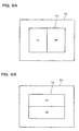
- FIG. 5A are a view illustrating the contents of coordinate data 122 before corrected.
- FIG. 5B shows the contents of coordinate data 122 after corrected.
- FIG. 6 shows the data structure of the angle correction table 124 according to one example of this embodiment.
- the coordinate table 122 has coordinates in x and y axes for deriving four corners A, B, C and D or A', B', C' and D' in the projection area 12.
- a ratio RH of average luminance values between two parts provided by horizontally dividing the projection area 12 and a ratio RV of average luminance values between two parts provided by vertically dividing the projection area 12 are respectively associated with derivation coordinates corresponding to the derivation coordinates in the coordinate table 122, as shown in FIG. 6.
- the projector 20 can uniformly determine the derivation coordinates by determining these ratios RH and RV.
- the distortion correction section 130 which functions as image signal correction means, is operative to store image signals inputted from the image signal input section 110 and corresponding to one image and to correct the image signals based on the coordinate table 122 so that any distortion in the projected image can be corrected (or resized).
- the concrete distortion correction technique may include a technique of correcting a distortion, for example, through the conventional perspective deformation.
- the image generating section 150 is operative to generate image signals used to project a calibration image such as an all-black image (a monochromatic black image) or an all-white image (a monochromatic white image, these image signals being then outputted toward the signal output section 140.
- a calibration image such as an all-black image (a monochromatic black image) or an all-white image (a monochromatic white image, these image signals being then outputted toward the signal output section 140.
- the projector 20 can solely perform the calibration without need of calibration signals inputted from any external input device such as PC or the like into the projector 20 since the calibration image signals are internally generated within the projector 20.
- the image generating section 150 may be omitted if the calibration image signals can be inputted directly into the projector from the PC or the like.
- the signal output section 140 is operative to receive the image signals corrected by the distortion correction section 130 and the calibration image signals from the image generating section 150 and to output these image signals toward the image projecting section 190 after they have been converted into analog image signals.
- the A/D conversion at the signal input section 110 and the D/A conversion at the signal output section 140 may be omitted.
- the image projecting section 190 comprises a spatial light modulator 192, a drive section 194 for driving the spatial light modulator 192, a light source 196 and a lens 198.
- the drive section 194 is operative to drive the spatial light modulator 192 based on the image signals from the signal output section 140. And, the image projecting unit 190 projects the light from the light source 196S through the spatial light modulator 192 and lens 198.
- the light source 196 may be any one of various light sources such as a point light source, surface light source and the like.
- the environment analyzing section 180 is operative to judge whether the environment is lighter or darker than a predetermined state, based on luminance information in the sensing information from the area sensor section 182.
- an average luminance value Y is determined by: 0.3 * R-signal value + 0.6 * G-signal value + 0.1 * B-signal value, it may be judged whether the environment is lighter or darker about a threshold value at which the average luminance value Y is equal about 60. This threshold is actually variable depending on the setting of the sensor 80 or the sensing region 14.
- the ambient-information analyzing section 170 updates the derivation coordinates in the coordinate table 122.
- the luminance-distribution analyzing section 160 updates the derivation coordinates in the coordinate table 122.
- Hardware structure for implementing each part of the aforementioned projector 20 may be as follows.
- FIG. 7 is a hardware block diagram illustrating a projector 20 according to one example of this embodiment.
- the signal input section 110 may be implemented by an A/D converter 930 or the like; the storage section 120 may be implemented by RAM 950 or the like; the distortion correction section 130, image generating section 150, luminance-distribution analyzing section 160, ambient-information analyzing section 170 and environment analyzing section 180 may be implemented by an image processing circuit 970, RAM 950, CPU 910 and the like, respectively; the signal output section 140 may be implemented by a D/A converter 940 or the like; and the spatial light modulator 192 may be implemented by a liquid crystal panel 920, ROM 960 for storing a liquid crystal light valve driver for driving the liquid crystal panel 920 or the like.
- These sections can be configured to mutually deliver the information therebetween through a system bus 980.
- the area sensor section 182 may be implemented by CCD sensor or the like.
- sections and portions may be implemented in a hardware manner or in a software manner such as drivers.
- the functions of the luminance-distribution analyzing section 160 and others may be implemented by a computer according to a program read out from an information storage medium 900, which program is designed to cause the computer to function as the luminance-distribution analyzing section 160 and others.
- Such an information storage medium 900 may be accomplished, for example, by CD-ROM, DVD-ROM, ROM, RAM, HDD or the like through either of the contact or non-contact type reading mode.
- the aforementioned functions can be implemented by downloading a program or the like for implementing them from a host device or the like through a transmission channel.
- FIG. 8 is a flow chart illustrating a flow of image processing according to one example of this embodiment.
- the image generating section 150 After the projector 20 has been activated, the image generating section 150 generates image signals used to project an all-black calibration image and an all-white calibration image, these image signals being then transferred to the image projecting section 190 through the signal output section 140.
- the image projecting section 190 then projects the all-black image and all-white image onto the screen 8 based on the image signals. As each of the calibration images is projected onto the screen 8, the area sensor section 182 senses the sensing region 14 including the screen region 10 and the projection area 12 (step S1).
- the area sensor section 182 then transfers the imaging information of all-black and all-white images to the environment analyzing section 180.
- the environment analyzing section 180 generates the difference information provided by subtracting the imaging information of the all-black image from the imaging information of the all-white image and detects the amount of changed luminance based on the difference information. And, the environment analyzing section 180 discriminates the projection area 12 included in the sensing region 14, based on the detected amount of changed luminance.
- the environment analyzing section 180 compares the average luminance value in the projection area 12 with a threshold to judge whether the environment is lighter or darker than a predetermined state (step S2).
- the environment analyzing section 180 judges that the average luminance value in the projection area 12 is darker than the threshold, the environment analyzing section 180 then transfers the imaging information of the all-black and all-white images and the coordinate information of the projection area 12 toward the luminance-distribution analyzing section 160.
- the luminance-distribution analyzing section 160 computes the average luminance value between the divided image parts and then the ratio of average luminance value between the respective image parts.
- FIG. 9A is a schematic diagram of an image divided into two in the vertical direction and FIG. 9B is a schematic diagram of an image divided into two in the horizontal direction.
- the projection area 12 is divided into right and left parts and that the average luminance value in the left part is YL while the average luminance value in the right part is YR, as shown in figure 9A. It is further assumed that the projection area 12 is divided into upper and lower parts and that the average luminance value in the upper part is YT while the average luminance value in the lower part is YB, as shown in figure 9B.
- the luminance-distribution analyzing section 160 determines that YR/YL is the horizontal ratio RH if YR is equal to or higher than YL; that -(YL/YR) is RH if YR is less than YL; that YT/YB is the vertical ratio RV if YT is equal to or higher than YB; and that (YB/YT) is RV if YT is less than YB.
- the luminance-distribution analyzing section 160 refers to the angle correction table 124 to acquire x and y values for four points A', B', C' and D' which respectively indicate the derivation coordinates corrected depending on the values RH and RV.
- the luminance-distribution analyzing section 160 further writes the respective acquired x and y values for the four points A', B', C' and D' into the coordinate table 122 to update it.
- the luminance-distribution analyzing section 160 detects the positional relationship between the screen 8 and projector20 based on the luminance gradient in the projection area 12 and corrects the coordinate table 122 based on the angle correction table 124 (step S3).
- the environment analyzing section 180 judges that the average luminance value in the projection area 12 is lighter than the threshold, the environment analyzing section 180 then transfers the imaging information of the all-black and all-white images and the coordinate information of the projection area 12 toward the ambient-information analyzing section 170.
- the ambient-information analyzing section 170 detects the coordinate information in the screen region 10 based on the luminance distribution from the imaging information of the all-black image.
- the ambient-information analyzing section 170 corrects the coordinate table 122 using the coordinates for four corners in the screen region 10 and based on the coordinate information of the projection area 12 and the coordinate information of the screen region 10.
- the ambient-information analyzing section 170 sets a rectangle consisted of four corner coordinates in the screen region 10 and reduces and translates the rectangle such that the rectangle is completely included in the interior of the projection area 12, as shown in FIG. 11.
- the ambient-information analyzing section 170 then corrects the coordinate table 122 using the four corner coordinates at a point of time when the rectangle is completely included in the projection area 12.
- the portion of the projection area 12 which has been hidden through these procedures may display an image having a color (e.g., black) identical with that of the screen region 10.
- the ambient-information analyzing section 170 corrects the coordinate table 122 to match the configuration of the projection area 12 to the screen region 10 (step S4).
- the distortion correction section 130 then corrects the image signals to correct the distortion of the image based on the four-comer coordinate deriving information included in the coordinate table 122 which has been corrected by the luminance-distribution analyzing section 160 or ambient-information analyzing section 170 (step S5).
- the image projecting section 190 then projects an image based on the corrected image signals (step S6).
- the projector 20 projects the image in which any keystone distortion has been corrected.
- FIG. 10 is diagrammatic view showing an image after its keystone distortion has been corrected according to one example of this embodiment.
- the projection area 12 may be in the form of such a trapezoid as shown by a tetragon ABCD.
- the projector 20 can form a projection area 13 into such a rectangular shape as shown by A'B'C'D', by correcting the image signals.
- the projector 20 can determine a distortion in the projection area 12 based on the distribution of luminance value.
- the projector 20 can adequately discriminate the image distortion even in such a case that it is difficult to discriminate the distortion from the shape of the sensed image since the optical axes of the lens 198 and sensor 30 are identical with each other.
- the distortion in the projected image can be corrected automatically and adequately.
- a sensor having its lower resolution can be applied as the sensor 30 since it is not necessary to exactly determine the shape of the projection area 12 and since only the luminance distribution in the projection area 12 is required.
- the image distortion can adequately be corrected by discriminating whether the environment is lighter or darker. If it is difficult to discriminate any change in the luminance value, such correction can be accomplished by updating four derivation coordinates in the coordinate data 122 using the positional information relating to the respective vertexes on the screen region 10.
- the projector 20 can be applied in various kinds of operating environments.
- the projector 20 can correct the image even if the distortion on the projection area 12 is due to rotation.
- FIG. 12 is diagrammatic view illustrating a corrected image which had been rotated according to one example of this embodiment.
- the ambient-information analyzing section 170 sets a rectangle comprising coordinates for four corners on the screen region 10, and reduces and translates the rectangle so that it is completely included in the interior of the projection area 12. The ambient-information analyzing section 170 then corrects the coordinate table 122 using the four corner coordinates at a point of time when the rectangle is completely included in the projection area 12.
- an inclination or gravity sensor may be mounted in the projector 20 such that the vertical distortion in a trapezoid can be corrected by such a sensor while the horizontal distortion in the trapezoid can be corrected based on the sensing information from the sensor 30.
- the projector 20 may acquire information relating to the zooming (e.g., numerical values as represented by zero at the maximum telescopic sight and by one at the maximum pantoscopic sight) and then correct the keystone distortion based on this information.
- information relating to the zooming e.g., numerical values as represented by zero at the maximum telescopic sight and by one at the maximum pantoscopic sight
- the keystone distortion can be corrected automatically and adequately even if the telescopic or pantoscopic function is to be used.
- the projection area 12 may be divided into plural regions other than two (e.g., four, nine or others).
- the projector 20 may determine the average luminance value for each of the divided regions for image processing.
- the ratio of average luminance value may be replaced by a differential value in the average luminance value.
- the present invention is not limited to such calibration images and can be applied to any of various kinds of calibration images.
- the present invention is effectively applied to any one of various front-projection type image display devices other than the projector 20.
- the projector 20 may be a liquid crystal projector or a projector using DMD (Digital Micromirror Device).
- DMD Digital Micromirror Device
- DMD is a trademark possessed by the U. S. Texas Instruments.
- the function of the projector 20 may be accomplished solely by the projector 20 or by a plurality of decentralized processing units (e.g., one projector and one PC).
- the projector 20 may be separated from the sensor 30 or they may be formed as one unit.
Landscapes
- Engineering & Computer Science (AREA)
- Multimedia (AREA)
- Signal Processing (AREA)
- Aviation & Aerospace Engineering (AREA)
- Transportation (AREA)
- Mechanical Engineering (AREA)
- Health & Medical Sciences (AREA)
- Geometry (AREA)
- Physics & Mathematics (AREA)
- Child & Adolescent Psychology (AREA)
- General Health & Medical Sciences (AREA)
- Projection Apparatus (AREA)
- Transforming Electric Information Into Light Information (AREA)
- Controls And Circuits For Display Device (AREA)
- Liquid Crystal Display Device Control (AREA)
- Control Of Indicators Other Than Cathode Ray Tubes (AREA)
Applications Claiming Priority (2)
| Application Number | Priority Date | Filing Date | Title |
|---|---|---|---|
| JP2003009690 | 2003-01-17 | ||
| JP2003009690A JP3844075B2 (ja) | 2003-01-17 | 2003-01-17 | 画像処理システム、プロジェクタ、プログラム、情報記憶媒体および画像処理方法 |
Publications (2)
| Publication Number | Publication Date |
|---|---|
| EP1439694A1 EP1439694A1 (en) | 2004-07-21 |
| EP1439694B1 true EP1439694B1 (en) | 2007-09-19 |
Family
ID=32588564
Family Applications (1)
| Application Number | Title | Priority Date | Filing Date |
|---|---|---|---|
| EP04250226A Expired - Fee Related EP1439694B1 (en) | 2003-01-17 | 2004-01-16 | Image processing system, projector and image processing method |
Country Status (7)
| Country | Link |
|---|---|
| US (1) | US6932479B2 (ko) |
| EP (1) | EP1439694B1 (ko) |
| JP (1) | JP3844075B2 (ko) |
| KR (1) | KR100593113B1 (ko) |
| CN (2) | CN2686241Y (ko) |
| DE (1) | DE602004008975T2 (ko) |
| TW (1) | TWI235944B (ko) |
Families Citing this family (37)
| Publication number | Priority date | Publication date | Assignee | Title |
|---|---|---|---|---|
| JP4150924B2 (ja) * | 2003-07-02 | 2008-09-17 | セイコーエプソン株式会社 | 画像処理システム、プロジェクタ、プログラム、情報記憶媒体および画像処理方法 |
| JP4260634B2 (ja) * | 2002-02-15 | 2009-04-30 | 富士通株式会社 | 画像変換方法及び装置、画像認識装置、ロボット制御装置並びに画像投影装置 |
| JP3541845B1 (ja) * | 2003-02-17 | 2004-07-14 | セイコーエプソン株式会社 | プロジェクタの画像補正方法及びプロジェクタ |
| JP3871061B2 (ja) | 2003-03-25 | 2007-01-24 | セイコーエプソン株式会社 | 画像処理システム、プロジェクタ、プログラム、情報記憶媒体および画像処理方法 |
| JP3846592B2 (ja) * | 2003-06-26 | 2006-11-15 | セイコーエプソン株式会社 | 画像処理システム、プロジェクタ、プログラム、情報記憶媒体および画像処理方法 |
| JP4055010B2 (ja) * | 2003-09-26 | 2008-03-05 | セイコーエプソン株式会社 | 画像処理システム、プロジェクタ、プログラム、情報記憶媒体および画像処理方法 |
| DE10347388A1 (de) * | 2003-10-08 | 2005-05-04 | Zeiss Carl Jena Gmbh | Anordnung zur Korrektur der visuellen Darstellung von Bildinformationen |
| WO2006008791A1 (ja) * | 2004-07-15 | 2006-01-26 | Sharp Kabushiki Kaisha | 画像投射方法、プロジェクタ、及びコンピュータプログラム |
| WO2006008792A1 (ja) * | 2004-07-15 | 2006-01-26 | Sharp Kabushiki Kaisha | 画像投射方法、プロジェクタ、及びコンピュータプログラム |
| ATE488091T1 (de) * | 2004-08-30 | 2010-11-15 | Univ Weimar Bauhaus | Verfahren und vorrichtung zur darstellung eines digitalen bildes auf einer geometrisch und photometrisch nicht-trivialen oberfläche |
| JP4196951B2 (ja) * | 2005-02-04 | 2008-12-17 | セイコーエプソン株式会社 | プロジェクタ、投写画像調整方法 |
| DE102005034990B4 (de) * | 2005-03-21 | 2008-11-20 | Bauhaus Universität Weimar | Verfahren und Vorrichtung zur Digitalprojektion mit hoher Bildschärfe |
| US8089567B2 (en) | 2005-07-29 | 2012-01-03 | Optoma Technology, Inc. | Methods and systems for displaying video on an adjustable screen |
| US7701518B2 (en) * | 2005-07-29 | 2010-04-20 | Optoma Technology, Inc. | Methods and systems for displaying video in multiple aspect ratios |
| US20070024764A1 (en) * | 2005-07-29 | 2007-02-01 | Optoma Technology, Inc. | Methods and systems that compensate for distortion introduced by anamorphic lenses in a video projector |
| US20070024823A1 (en) * | 2005-07-29 | 2007-02-01 | Optoma Technology, Inc. | Methods and systems for improving operation of a video projector |
| US7357514B2 (en) * | 2005-07-29 | 2008-04-15 | Optoma Technology, Inc. | Methods and systems for improving operation of a video projector |
| US20070025273A1 (en) * | 2005-07-29 | 2007-02-01 | Chung Yau W | Methods and systems for detecting video signals and sources |
| US7434937B2 (en) | 2005-07-29 | 2008-10-14 | Optoma Technology, Inc. | Methods and systems for calibrating rear projection video |
| US7787062B2 (en) * | 2006-05-19 | 2010-08-31 | Chunghwa Picture Tubes, Ltd. | Rear projection display and circuit and method for adjusting image thereof |
| CN100531318C (zh) * | 2006-10-09 | 2009-08-19 | 亚洲光学股份有限公司 | 可稳定摄像的摄像系统及方法 |
| EP2449787A1 (en) * | 2009-07-02 | 2012-05-09 | Thomson Licensing | Method and system for differential distortion correction for three-dimensional (3d) projection |
| WO2011014692A1 (en) * | 2009-07-29 | 2011-02-03 | Thomson Licensing | Method for crosstalk correction for three-dimensional (3d) projection |
| EP2465269A1 (en) * | 2009-08-12 | 2012-06-20 | Thomson Licensing | Method and system for crosstalk and distortion corrections for three-dimensional (3d) projection |
| JP5444947B2 (ja) * | 2009-08-26 | 2014-03-19 | 株式会社ニコン | プロジェクタ |
| DE102009046114B4 (de) * | 2009-10-28 | 2011-09-01 | Fraunhofer-Gesellschaft zur Förderung der angewandten Forschung e.V. | Verfahren und Vorrichtung zum Erzeugen einer kalibrierten Projektion |
| CN103020950B (zh) * | 2011-09-27 | 2015-09-09 | 华为终端有限公司 | 亮度函数获取方法以及相关装置 |
| JP6089424B2 (ja) * | 2012-03-21 | 2017-03-08 | セイコーエプソン株式会社 | 画像処理装置、プロジェクター、およびプロジェクターの制御方法 |
| JP5842694B2 (ja) | 2012-03-21 | 2016-01-13 | セイコーエプソン株式会社 | 画像処理装置、プロジェクター、およびプロジェクターの制御方法 |
| US9626748B2 (en) * | 2012-07-02 | 2017-04-18 | Seiko Epson Corporation | Projector and method for controlling the same |
| CN103096007B (zh) * | 2013-01-07 | 2015-10-21 | 苏州佳世达光电有限公司 | 互动式投影系统及其校正方法 |
| JP6056692B2 (ja) * | 2013-07-16 | 2017-01-11 | 株式会社デンソー | 検査装置 |
| CN105357447B (zh) * | 2015-10-30 | 2020-03-13 | 努比亚技术有限公司 | 图片处理方法及装置 |
| CN107422590B (zh) * | 2017-09-12 | 2020-09-08 | 中广热点云科技有限公司 | 自动调节投影面大小的家用投影系统 |
| CN109040725B (zh) * | 2018-08-31 | 2020-04-14 | 成都极米科技股份有限公司 | 基于投影装置使用环境的投影角度调整方法及投影装置 |
| DE102019100480A1 (de) | 2019-01-10 | 2020-07-16 | Carl Zeiss Jena Gmbh | Projektor zum Projizieren von Bildern |
| KR102105801B1 (ko) * | 2019-11-13 | 2020-04-29 | 주식회사 애즈원 | 기울기를 갖는 led 전광판에 영상을 표현하기 위한 led 전광판 시스템 |
Family Cites Families (14)
| Publication number | Priority date | Publication date | Assignee | Title |
|---|---|---|---|---|
| JP2653899B2 (ja) * | 1990-06-07 | 1997-09-17 | 松下電器産業株式会社 | 画像補正装置 |
| JP2861333B2 (ja) * | 1990-08-29 | 1999-02-24 | 松下電器産業株式会社 | 画像補正装置 |
| WO1992015084A1 (en) * | 1991-02-14 | 1992-09-03 | Proxima Corporation | Method and apparatus for calibrating geometrically an optical computer input system |
| JP2709423B2 (ja) * | 1991-11-13 | 1998-02-04 | 株式会社エイ・ティ・アール通信システム研究所 | 表示装置 |
| DE69422074D1 (de) * | 1993-03-17 | 2000-01-20 | Matsushita Electric Ind Co Ltd | Bildkorrekturvorrichtung |
| JPH07131672A (ja) * | 1993-10-28 | 1995-05-19 | Mitsubishi Electric Corp | ワイドアスペクトテレビジョン受像機 |
| JP3688399B2 (ja) * | 1996-07-26 | 2005-08-24 | 株式会社東芝 | 歪補正回路 |
| JP2002527953A (ja) * | 1998-10-02 | 2002-08-27 | マクロニクス インターナショナル カンパニー リミテッド | キーストーン歪みを防止する方法および装置 |
| JP2000241874A (ja) | 1999-02-19 | 2000-09-08 | Nec Corp | プロジェクタの自動画面位置調整方法及び装置 |
| EP1164784A1 (en) * | 2000-06-13 | 2001-12-19 | Koninklijke Philips Electronics N.V. | Preventing doming phenomena |
| JP2002044571A (ja) | 2000-07-27 | 2002-02-08 | Nec Viewtechnology Ltd | 投射型の格子状表示装置及び投射映像の歪み補正方法 |
| JP2002247614A (ja) | 2001-02-15 | 2002-08-30 | Ricoh Co Ltd | プロゼェクタ |
| AU2002312676A1 (en) | 2001-06-12 | 2002-12-23 | Silicon Optix Inc. | System and method for correcting keystone distortion |
| KR100429874B1 (ko) * | 2001-07-20 | 2004-05-04 | 삼성전자주식회사 | 파노라마/워터글라스 기능 구현을 위한 영상 처리 장치 및그 방법 |
-
2003
- 2003-01-17 JP JP2003009690A patent/JP3844075B2/ja not_active Expired - Fee Related
-
2004
- 2004-01-15 US US10/757,442 patent/US6932479B2/en not_active Expired - Fee Related
- 2004-01-16 CN CNU2004200011614U patent/CN2686241Y/zh not_active Expired - Fee Related
- 2004-01-16 CN CNB2004100010527A patent/CN100459676C/zh not_active Expired - Fee Related
- 2004-01-16 EP EP04250226A patent/EP1439694B1/en not_active Expired - Fee Related
- 2004-01-16 KR KR1020040003185A patent/KR100593113B1/ko not_active IP Right Cessation
- 2004-01-16 DE DE602004008975T patent/DE602004008975T2/de not_active Expired - Lifetime
- 2004-01-16 TW TW093101238A patent/TWI235944B/zh not_active IP Right Cessation
Also Published As
| Publication number | Publication date |
|---|---|
| TW200424917A (en) | 2004-11-16 |
| DE602004008975T2 (de) | 2008-06-19 |
| US6932479B2 (en) | 2005-08-23 |
| JP2004222153A (ja) | 2004-08-05 |
| EP1439694A1 (en) | 2004-07-21 |
| TWI235944B (en) | 2005-07-11 |
| JP3844075B2 (ja) | 2006-11-08 |
| KR20040067924A (ko) | 2004-07-30 |
| US20040201825A1 (en) | 2004-10-14 |
| DE602004008975D1 (de) | 2007-10-31 |
| CN100459676C (zh) | 2009-02-04 |
| CN1517784A (zh) | 2004-08-04 |
| CN2686241Y (zh) | 2005-03-16 |
| KR100593113B1 (ko) | 2006-06-26 |
Similar Documents
| Publication | Publication Date | Title |
|---|---|---|
| EP1439694B1 (en) | Image processing system, projector and image processing method | |
| EP1492355B1 (en) | Image processing system, projector, information storage medium and image processing method | |
| EP1473933B1 (en) | Image processing system, projector, information storage medium and image processing method | |
| US7949202B2 (en) | Image processing system, projector, and image processing method | |
| US7422331B2 (en) | Image processing system, projector, and image processing method | |
| EP1455528B1 (en) | Image processing system and image processing method | |
| EP1463338B1 (en) | System, method and software for processing a projected image | |
| EP1519576B1 (en) | Image processing system, projector, information storage medium, and image processing method | |
| JP4340923B2 (ja) | プロジェクタ、プログラムおよび情報記憶媒体 | |
| TWI266224B (en) | Image processing system, projector, information memory media and image processing method | |
| KR20040048850A (ko) | 화상 처리 시스템, 프로젝터, 휴대형 장치 및 화상 처리방법 | |
| JP2004029110A (ja) | 投射型表示装置 | |
| JP3882927B2 (ja) | 画像処理システム、プロジェクタおよび画像処理方法 | |
| US20230028087A1 (en) | Control apparatus, image projection system, control method, and storage medium | |
| JP4511433B2 (ja) | 画像処理システム、プロジェクタ、携帯型装置および画像処理方法 |
Legal Events
| Date | Code | Title | Description |
|---|---|---|---|
| PUAI | Public reference made under article 153(3) epc to a published international application that has entered the european phase |
Free format text: ORIGINAL CODE: 0009012 |
|
| AK | Designated contracting states |
Kind code of ref document: A1 Designated state(s): AT BE BG CH CY CZ DE DK EE ES FI FR GB GR HU IE IT LI LU MC NL PT RO SE SI SK TR |
|
| AX | Request for extension of the european patent |
Extension state: AL LT LV MK |
|
| 17P | Request for examination filed |
Effective date: 20041222 |
|
| 17Q | First examination report despatched |
Effective date: 20050117 |
|
| AKX | Designation fees paid |
Designated state(s): DE FR GB |
|
| 17Q | First examination report despatched |
Effective date: 20050117 |
|
| GRAP | Despatch of communication of intention to grant a patent |
Free format text: ORIGINAL CODE: EPIDOSNIGR1 |
|
| GRAS | Grant fee paid |
Free format text: ORIGINAL CODE: EPIDOSNIGR3 |
|
| GRAA | (expected) grant |
Free format text: ORIGINAL CODE: 0009210 |
|
| AK | Designated contracting states |
Kind code of ref document: B1 Designated state(s): DE FR GB |
|
| REG | Reference to a national code |
Ref country code: GB Ref legal event code: FG4D |
|
| REF | Corresponds to: |
Ref document number: 602004008975 Country of ref document: DE Date of ref document: 20071031 Kind code of ref document: P |
|
| ET | Fr: translation filed | ||
| PLBE | No opposition filed within time limit |
Free format text: ORIGINAL CODE: 0009261 |
|
| STAA | Information on the status of an ep patent application or granted ep patent |
Free format text: STATUS: NO OPPOSITION FILED WITHIN TIME LIMIT |
|
| 26N | No opposition filed |
Effective date: 20080620 |
|
| REG | Reference to a national code |
Ref country code: FR Ref legal event code: PLFP Year of fee payment: 13 |
|
| PGFP | Annual fee paid to national office [announced via postgrant information from national office to epo] |
Ref country code: FR Payment date: 20151208 Year of fee payment: 13 |
|
| PGFP | Annual fee paid to national office [announced via postgrant information from national office to epo] |
Ref country code: DE Payment date: 20160112 Year of fee payment: 13 |
|
| PGFP | Annual fee paid to national office [announced via postgrant information from national office to epo] |
Ref country code: GB Payment date: 20160113 Year of fee payment: 13 |
|
| REG | Reference to a national code |
Ref country code: DE Ref legal event code: R119 Ref document number: 602004008975 Country of ref document: DE |
|
| GBPC | Gb: european patent ceased through non-payment of renewal fee |
Effective date: 20170116 |
|
| REG | Reference to a national code |
Ref country code: FR Ref legal event code: ST Effective date: 20170929 |
|
| PG25 | Lapsed in a contracting state [announced via postgrant information from national office to epo] |
Ref country code: FR Free format text: LAPSE BECAUSE OF NON-PAYMENT OF DUE FEES Effective date: 20170131 |
|
| PG25 | Lapsed in a contracting state [announced via postgrant information from national office to epo] |
Ref country code: DE Free format text: LAPSE BECAUSE OF NON-PAYMENT OF DUE FEES Effective date: 20170801 Ref country code: GB Free format text: LAPSE BECAUSE OF NON-PAYMENT OF DUE FEES Effective date: 20170116 |