EP1437461A2 - Verfahren zur Herstellung einer Türschlossvorrichtung für ein Kraftfahrzeug sowie eine durch ein derartiges Verfahren hergestellte Türschlossvorrichtung - Google Patents
Verfahren zur Herstellung einer Türschlossvorrichtung für ein Kraftfahrzeug sowie eine durch ein derartiges Verfahren hergestellte Türschlossvorrichtung Download PDFInfo
- Publication number
- EP1437461A2 EP1437461A2 EP03029158A EP03029158A EP1437461A2 EP 1437461 A2 EP1437461 A2 EP 1437461A2 EP 03029158 A EP03029158 A EP 03029158A EP 03029158 A EP03029158 A EP 03029158A EP 1437461 A2 EP1437461 A2 EP 1437461A2
- Authority
- EP
- European Patent Office
- Prior art keywords
- vehicle
- partner
- door lock
- lock device
- handle
- Prior art date
- Legal status (The legal status is an assumption and is not a legal conclusion. Google has not performed a legal analysis and makes no representation as to the accuracy of the status listed.)
- Granted
Links
Images




Classifications
-
- E—FIXED CONSTRUCTIONS
- E05—LOCKS; KEYS; WINDOW OR DOOR FITTINGS; SAFES
- E05B—LOCKS; ACCESSORIES THEREFOR; HANDCUFFS
- E05B85/00—Details of vehicle locks not provided for in groups E05B77/00 - E05B83/00
- E05B85/10—Handles
- E05B85/14—Handles pivoted about an axis parallel to the wing
- E05B85/16—Handles pivoted about an axis parallel to the wing a longitudinal grip part being pivoted at one end about an axis perpendicular to the longitudinal axis of the grip part
-
- E—FIXED CONSTRUCTIONS
- E05—LOCKS; KEYS; WINDOW OR DOOR FITTINGS; SAFES
- E05B—LOCKS; ACCESSORIES THEREFOR; HANDCUFFS
- E05B79/00—Mounting or connecting vehicle locks or parts thereof
- E05B79/02—Mounting of vehicle locks or parts thereof
- E05B79/06—Mounting of handles, e.g. to the wing or to the lock
-
- E—FIXED CONSTRUCTIONS
- E05—LOCKS; KEYS; WINDOW OR DOOR FITTINGS; SAFES
- E05B—LOCKS; ACCESSORIES THEREFOR; HANDCUFFS
- E05B81/00—Power-actuated vehicle locks
- E05B81/54—Electrical circuits
- E05B81/64—Monitoring or sensing, e.g. by using switches or sensors
- E05B81/76—Detection of handle operation; Detection of a user approaching a handle; Electrical switching actions performed by door handles
- E05B81/78—Detection of handle operation; Detection of a user approaching a handle; Electrical switching actions performed by door handles as part of a hands-free locking or unlocking operation
Definitions
- the present invention relates to a method for Production of a door lock device for a motor vehicle comprising an actuatable handle unit, the at least one electronic component and a handle side connector for having the electrical connection with the motor vehicle, and furthermore comprising a vehicle-mounted storage unit, which can accommodate the handle unit pivotally and a vehicle-side connector for the electrical connection having the handle side connector, wherein in one first step of the vehicle-side partners the vehicle-side storage unit in a mounting position is attached, in a second step of the handle side connector with the vehicle side connector is connected and in a third step of the vehicle-side connector along with the griff workedem Connector from the mounting position to an operating position the door lock device is transferred. Furthermore the present invention by such a method manufactured door lock device.
- a method and a door lock device of the aforementioned Kind are from the European patent application EP 1 255 004 A2 known.
- the handle unit of such Door lock device can be used as electronic components
- sensor means or transmitting and receiving means include the term known as "keyless entry" to allow electronic opening of the vehicle door.
- the sensor means may be Proximity switches act that approach the hand's hand User can detect.
- the problem underlying the present invention is the statement of a method of the type mentioned, with the the production of a door lock device of the beginning mentioned type is easier to carry out. Furthermore, a should Door lock device to be created with this Method can be produced.
- the outward movement of on-board mating partner from the month position position during of the third process step by a pivoting movement he follows.
- a pivoting movement is easier during assembly feasible.
- parts of the Handle unit such as a handle or the like are used as levers, so when the Swivel movement easily forces larger forces on the vehicle-side connector can be exercised, the so problem-free from a possible catch with the Storage unit can be solved.
- the pivoting movement takes place about a pivot axis, which is parallel to a pivot axis around which the Handle unit for opening the door lock device opposite the vehicle-side storage unit is pivotable.
- the Pivoting movement for mounting the door lock device can thus partially resembling the pivoting movement that the Handle unit relative to the storage unit in the operating position to perform the unlocking of the door lock device.
- the transfer of the vehicle side mating partner from the assembly position into the Operating position one, preferably rectilinear, Moving movement includes.
- the Moving movement the transfer of the vehicle side Plug-in partner from the mounting position to the operating position to lock.
- the door lock device comprises a cable having a Connection between the vehicle-side partner and the On-board electronics of the motor vehicle manufactures, wherein the cable during the transfer of the vehicle-side mating partner the mounting position is clamped in the operating position.
- a door lock device is characterized characterized in that they are obtained by a method according to any one of Claims 1 to 5 is produced.
- a Door lock device can be provided that the Vehicle-side connector in the mounting position with the Bearing unit is locked. Due to the invention Swinging motion calls such a locking connection between vehicle side connector and storage unit no problems during assembly.
- the storage unit comprises one towards the handle unit opened recess in which the vehicle-side connector is arranged.
- the Handle unit comprises a bearing lug on which the handle side Plug-in partner is arranged, wherein during the Pivoting movement of handle unit to bearing unit of Bearing unit facing side of the bearing projection convex and / or rounded is formed to the pivoting movement support.
- an inventive device comprises Door lock device a handle unit 1 and a Vehicle-side storage unit 2.
- the handle unit 1 and the Bearing unit 2 can by the method according to the invention be connected together in such a way that they are in one Operating position, most clearly from Fig. 2d is apparent. In this operating position, the Handle unit 1 slightly opposite the storage unit 2 for pivoted mechanical unlocking the door lock device become.
- the handle unit 1 comprises at least one inside electronic component.
- This electronic component can For example, comprise a sensor electronics and an antenna. With the sensor electronics, the approach of a human Hand detected. About the antenna or over a Transmitter and receiver unit may be with a Electronic key to be communicated to the user of the vehicle can carry.
- the handle unit 1 comprises the actual handle bar 3, to the user for mechanical unlocking the Door lock device can attack, as well as at the End subsequent approaches, namely a bearing approach 4 and a Entriegelungsansatz 5.
- the Entriegelungsansatz 5 can known in the art in a corresponding manner Recess 6 of the vehicle-side storage unit 2 engage and upon actuation of the handle 3 by the user a cause mechanical unlocking of the door lock device.
- the handle unit 1 further comprises on the handle of the handle 3 opposite end of the bearing lug 4 a handle side Connector 7, with a vehicle-side connector 8 can be connected in an assembly position in one Recess 9 of the storage unit 2 is arranged.
- a handle side Connector 7 By the Connection of the two connectors 7, 8 is an electrical Connection between the at least one electronic component in the handle unit 1 and the on-board electronics of the motor vehicle produced.
- the connection between the vehicle side Connector 8 and the on-board electronics takes place via a For example, from Fig. 2a to Fig. 2d apparent cable 10th
- the storage unit 2 comprises between the two aforementioned Recesses 6, 9 a recessed grip 11, the Schugreifung the handle bar 3 in the operating position of the invention Door lock device is used.
- the off Fig. 1, Fig. 2a, Fig. 3a and Fig. 4a is visible, is the vehicle-side connector 8 with a holding part 12 of Bearing unit 2 locked, the vehicle inside of the Gripping recess 11 extends under the recess 9.
- This to Locking serving holding part 12 in this case has an end Rejuvenation on, whose tip is in a in the same direction tapered recess 13 in the vehicle-side connector 8 can intervene.
- This arrangement prevents at the Connection of handle side connector 7 and vehicle-side connector 8 of the vehicle side Connector 8 in the connection direction according to the arrow 14 in Fig. 2a in the interior of the motor vehicle, in particular in the Door cavity is pushed into it.
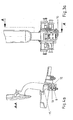
- Fig. 1 Fig. 1
- Fig. 2a FIGS. 3 a and 4 a show the handle unit 1 and the bearing unit 2 before making this connection.
- Fig. 2a further shows by means of the arrow 14, in which direction the bearing approach 4 The handle unit 1 must be moved to the connection manufacture.
- Fig. 2b, 3b and Fig. 4b show the Door lock device according to the invention after manufactured electrical and mechanical connection between handle side Plug-in partner 7 and vehicle-side partner 8.
- FIG. 2c Following the connection of the plug-in partners 7, 8 with each other is shown in FIG. 2c, Fig. 3c and Fig. 4c on the handle bar. 3 exerted a force, so that a pivoting movement of the Handle unit 1 relative to the storage unit 2 takes place.
- the Pivoting movement takes place in the direction of arrow 16 in Fig. 4c.
- the bearing lug 4 of the handle unit 1 is during the Pivoting movement is performed at three points of the storage unit 2, namely, on the one hand at the top of the holding part 12 and the others at the two upper lateral boundaries 17, 18 of the Recess 9 (see Fig. 4c).
- Fig. 4c In particular, in Fig.
- Operating position of the door lock device is the cable 10, at the beginning of the connection of handle unit 1 and Storage unit 2 loose in loops, cocked.
- the Operating position is after completion of the swing of the Handle unit 1 relative to the storage unit 2 by a preferably straight-line displacement movement in the direction of Arrow 20 in Fig. 4d of handle unit 1 opposite storage unit 2 reached.
Landscapes
- Lock And Its Accessories (AREA)
Abstract
Description
- Fig. 1
- eine perspektivische Ansicht einer erfindungsgemäßen Türschlossvorrichtung, bei der Griffeinheit und Lagereinheit nicht miteinander verbunden sind;
- Fig. 2a
- eine teilweise geschnittene perspektivische Ansicht der Türschlossvorrichtung, gemäß Fig. 1 in nicht miteinander verbundenem Zustand von Griffeinheit und Lagereinheit;
- Fig. 2b
- eine Fig. 2a entsprechende Ansicht nach erfolgtem miteinander Verbinden der Steckpartner;
- Fig. 2c
- eine Fig. 2a entsprechende Ansicht der Türschlossvorrichtung während der Verschwenkung von Griffeinheit zu Lagereinheit;
- Fig. 2d
- eine Fig. 2a entsprechende Ansicht mit in Betriebsposition,befindlicher Griffeinheit;
- Fig. 3a
- eine teilweise geschnittene Vorderansicht der Türschlossvorrichtung in dem Zustand gemäß Fig. 2a;
- Fig. 3b
- eine Fig. 3a entsprechende Ansicht auf die Türschlossvorrichtung in dem Zustand gemäß Fig. 2b;
- Fig. 3c
- eine Fig. 3a entsprechende Ansicht auf die Türschlossvorrichtung in dem Zustand gemäß Fig. 2c;
- Fig. 3d
- eine Fig. 3a entsprechende Ansicht auf die Türschlossvorrichtung in dem Zustand gemäß Fig. 2d;
- Fig. 4a
- eine Ansicht gemäß den Pfeilen A-A in Fig. 3a;
- Fig. 4b
- eine Ansicht gemäß den Pfeilen B-B in Fig. 3b;
- Fig. 4c
- eine Ansicht gemäß den Pfeilen C-C in Fig. 3c;
- Fig. 4d
- eine Ansicht gemäß den Pfeilen D-D in Fig. 3d;
- Fig. 5
- eine perspektivische Detailansicht der miteinander verbundenen Steckpartner.
- 1
- Griffeinheit
- 2
- Lagereinheit
- 3
- Griffbügel
- 4
- Lageransatz
- 5
- Entriegelungsansatz
- 6
- Ausnehmung für 5
- 7
- Griffseitiger Steckpartner
- 8
- Fahrzeugseitiger Steckpartner
- 9
- Ausnehmung für 8
- 10
- Kabel
- 11
- Griffmulde
- 12
- Halteteil
- 13
- Ausnehmung für 12
- 14
- Pfeil
- 15
- Rastelement
- 16
- Pfeil
- 17, 18
- Seitliche Begrenzungen von 9
- 19
- Unterseite von 4
- 20
- Pfeil
Claims (10)
- Verfahren zur Herstellung einer Türschlossvorrichtung für ein Kraftfahrzeug umfassend eine betätigbare Griffeinheit (1), die zumindest ein elektronisches Bauteil und einen griffseitigen Steckpartner (7) für die elektrische Verbindung mit dem Kraftfahrzeug aufweist, sowie weiterhin umfassend eine fahrzeugseitige Lagereinheit (2), die die Griffeinheit (1) schwenkbar aufnehmen kann und einen fahrzeugseitigen Steckpartner (8) für die elektrische Verbindung mit dem griffseitigen Steckpartner (7) aufweist, wobeidadurch gekennzeichnet, dass die Herausbewegung des fahrzeugseitigen Steckpartners (8) aus der Montageposition während des dritten Verfahrensschrittes durch eine Schwenkbewegung erfolgt.in einem ersten Verfahrensschritt der fahrzeugseitige Steckpartner (7) an der fahrzeugseitigen Lagereinheit (2) in einer Montageposition angebracht wird;in einem zweiten Verfahrensschritt der griffseitige Steckpartner (7) mit dem fahrzeugseitigem Steckpartner (8) verbunden wird undin einem dritten Verfahrensschritt der fahrzeugseitige Steckpartner (8) zusammen mit dem griffseitigem Steckpartner (7) aus der Montageposition in eine Betriebsposition der Türschlossvorrichtung überführt wird;
- Verfahren nach Anspruch 1, dadurch gekennzeichnet, dass die Schwenkbewegung um eine Schwenkachse erfolgt, die parallel zu einer Schwenkachse ist, um die herum die Griffeinheit (1) zur Öffnung der Türschlossvorrichtung gegenüber der fahrzeugseitigen Lagereinheit (2) verschwenkbar ist.
- Verfahren nach einem der Ansprüche 1 oder 2, dadurch gekennzeichnet, dass die Überführung des fahrzeugseitigem Steckpartners (8) aus der Montageposition in die Betriebsposition eine, vorzugsweise gradlinige, Verschiebebewegung umfasst.
- Verfahren nach Anspruch 3, dadurch gekennzeichnet, dass die Verschiebebewegung die Überführung des fahrzeugseitigem Steckpartners (8) aus der Montageposition in die Betriebsposition abschließt.
- Verfahren nach einem der Ansprüche 1 bis 4, dadurch gekennzeichnet, dass die Türschlossvorrichtung ein Kabel (10) umfasst, das eine Verbindung zwischen dem fahrzeugseitigen Steckpartner (8) und der Bordelektronik des Kraftfahrzeugs herstellt, wobei das Kabel (10) während der Überführung des fahrzeugseitigen Steckpartners (8) aus der Montageposition in die Betriebsposition gespannt wird.
- Türschlossvorrichtung für ein Kraftfahrzeug mit den Merkmalen des Oberbegriffs des Anspruchs 1, gekennzeichnet durch die Herstellung durch ein Verfahren nach einem der Ansprüche 1 bis 5.
- Türschlossvorrichtung nach Anspruch 6, dadurch gekennzeichnet, dass der fahrzeugseitige Steckpartner (8) in der Montageposition mit der Lagereinheit (2) verrastet ist.
- Türschlossvorrichtung nach einem der Ansprüche 6 oder 7, dadurch gekennzeichnet, dass die Lagereinheit (2) eine zur Griffeinheit (1) hin geöffnete Ausnehmung (9) umfasst, in der der fahrzeugseitige Steckpartner (8) angeordnet ist.
- Türschlossvorrichtung nach Anspruch 8, dadurch gekennzeichnet, dass endseitige seitliche Begrenzungen (17, 18) der Ausnehmung (9) zumindest abschnittsweise trichterförmig ausgebildet sind, um das Verschwenken von griffeinheit (1) zu Lagereinheit (2) zu unterstützen.
- Türschlossvorrichtung nach einem der Ansprüche 6 oder 9, dadurch gekennzeichnet, dass die Griffeinheit (1) einen Lageransatz (4) umfasst, an dem der griffseitige Steckpartner (7) angeordnet ist, wobei die während der Schwenkbewegung von Griffeinheit (1) zu Lagereinheit (2) der Lagereinheit (2) zugewandte Seite des Lageransatzes (4) konvex und/oder abgerundet ausgebildet ist, um die Schwenkbewegung zu unterstützen.
Applications Claiming Priority (2)
| Application Number | Priority Date | Filing Date | Title |
|---|---|---|---|
| DE2003100766 DE10300766A1 (de) | 2003-01-11 | 2003-01-11 | Verfahren zur Herstellung einer Türschlossvorrichtung für ein Kraftfahrzeug sowie eine durch ein derartiges Verfahren hergestellte Türschlossvorrichtung |
| DE10300766 | 2003-01-11 |
Publications (3)
| Publication Number | Publication Date |
|---|---|
| EP1437461A2 true EP1437461A2 (de) | 2004-07-14 |
| EP1437461A3 EP1437461A3 (de) | 2006-11-29 |
| EP1437461B1 EP1437461B1 (de) | 2017-06-14 |
Family
ID=32478201
Family Applications (1)
| Application Number | Title | Priority Date | Filing Date |
|---|---|---|---|
| EP03029158.7A Expired - Lifetime EP1437461B1 (de) | 2003-01-11 | 2003-12-18 | Verfahren zur Herstellung einer Türschlossvorrichtung für ein Kraftfahrzeug sowie eine durch ein derartiges Verfahren hergestellte Türschlossvorrichtung |
Country Status (2)
| Country | Link |
|---|---|
| EP (1) | EP1437461B1 (de) |
| DE (1) | DE10300766A1 (de) |
Cited By (4)
| Publication number | Priority date | Publication date | Assignee | Title |
|---|---|---|---|---|
| DE102005020207A1 (de) * | 2005-04-28 | 2006-11-09 | Huf Hülsbeck & Fürst Gmbh & Co. Kg | Halterungsvorrichtung für eine elektrische Steckkupplung |
| EP1839958A1 (de) * | 2006-03-29 | 2007-10-03 | Sumitomo Wiring Systems, Ltd. | Konstruktion zur Verbindung von Verbindungsstücken, Klemmelement und Verfahren zur Montage einer Konstruktion zur Verbindung von Verbindungsstücken |
| WO2012116793A1 (de) * | 2011-03-01 | 2012-09-07 | Brose Fahrzeugteile Gmbh & Co. Kg, Hallstadt | Türgriffeinheit für ein fahrzeug |
| WO2021001263A1 (de) * | 2019-07-03 | 2021-01-07 | Daimler Ag | Fahrzeugtür für ein kraftfahrzeug |
Families Citing this family (1)
| Publication number | Priority date | Publication date | Assignee | Title |
|---|---|---|---|---|
| DE102009020247B4 (de) * | 2009-05-07 | 2021-09-09 | Huf Hülsbeck & Fürst Gmbh & Co. Kg | Betätigungsvorrichtung einer Klappe eines Kraftfahrzeugs |
Family Cites Families (6)
| Publication number | Priority date | Publication date | Assignee | Title |
|---|---|---|---|---|
| DE19633894C2 (de) * | 1996-08-22 | 1999-12-23 | Huf Huelsbeck & Fuerst Gmbh | Vorrichtung zur Betätigung eines in einer Tür, einer Klappe o. dgl. eingebauten Schlosses, insbesondere bei einem Fahrzeug |
| DE19922222C2 (de) * | 1999-05-14 | 2001-03-22 | Valeo Gmbh & Co Schliessyst Kg | Türgriff für eine Kraftfahrzeugtür |
| DE19947977C1 (de) * | 1999-10-05 | 2001-05-03 | Huf Huelsbeck & Fuerst Gmbh | Vorrichtung zur Betätigung eines elektronischen Schließsystems und/oder eines in einer Tür, einer Klappe od. dgl. eingebauten Schlosses, insbesondere bei einem Fahrzeug |
| DE10121432A1 (de) * | 2001-05-02 | 2002-11-07 | Kiekert Ag | Türgriffeinheit |
| DE10232583A1 (de) * | 2001-07-27 | 2003-02-13 | Witte Velbert Gmbh & Co Kg | Türgriff für Kraftfahrzeugtüren |
| DE10151862A1 (de) * | 2001-10-24 | 2003-05-15 | Huf Huelsbeck & Fuerst Gmbh | Vorrichtung zur Betätigung eines Verschlusses von Türen oder Klappen, insbesondere an Fahrzeugen |
-
2003
- 2003-01-11 DE DE2003100766 patent/DE10300766A1/de not_active Withdrawn
- 2003-12-18 EP EP03029158.7A patent/EP1437461B1/de not_active Expired - Lifetime
Cited By (9)
| Publication number | Priority date | Publication date | Assignee | Title |
|---|---|---|---|---|
| DE102005020207A1 (de) * | 2005-04-28 | 2006-11-09 | Huf Hülsbeck & Fürst Gmbh & Co. Kg | Halterungsvorrichtung für eine elektrische Steckkupplung |
| WO2006117026A1 (de) * | 2005-04-28 | 2006-11-09 | Huf Hülsbeck & Fürst Gmbh & Co. Kg | Halterungsvorrichtung für eine elektrische steckkupplung |
| US7497690B2 (en) | 2005-04-28 | 2009-03-03 | Huf Hülsbeck & Fürst GmbH & C. KG | Mounting device for an electric plug coupling |
| CN1942642B (zh) * | 2005-04-28 | 2010-04-21 | 胡夫·许尔斯贝克和福斯特有限及两合公司 | 用于电插塞连接装置的固定装置 |
| EP1839958A1 (de) * | 2006-03-29 | 2007-10-03 | Sumitomo Wiring Systems, Ltd. | Konstruktion zur Verbindung von Verbindungsstücken, Klemmelement und Verfahren zur Montage einer Konstruktion zur Verbindung von Verbindungsstücken |
| US7575269B2 (en) | 2006-03-29 | 2009-08-18 | Sumitomo Wiring Systems, Ltd. | Connector connecting construction, a clamping member and a method of mounting a connector connecting construction |
| WO2012116793A1 (de) * | 2011-03-01 | 2012-09-07 | Brose Fahrzeugteile Gmbh & Co. Kg, Hallstadt | Türgriffeinheit für ein fahrzeug |
| WO2021001263A1 (de) * | 2019-07-03 | 2021-01-07 | Daimler Ag | Fahrzeugtür für ein kraftfahrzeug |
| US12060736B2 (en) | 2019-07-03 | 2024-08-13 | Mercedes-Benz Group AG | Vehicle door for a motor vehicle |
Also Published As
| Publication number | Publication date |
|---|---|
| DE10300766A1 (de) | 2004-07-22 |
| EP1437461B1 (de) | 2017-06-14 |
| EP1437461A3 (de) | 2006-11-29 |
Similar Documents
| Publication | Publication Date | Title |
|---|---|---|
| DE102005063378B4 (de) | Türverriegelungssystem | |
| DE19642698C2 (de) | Türgriff für ein Kraftfahrzeug | |
| EP0747553B1 (de) | Kraftfahrzeug-Türgriff | |
| EP1304433B1 (de) | Kraftfahrzeug-Türschloss mit voneinander getrennter Schliesseinheit und Steuereinheit | |
| DE69409882T2 (de) | Verfahren und Einrichtung zur Visualanzeige der vollständigen Kupplung eines Steckverbinders | |
| DE102015117509B4 (de) | Steckverbinderteil mit einem Verriegelungselement | |
| DE102009045875A1 (de) | Griffvorrichtung mit mechanischer Rückstellung | |
| DE102012216976B4 (de) | Schloss für eine Klappe oder Tür | |
| DE19922222C2 (de) | Türgriff für eine Kraftfahrzeugtür | |
| DE102009045874A1 (de) | Griffvorrichtung mit Schalenlager | |
| DE102018104670A1 (de) | Greifvorrichtung für ein Objekt, Laderoboter mit Greifvorrichtung | |
| EP3688258A1 (de) | Türgriffanordnung einer fahrzeugtür | |
| DE102018130156A1 (de) | Einziehbare Türaußengriffanordnung für ein Fahrzeug | |
| DE19930238A1 (de) | Implantierbares elektronisches Gerät | |
| EP3688256A1 (de) | Türgriffanordnung einer fahrzeugtür | |
| DE60037003T2 (de) | Elektrischer verbinder mit verriegelungsvorrichtung | |
| EP1437461B1 (de) | Verfahren zur Herstellung einer Türschlossvorrichtung für ein Kraftfahrzeug sowie eine durch ein derartiges Verfahren hergestellte Türschlossvorrichtung | |
| DE60012056T2 (de) | Türgriff für Kraftfahrzeuge mit verbesserten Mitteln zur Montage des Griffelements | |
| WO2011110143A2 (de) | Kraftfahrzeugschloss mit kraftübertragung auf den schlosskasten | |
| DE10301998B4 (de) | Schließhilfe zum Verschließen einer mit einem Türschloß versehenen Fahrzeugtür | |
| DE602004001566T2 (de) | Verriegelungsvorrichtung für Kraftfahrzeuge | |
| DE60302533T2 (de) | Kopplungssystem für zwei drehbare Teile und Montageverfahren desselben | |
| DE19961370A1 (de) | Türaußengriffanordnung für eine Kraftfahrzeugtür, Kraftfahrzeugtür und Verfahren zur Montage eines Türaußengriffs | |
| WO2003050371A2 (de) | Griff, insbesondere für kraftfahrzeugtüren | |
| DE19808374B4 (de) | Vorrichtung zum Verriegeln einer Abdeckung nach Art einer Karosseriehaube eines Kraftfahrzeugs |
Legal Events
| Date | Code | Title | Description |
|---|---|---|---|
| PUAI | Public reference made under article 153(3) epc to a published international application that has entered the european phase |
Free format text: ORIGINAL CODE: 0009012 |
|
| AK | Designated contracting states |
Kind code of ref document: A2 Designated state(s): AT BE BG CH CY CZ DE DK EE ES FI FR GB GR HU IE IT LI LU MC NL PT RO SE SI SK TR |
|
| AX | Request for extension of the european patent |
Extension state: AL LT LV MK |
|
| RAP1 | Party data changed (applicant data changed or rights of an application transferred) |
Owner name: HELLA KGAA HUECK & CO. |
|
| PUAL | Search report despatched |
Free format text: ORIGINAL CODE: 0009013 |
|
| AK | Designated contracting states |
Kind code of ref document: A3 Designated state(s): AT BE BG CH CY CZ DE DK EE ES FI FR GB GR HU IE IT LI LU MC NL PT RO SE SI SK TR |
|
| AX | Request for extension of the european patent |
Extension state: AL LT LV MK |
|
| 17P | Request for examination filed |
Effective date: 20070326 |
|
| AKX | Designation fees paid |
Designated state(s): AT BE BG CH CY CZ DE DK EE ES FI FR GB GR HU IE IT LI LU MC NL PT RO SE SI SK TR |
|
| 17Q | First examination report despatched |
Effective date: 20071116 |
|
| REG | Reference to a national code |
Ref country code: DE Ref legal event code: R079 Ref document number: 50315663 Country of ref document: DE Free format text: PREVIOUS MAIN CLASS: E05B0007000000 Ipc: E05B0079060000 |
|
| GRAP | Despatch of communication of intention to grant a patent |
Free format text: ORIGINAL CODE: EPIDOSNIGR1 |
|
| RIC1 | Information provided on ipc code assigned before grant |
Ipc: E05B 81/78 20140101ALI20170120BHEP Ipc: E05B 79/06 20140101AFI20170120BHEP Ipc: E05B 85/16 20140101ALI20170120BHEP |
|
| INTG | Intention to grant announced |
Effective date: 20170302 |
|
| GRAS | Grant fee paid |
Free format text: ORIGINAL CODE: EPIDOSNIGR3 |
|
| GRAA | (expected) grant |
Free format text: ORIGINAL CODE: 0009210 |
|
| AK | Designated contracting states |
Kind code of ref document: B1 Designated state(s): AT BE BG CH CY CZ DE DK EE ES FI FR GB GR HU IE IT LI LU MC NL PT RO SE SI SK TR |
|
| REG | Reference to a national code |
Ref country code: GB Ref legal event code: FG4D Free format text: NOT ENGLISH Ref country code: DE Ref legal event code: R081 Ref document number: 50315663 Country of ref document: DE Owner name: HELLA GMBH & CO. KGAA, DE Free format text: FORMER OWNER: HELLA KG HUECK & CO., 59557 LIPPSTADT, DE |
|
| REG | Reference to a national code |
Ref country code: CH Ref legal event code: EP Ref country code: AT Ref legal event code: REF Ref document number: 901119 Country of ref document: AT Kind code of ref document: T Effective date: 20170615 |
|
| REG | Reference to a national code |
Ref country code: IE Ref legal event code: FG4D Free format text: LANGUAGE OF EP DOCUMENT: GERMAN |
|
| REG | Reference to a national code |
Ref country code: DE Ref legal event code: R096 Ref document number: 50315663 Country of ref document: DE |
|
| REG | Reference to a national code |
Ref country code: NL Ref legal event code: MP Effective date: 20170614 |
|
| PG25 | Lapsed in a contracting state [announced via postgrant information from national office to epo] |
Ref country code: GR Free format text: LAPSE BECAUSE OF FAILURE TO SUBMIT A TRANSLATION OF THE DESCRIPTION OR TO PAY THE FEE WITHIN THE PRESCRIBED TIME-LIMIT Effective date: 20170915 Ref country code: FI Free format text: LAPSE BECAUSE OF FAILURE TO SUBMIT A TRANSLATION OF THE DESCRIPTION OR TO PAY THE FEE WITHIN THE PRESCRIBED TIME-LIMIT Effective date: 20170614 Ref country code: ES Free format text: LAPSE BECAUSE OF FAILURE TO SUBMIT A TRANSLATION OF THE DESCRIPTION OR TO PAY THE FEE WITHIN THE PRESCRIBED TIME-LIMIT Effective date: 20170614 |
|
| PG25 | Lapsed in a contracting state [announced via postgrant information from national office to epo] |
Ref country code: BG Free format text: LAPSE BECAUSE OF FAILURE TO SUBMIT A TRANSLATION OF THE DESCRIPTION OR TO PAY THE FEE WITHIN THE PRESCRIBED TIME-LIMIT Effective date: 20170914 Ref country code: SE Free format text: LAPSE BECAUSE OF FAILURE TO SUBMIT A TRANSLATION OF THE DESCRIPTION OR TO PAY THE FEE WITHIN THE PRESCRIBED TIME-LIMIT Effective date: 20170614 Ref country code: NL Free format text: LAPSE BECAUSE OF FAILURE TO SUBMIT A TRANSLATION OF THE DESCRIPTION OR TO PAY THE FEE WITHIN THE PRESCRIBED TIME-LIMIT Effective date: 20170614 |
|
| REG | Reference to a national code |
Ref country code: DE Ref legal event code: R081 Ref document number: 50315663 Country of ref document: DE Owner name: HELLA GMBH & CO. KGAA, DE Free format text: FORMER OWNER: HELLA KGAA HUECK & CO., 59557 LIPPSTADT, DE |
|
| RAP2 | Party data changed (patent owner data changed or rights of a patent transferred) |
Owner name: HELLA GMBH & CO. KGAA |
|
| PG25 | Lapsed in a contracting state [announced via postgrant information from national office to epo] |
Ref country code: SK Free format text: LAPSE BECAUSE OF FAILURE TO SUBMIT A TRANSLATION OF THE DESCRIPTION OR TO PAY THE FEE WITHIN THE PRESCRIBED TIME-LIMIT Effective date: 20170614 Ref country code: EE Free format text: LAPSE BECAUSE OF FAILURE TO SUBMIT A TRANSLATION OF THE DESCRIPTION OR TO PAY THE FEE WITHIN THE PRESCRIBED TIME-LIMIT Effective date: 20170614 Ref country code: RO Free format text: LAPSE BECAUSE OF FAILURE TO SUBMIT A TRANSLATION OF THE DESCRIPTION OR TO PAY THE FEE WITHIN THE PRESCRIBED TIME-LIMIT Effective date: 20170614 Ref country code: CZ Free format text: LAPSE BECAUSE OF FAILURE TO SUBMIT A TRANSLATION OF THE DESCRIPTION OR TO PAY THE FEE WITHIN THE PRESCRIBED TIME-LIMIT Effective date: 20170614 |
|
| PG25 | Lapsed in a contracting state [announced via postgrant information from national office to epo] |
Ref country code: IT Free format text: LAPSE BECAUSE OF FAILURE TO SUBMIT A TRANSLATION OF THE DESCRIPTION OR TO PAY THE FEE WITHIN THE PRESCRIBED TIME-LIMIT Effective date: 20170614 |
|
| REG | Reference to a national code |
Ref country code: DE Ref legal event code: R097 Ref document number: 50315663 Country of ref document: DE |
|
| PLBE | No opposition filed within time limit |
Free format text: ORIGINAL CODE: 0009261 |
|
| STAA | Information on the status of an ep patent application or granted ep patent |
Free format text: STATUS: NO OPPOSITION FILED WITHIN TIME LIMIT |
|
| PG25 | Lapsed in a contracting state [announced via postgrant information from national office to epo] |
Ref country code: DK Free format text: LAPSE BECAUSE OF FAILURE TO SUBMIT A TRANSLATION OF THE DESCRIPTION OR TO PAY THE FEE WITHIN THE PRESCRIBED TIME-LIMIT Effective date: 20170614 |
|
| 26N | No opposition filed |
Effective date: 20180315 |
|
| REG | Reference to a national code |
Ref country code: CH Ref legal event code: PL |
|
| GBPC | Gb: european patent ceased through non-payment of renewal fee |
Effective date: 20171218 |
|
| PG25 | Lapsed in a contracting state [announced via postgrant information from national office to epo] |
Ref country code: SI Free format text: LAPSE BECAUSE OF FAILURE TO SUBMIT A TRANSLATION OF THE DESCRIPTION OR TO PAY THE FEE WITHIN THE PRESCRIBED TIME-LIMIT Effective date: 20170614 |
|
| REG | Reference to a national code |
Ref country code: IE Ref legal event code: MM4A |
|
| PG25 | Lapsed in a contracting state [announced via postgrant information from national office to epo] |
Ref country code: LU Free format text: LAPSE BECAUSE OF NON-PAYMENT OF DUE FEES Effective date: 20171218 |
|
| REG | Reference to a national code |
Ref country code: FR Ref legal event code: ST Effective date: 20180831 |
|
| REG | Reference to a national code |
Ref country code: BE Ref legal event code: MM Effective date: 20171231 |
|
| PG25 | Lapsed in a contracting state [announced via postgrant information from national office to epo] |
Ref country code: IE Free format text: LAPSE BECAUSE OF NON-PAYMENT OF DUE FEES Effective date: 20171218 Ref country code: FR Free format text: LAPSE BECAUSE OF NON-PAYMENT OF DUE FEES Effective date: 20180102 |
|
| PG25 | Lapsed in a contracting state [announced via postgrant information from national office to epo] |
Ref country code: BE Free format text: LAPSE BECAUSE OF NON-PAYMENT OF DUE FEES Effective date: 20171231 Ref country code: LI Free format text: LAPSE BECAUSE OF NON-PAYMENT OF DUE FEES Effective date: 20171231 Ref country code: CH Free format text: LAPSE BECAUSE OF NON-PAYMENT OF DUE FEES Effective date: 20171231 Ref country code: GB Free format text: LAPSE BECAUSE OF NON-PAYMENT OF DUE FEES Effective date: 20171218 |
|
| REG | Reference to a national code |
Ref country code: AT Ref legal event code: MM01 Ref document number: 901119 Country of ref document: AT Kind code of ref document: T Effective date: 20171218 |
|
| PG25 | Lapsed in a contracting state [announced via postgrant information from national office to epo] |
Ref country code: AT Free format text: LAPSE BECAUSE OF NON-PAYMENT OF DUE FEES Effective date: 20171218 |
|
| PG25 | Lapsed in a contracting state [announced via postgrant information from national office to epo] |
Ref country code: HU Free format text: LAPSE BECAUSE OF FAILURE TO SUBMIT A TRANSLATION OF THE DESCRIPTION OR TO PAY THE FEE WITHIN THE PRESCRIBED TIME-LIMIT; INVALID AB INITIO Effective date: 20031218 Ref country code: MC Free format text: LAPSE BECAUSE OF FAILURE TO SUBMIT A TRANSLATION OF THE DESCRIPTION OR TO PAY THE FEE WITHIN THE PRESCRIBED TIME-LIMIT Effective date: 20170614 |
|
| PG25 | Lapsed in a contracting state [announced via postgrant information from national office to epo] |
Ref country code: CY Free format text: LAPSE BECAUSE OF NON-PAYMENT OF DUE FEES Effective date: 20170614 |
|
| REG | Reference to a national code |
Ref country code: DE Ref legal event code: R084 Ref document number: 50315663 Country of ref document: DE |
|
| PG25 | Lapsed in a contracting state [announced via postgrant information from national office to epo] |
Ref country code: TR Free format text: LAPSE BECAUSE OF FAILURE TO SUBMIT A TRANSLATION OF THE DESCRIPTION OR TO PAY THE FEE WITHIN THE PRESCRIBED TIME-LIMIT Effective date: 20170614 |
|
| PG25 | Lapsed in a contracting state [announced via postgrant information from national office to epo] |
Ref country code: PT Free format text: LAPSE BECAUSE OF FAILURE TO SUBMIT A TRANSLATION OF THE DESCRIPTION OR TO PAY THE FEE WITHIN THE PRESCRIBED TIME-LIMIT Effective date: 20170614 |
|
| PGFP | Annual fee paid to national office [announced via postgrant information from national office to epo] |
Ref country code: DE Payment date: 20211027 Year of fee payment: 19 |
|
| REG | Reference to a national code |
Ref country code: DE Ref legal event code: R119 Ref document number: 50315663 Country of ref document: DE |
|
| PG25 | Lapsed in a contracting state [announced via postgrant information from national office to epo] |
Ref country code: DE Free format text: LAPSE BECAUSE OF NON-PAYMENT OF DUE FEES Effective date: 20230701 |